
Related Manuals for W Audio MIC70-DTM 800H


Summary of Contents for W Audio MIC70-DTM 800H
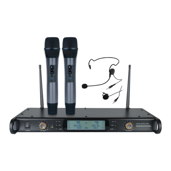
- Page 1 DTM Series Diversity Systems User Manual Order codes: MIC70 - DTM 800H 863.0Mhz-865.0Mhz MIC72 - DTM 600H 606.0Mhz-614.0Mhz MIC70A - DTM 800 863.0Mhz-865.0Mhz MIC72A - DTM 600 606.0Mhz-614.0Mhz...
-
Page 2: Safety Advice
Safety advice Safety advice WARNING FOR YOUR OWN SAFETY, PLEASE READ THIS USER MANUAL CAREFULLY BEFORE YOUR INITIAL START-UP! • Before your initial start-up, please make sure that there is no damage caused during transportation. • Should there be any damage, consult your dealer and do not use the equipment. • To maintain the equipment in good working condition and to ensure safe operation, it is necessary for the user to follow the safety instructions and warning notes written in this manual. • Please note that damages caused by user modifications to this equipment are not subject to warranty. CAUTION! CAUTION! KEEP THIS EQUIPMENT TAKE CARE USING AWAY FROM MOISTURE, THIS EQUIPMENT! RAIN AND LIQUIDS, AND HIGH VOLTAGE-RISK OUT OF DAMP/HUMID... - Page 3 Product overview & technical specifications DTM Series Diversity Systems DTM series wireless microphones feature twin UHF belt pack or handheld systems with 20 (863-865Mhz) or 80 (606-614Mhz) selectable frequencies. Available in either Channel 38 (606-614Mhz) for the DTM600 or Channel 70 (863-865Mhz) for the DTM800; both systems utilise a true diversity, full bandwidth receiver for the ultimate in RF stability. Outstanding vocal reproduction and stable wireless connectivity allow freedom of movement on stage. These systems offer crystal clear sound reproduction and rock solid reliability. Metal bodied transmitters feature ergonomic design with a rugged housing to stand up to the rigours of the road. Supplied with a foam lined carry case for protection during transit. The flexibility of the handheld systems may be increased by purchasing the additional DTM 600BP. • Phase Lock Loop (PLL) • LCD transmitter display • Transmitter battery configuration: 2 x 1.5V AA (not supplied) • IR sync facility for simple setup • Auto frequency scanning • Audio output level: 400mV • True diversity receiver • Balanced XLR output for each channel plus unbalanced • Dynamic range: 96dB • 863-865Mhz - 20 frequencies mixed output or 606-614Mhz - 80 frequencies • Receiver power supply: 9V DC • Frequency response (handheld): (mains adaptor supplied) • Large LCD receiver display 40Hz-15kHz including RF level, AF level, • 1U full width rack mount receiver channel and frequency Specifications DTM 800H Twin Handheld DTM 600H Twin Handheld DTM 800 Twin Beltpack DTM 600 Twin Beltpack...
-
Page 4: Operating Instructions
Operating instructions Receiver front panel identification: 1. Power Switch 8. Down Button – Channel B 13. Balanced Audio Output B On/Off control for the system receiver 9. Set Button – Channel B Individual, balanced audio outputs via 3 pin XLR for audio channel B. 2. Volume Control – Channel A 10. Up Button – Channel B 14. Balanced Audio Output A The receivers output volume is 11. Volume Control – Channel B adjustable. Turn the level control anti Individual, balanced audio outputs The receiver’s output volume is clockwise to the lowest setting, or via 3 pin XLR for audio channel A. adjustable. Turn the level control anti turn clockwise to adjust to the highest clockwise to the lowest setting, or 15. Audio (MIX) Output setting. Each channel features an turn clockwise to adjust to the highest 6.35mm (1/4”) jack socket outputting independent volume control. setting. Each channel features an an unbalanced, line level audio output 3. IR Transceiver independent volume control. featuring both audio channels. The IR transceiver is used to 16. DC Power Input communicate with the systems Receiver rear panel The receiver is powered by a standard transmitters during setup. -
Page 5: Display Identification
Operating instructions Display Identification: 1. RF Level The RF level indicator is a visual representation of the radio frequency signal strength utilising a 10 segment bar graph. As the radio signal received is reduced, the bar graph will reduce. 2. AF Level The AF level indicator is a visual representation of the audio signal strength utilising a 10 segment bar graph. As the audio signal fluctuates bar graph will indicate this. 3. Channel indicator Displays the current RF channel in use by the transmitter/receiver. 4. Frequency Displays the current RF frequency in use by the transmitter/receiver. 5. Battery Level The receiver displays the current battery level in the transmitters allowing remote monitoring of the transmitters battery level. 6. IR Sync During synchronisation, the IR Sync will flash a radiating symbol. 7. Lock The receiver features a lock function to prevent accidental changes to the settings. Press and hold LOCK to unlock the menu system. After a short period of inactivity, the display will automatically lock. 8. Hi/Lo transmit power The user may select the RF transmission power from the menu system. When used in close proximity, the transmitters should be set to Lo or over greater distances, set to Hi. Operation: • Carefully, lift the antennae into the vertical position. • Connect the included power supply to a suitable 240V AC~50Hz mains voltage outlet and plug the DC connector into the DC. Power Input on the rear panel of the receiver (9V DC, 1500mA minimum). • Using the supplied audio cable, connect the MIX OUT on the rear panel of the receiver for both audio channels to the mixer’s audio line input. The receiver also features balanced XLR outputs, one for each channel. • Switch on the power to the receiver, checking the display backlight illuminates. • Open the battery compartment on the transmitter (Beltpack – slide downwards away from the belt clip. Handheld - unscrew the lower portion). Install the appropriate batteries into the transmitter, taking care to observe the orientation and polarity. Only use high quality, alkaline type batteries. Refit the battery compartment cover carefully. • Switch on the transmitter, when switched on the display on the transmitter will illuminate. -
Page 6: Handheld Transmitter
Operating instructions Operation continued: Handheld transmitter • identification: Frequency Scan Mode: To allow the user to select a frequency free from interference, the receiver 1. Grille features a frequency scan mode. Firstly, switch on any transmitters from other 2. LCD Display systems in the vicinity. Press and hold the SET button to unlock the menu 3. IR Transceiver function and then press SET until the display shows a rectangle underneath 4. Power Switch the frequency header. Use the Up or Down keys to commence scanning. The receiver will stop scanning when it reaches the first available frequency. Further 5. Battery compartment scanning can be triggered by pressing the up/down button again. After chang- ing the frequency, the IR sync must be carried out to ensure the transmitter is matched for correct operation. flashes changes • Transmitter Power Mode: The user may select the RF transmission power from the menu system. When used in close proximity, the transmitters should be set to Lo or over greater distances, set to Hi. Press and hold the SET button to unlock the menu function, then press the SET button twice more until the POW selection flashes. Press the SET button to confirm selection. After changing the power setting, the IR sync must be carried out to ensure the transmitter is matched for correct operation. When the POW is flashing, the HI can be adjusted to LO • IR Sync Operation: After making changes to the settings on the receiver, the IR Sync operation should be carried out to ensure the settings are replicated into the transmitter to ensure correct operation. Power on both the transmitter and receiver, cycle thru the menu system on the receiver until all settings are correct. Press and hold the SET button to trigger the IR Sync operation. The IR Sync indicator will show the radiating symbol,... -
Page 7: Troubleshooting
Operating instructions & troubleshooting Beltpack transmitter identification: 1. Microphone Input 2. Volume Control 3. On / Off Switch 4. Power Indictor (illuminates when battery is low and requires changing) 5. Antenna 6. LCD Display 7. IR Transceiver 8. Battery compartment (care should be taken to observe battery polarity) 9. Battery cover Troubleshooting: Problem Possible cause Solution Receiver – no sound Power button is in the OFF position. DC power adapter Turn on the power button plug in the power adapter is not plugged in Receiver – no LED Mic transmitter is out of range. Mic is switched off. Mic Ensure that the mic is within range. Turn on the mic switch. Microphone - no sound volume it turned down. Batteries in mic are not installed Turn up the mic volume on the receiver. Reinstall or use new but LED indicators are lit properly. Receiver is not connected to an amp or mixer. batteries. Connect an output cable to an amp or mixer The 4 mics may be too close together. Batteries are running Increase the distance between mics. Replace the batteries. Distorted sound or feedback out of charge. Mic volume may be too high. Possible Reduce the volume. Move the system away from other interference from another source. -
Page 8: Weee Notice
WEEE notice Correct Disposal of this Product (Waste Electrical & Electronic Equipment) (Applicable in the European Union and other European countries with separate collection systems) This marking shown on the product or its literature, indicates that it should not be disposed of with other household wastes at the end of its working life. To prevent possible harm to the environment or human health from uncontrolled waste disposal, please separate this from other types of wastes and recycle it responsibly to promote the sustainable reuse of material resources. Household users should contact either the retailer where they purchased this product, or their local government office, for details of where and how they can take this item for environmentally safe recycling. Business users should contact their supplier and check the terms and conditions of the purchase contract. This product should not be mixed with other commercial wastes for disposal. www.prolight.co.uk DTM Series User Manual...
Need help?
Do you have a question about the MIC70-DTM 800H and is the answer not in the manual?
Questions and answers