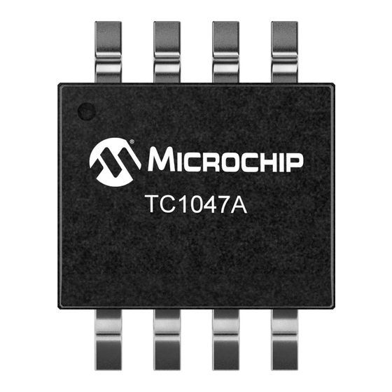
Summary of Contents for Microchip Technology TC1047A
- Page 1 TC1047A Temperature-to-Voltage Converter PICtail™ Demo Board User’s Guide © 2006 Microchip Technology Inc. DS51483B...
- Page 2 Mode, Smart Serial, SmartTel, Total Endurance, UNI/O, WiperLock and ZENA are trademarks of Microchip Technology Incorporated in the U.S.A. and other countries. SQTP is a service mark of Microchip Technology Incorporated in the U.S.A. All other trademarks mentioned herein are property of their respective companies.
-
Page 3: Table Of Contents
Table of Contents Preface ........................... 1 Chapter 1. Product Overview 1.1 Introduction ..................... 5 1.2 What is the TC1047A Temperature-to-Voltage Converter PICtail™ Demo Board? ......................5 1.3 What the TC1047A Temperature-to-Voltage Converter PICtail™ Demo Board Kit includes ................... 5 Chapter 2. Installation and Operation 2.1 Introduction ..................... - Page 4 TC1047A Temperature-to-Voltage Converter PICtail™ Demo Board User’s Guide NOTES: © 2006 Microchip Technology Inc. DS51483B-page iv...
-
Page 5: Preface
This document describes how to use the TC1047A Temperature-to-Voltage Converter PICtail™ Demo Board as a development tool. The manual layout is as follows: • Chapter 1. “Product Overview” – Important information about the TC1047A Temperature-to-Voltage Converter PICtail™ Demo Board. • Chapter 2. “Installation and Operation” – This chapter includes instructions on how to get started, with a detailed description of each of the board’s functions. - Page 6 (void) user { ... RECOMMENDED READING This user's guide describes how to use TC1047A Temperature-to-Voltage Converter PICtail™ Demo Board. The following Microchip documents are available and recommended as supplemental reference resources. TC1047A Data Sheet, “Precision Temperature-to-Voltage Converter” (DS21498) This data sheet provides detailed information regarding the TC1047A device.
-
Page 7: Customer Support
Technical support is available through the web site at: http://support.microchip.com DOCUMENT REVISION HISTORY Revision B (July 2006) • Add disclaimer to Bill of Materials regarding RoHS-Compliant part numbers. Revision A (June 2004) • Initial Release of this Document. © 2006 Microchip Technology Inc. DS51483B-page 3... - Page 8 TC1047A Temperature-to-Voltage Converter PICtail™ Demo Board User’s Guide NOTES: © 2006 Microchip Technology Inc. DS51483B-page 4...
-
Page 9: Chapter 1. Product Overview
Flash Starter Kit as a platform. A PIC16F676 14-pin Flash-based 8-bit CMOS microcontoller device is included with the Demo Board that can be used with PICkit 1 Flash Starter Kit, along with firmware that provides the interface to the TC1047A and the voltage-to-temperature conversion routines. - Page 10 TC1047A Temperature-to-Voltage Converter PICtail™ Demo Board User’s Guide NOTES: © 2006 Microchip Technology Inc. DS51483B-page 6...
-
Page 11: Chapter 2. Installation And Operation
Chapter 2. Installation and Operation INTRODUCTION The TC1047A Temperature-to-Voltage Converter PICtail™ Demo Board demonstrates how to interface the TC1047A device to a microcontroller for use by the system designer as an example of how to integrate an analog temperature sensor into their system. - Page 12 1. Connect the P1 header of the TC1047A Temperature-to-Voltage Converter PICtail™ Demo Board to the J3 connector on the PICkit 1 Flash Starter Kit board. Refer to Figure 2-2 for proper orientation of the TC1047A Temperature-to-Voltage Converter PICtail™ Demo Board and Figure 2-3 for the simplified board schematic.
- Page 13 Programming the PIC16F676 1. Download and install the PICkit 1 Flash Starter Kit software to your PC. 2. Copy the TC1047A PICtail.HEX file, supplied on the CD that came with this kit, to your PC. 3. When the PICkit 1 Flash Starter Kit is started, the main window will be displayed on the PC, as indicated in Figure 2-4.
- Page 14 TC1047A Temperature-to-Voltage Converter PICtail™ Demo Board User’s Guide At this point, the PIC16F676 device is reading the temperature data from the TC1047A and displaying the temperature on the eight red LEDs (D7-D0) on the PICkit 1 Flash Starter Kit board. The ten’s digit of the temperature data is represented by bits D7-D4, with D7 being defined as the Most Significant bit (MSb).
- Page 15 PICkit™ 1 Flash Starter Kit LED Display of 75°F. The temperature display will change when the temperature of the TC1047A is varied. A simple example of this can be seen by pressing your finger on the TC1047A device (U1) on the TC1047A Temperature-to-Voltage Converter PICtail™ Demo Board. More dramatic changes can be seen by applying heat to the TC1047A with a hair dryer or hot air gun, or by cooling the device down.
- Page 16 TC1047A Temperature-to-Voltage Converter PICtail™ Demo Board User’s Guide NOTES: © 2006 Microchip Technology Inc. DS51483B-page 12...
-
Page 17: Appendix A. Schematic And Layouts
CONVERTER PICtail™ DEMO BOARD USER’S GUIDE Appendix A. Schematic and Layouts INTRODUCTION This appendix contains the following schematics and layouts for the TC1047A Temper- ature-to-Voltage Converter PICtail™ Demo Board User’s Guide: • Board Schematic • Board - Top Layer • Board - Silk Screen Layer •... -
Page 18: Board Schematic
TC1047A Temperature-to-Voltage Converter PICtail™ Demo Board User’s Guide BOARD SCHEMATIC PICkit™ 1 Flash Starter Kit Expansion Header J3 BOARD - TOP LAYER © 2006 Microchip Technology Inc. DS51483B-page 14... -
Page 19: Board - Silk Screen Layer
Schematic and Layouts BOARD - SILK SCREEN LAYER BOARD - BOTTOM LAYER © 2006 Microchip Technology Inc. DS51483B-page 15... - Page 20 TC1047A Temperature-to-Voltage Converter PICtail™ Demo Board User’s Guide NOTES: © 2006 Microchip Technology Inc. DS51483B-page 16...
-
Page 21: Appendix B. Bill Of Materials (Bom)
® ® Conn Hdr Brkway .100 40pos RT/A /Tyco 4-103765-0 Electronics TC1047A Precision Temperature To Voltage Microchip TC1047AVNB Converter Technology Inc. Note 1: The components listed in this Bill of Materials are representative of the PCB assembly. The released BOM used in manufacturing uses all RoHS-compliant components. -
Page 22: Worldwide Sales And Service
Fax: 765-864-8387 Tel: 66-2-694-1351 Los Angeles Fax: 66-2-694-1350 Mission Viejo, CA Tel: 949-462-9523 Fax: 949-462-9608 San Jose Mountain View, CA Tel: 650-215-1444 Fax: 650-961-0286 Toronto Mississauga, Ontario, Canada Tel: 905-673-0699 Fax: 905-673-6509 06/08/06 © 2006 Microchip Technology Inc. DS51483B-page 18...


Need help?
Do you have a question about the TC1047A and is the answer not in the manual?
Questions and answers