Table of Contents
Advertisement
Quick Links
Download this manual
See also:
User Manual
Advertisement
Table of Contents

Summary of Contents for Microchip Technology MCP1640
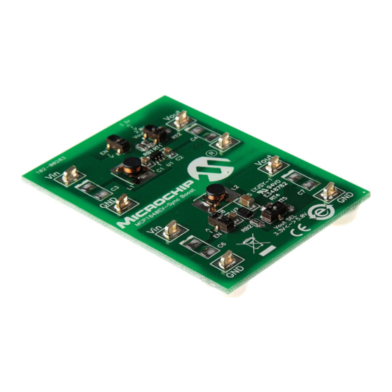
- Page 1 MCP1640 Synchronous Boost Converter Evaluation Board User’s Guide 2010 Microchip Technology Inc. DS51880A...
- Page 2 TSHARC, UniWinDriver, WiperLock and ZENA are trademarks of Microchip Technology Incorporated in the U.S.A. and other countries. SQTP is a service mark of Microchip Technology Incorporated in the U.S.A. All other trademarks mentioned herein are property of their respective companies.
-
Page 3: Table Of Contents
Document Revision History ................... 8 Chapter 1. Product Overview 1.1 Introduction ..................... 9 1.2 What is the MCP1640 Synchronous Boost Converter Evaluation Board? ..9 1.3 What the MCP1640 Synchronous Boost Converter Evaluation Board Includes ....................10 Chapter 2. Installation and Operation 2.1 Introduction .................... - Page 4 MCP1640 Synchronous Boost Converter Evaluation Board User’s Guide NOTES: 2010 Microchip Technology Inc. DS51880A-page 4...
-
Page 5: Preface
• Document Revision History DOCUMENT LAYOUT This document describes how to use the MCP1640 Synchronous Boost Converter Evaluation Board as a development tool. The manual layout is as follows: • Chapter 1. “Product Overview” – Important information about the MCP1640 Synchronous Boost Converter Evaluation Board. -
Page 6: Conventions Used In This Guide
MCP1640 Synchronous Boost Converter Evaluation Board User’s Guide CONVENTIONS USED IN THIS GUIDE This manual uses the following documentation conventions: DOCUMENTATION CONVENTIONS Description Represents Examples Arial font: ® Italic characters Referenced books MPLAB IDE User’s Guide Emphasized text ...is the only compiler... -
Page 7: Recommended Reading
This data sheet provides detailed information regarding the MCP1640 device. • AN1311, Single Cell Input Boost Converter Design (DS01311) This application note details how to use the MCP1640 device in specific applications. THE MICROCHIP WEB SITE Microchip provides online support via our web site at www.microchip.com. This web site is used as a means to make files and information easily available to customers. -
Page 8: Document Revision History
MCP1640 Synchronous Boost Converter Evaluation Board User’s Guide DOCUMENT REVISION HISTORY Revision A (February 2010) • Initial Release of this Document. 2010 Microchip Technology Inc. DS51880A-page 8... -
Page 9: Chapter 1. Product Overview
(20 µA), a wide input voltage range (0.35 to 5.5V) and low start-up voltage (0.65V). The MCP1640 is available in SOT-23-6 and 2x3mm-8 DFN packages. This chapter provides an overview of the MCP1640 Boost Controller Evaluation Board and covers the following topics: •... -
Page 10: What The Mcp1640 Synchronous Boost Converter Evaluation Board Includes
MCP1640 Synchronous Boost Converter Evaluation Board User’s Guide An enable (EN Switch selection) is used to enable and disable the MCP1640. When enabled, the MCP1640 will regulate the output voltage; when disabled, the MCP1640 disconnects the path from input to output for “true-disconnect”. -
Page 11: Chapter 2. Installation And Operation
Li-Polymer batteries in addition to distributed 3.3V to 5.0V applications. The MCP1640 is capable of regulating the output voltage over a wide 2.0V to 5.5V range and typically can deliver over 100 mA of load current at 3.3V output when supplied from a single 1.2V cell. -
Page 12: Features
(3.3V and 5.0V) also selectable by an on board mini-dip switch. Soldered test points are available to connect a load. The MCP1640 switch peak current limit will provide a safe maximum current value. The maximum output current for the MCP1640 will vary with input and output voltages;... -
Page 13: Installation And Operation
2. Set the desired output voltage using the V SEL mini dip switch. 3. Set the enable to the desired state using the EN mini dip switch. 4. When EN is set ON or high, the MCP1640 is enabled and V can be measured on the V and GND terminals. - Page 14 MCP1640 Synchronous Boost Converter Evaluation Board User’s Guide 2.3.1.4 ADJUSTABLE V SETTING The resistor divider RT and RB are used to set the converter output voltage. By setting the V SEL switch in the open or OFF position, the output voltage can be calculated using the following equation: ...
-
Page 15: Appendix A. Schematic And Layouts
CONVERTER EVALUATION BOARD USER’S GUIDE Appendix A. Schematic and Layouts INTRODUCTION This appendix contains the following schematics and layouts for the MCP1640 Synchronous Boost Converter Evaluation Board: • Board – Schematic • Board – Top Silk and Pads • Board – Top Copper Layer •... -
Page 16: Board - Schematic
MCP1640 Synchronous Boost Converter Evaluation Board User’s Guide BOARD – SCHEMATIC 2010 Microchip Technology Inc. DS51880A-page 16... -
Page 17: Board - Top Silk And Pads
Schematic and Layouts BOARD – TOP SILK AND PADS 2010 Microchip Technology Inc. DS51880A-page 17... -
Page 18: Board - Top Copper Layer
MCP1640 Synchronous Boost Converter Evaluation Board User’s Guide BOARD – TOP COPPER LAYER 2010 Microchip Technology Inc. DS51880A-page 18... -
Page 19: Board - Bottom Copper Layer
Schematic and Layouts BOARD – BOTTOM COPPER LAYER 2010 Microchip Technology Inc. DS51880A-page 19... - Page 20 MCP1640 Synchronous Boost Converter Evaluation Board User’s Guide NOTES: 2010 Microchip Technology Inc. DS51880A-page 20...
-
Page 21: Appendix B. Bill Of Materials (Bom)
INDUCTOR POWER 4.7UH 2.0A EPCOS Inc B82462G4472M RoHS Compliant Bare PCB, Microchip Technology 104-00283 MCP1640 Sync Boost Converter Inc. Evaluation Board RB1, RB2 RES 309K OHM 1/8W 1% 0805 SMD Rohm Semiconductor MCR10EZPF3093 RES 536K OHM 1/8W 1% 0805 SMD Yageo... -
Page 22: Worldwide Sales And Service
Tel: 66-2-694-1351 Tel: 408-961-6444 Fax: 86-29-8833-7256 Fax: 66-2-694-1350 Fax: 408-961-6445 China - Xiamen Toronto Tel: 86-592-2388138 Mississauga, Ontario, Fax: 86-592-2388130 Canada Tel: 905-673-0699 China - Zhuhai Fax: 905-673-6509 Tel: 86-756-3210040 Fax: 86-756-3210049 01/05/10 2010 Microchip Technology Inc. DS51880A-page 22...


Need help?
Do you have a question about the MCP1640 and is the answer not in the manual?
Questions and answers