Table of Contents
Advertisement
Quick Links
SAFETY PRECAUTION FOR SERVICE MANUAL ........................................................................................................... 2
VOLTAGE SELECTION ..................................................................................................................................................... 2
AC POWER CORD AND PLUG ADAPTOR ...................................................................................................................... 2
SPECIFICATIONS ............................................................................................................................................................. 3
NAMES OF PARTS ........................................................................................................................................................... 3
DISASSEMBLY .................................................................................................................................................................. 5
REMOVING AND REINSTALLING THE MAIN PARTS ..................................................................................................... 7
ADJUSTMENT ................................................................................................................................................................... 9
TEST MODE .................................................................................................................................................................... 10
NOTES ON SCHEMATIC DIAGRAM .............................................................................................................................. 12
TYPES OF TRANSISTOR AND LED ............................................................................................................................... 12
VOLTAGE ........................................................................................................................................................................ 13
BLOCK DIAGRAM ........................................................................................................................................................... 14
SCHEMATIC DIAGRAM / WIRING SIDE OF P.W.BOARD ............................................................................................. 18
FUNCTION TABLE OF IC ................................................................................................................................................ 36
FL DISPLAY ..................................................................................................................................................................... 40
REPLACEMENT PARTS LIST/EXPLODED VIEW
SERVICE MANUAL
CONTENTS
SHARP CORPORATION
MINI COMPONENT SYSTEM
CD-XP160W
MODEL
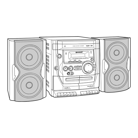
CD-XP160W Mini Component System consisting of CD-
XP160W (main unit) and CP-XP160 (speaker system).
• In the interests of user-safety the set should be restored to its
original condition and only parts identical to those specified be
used.
This document has been published to be used
for after sales service only.
The contents are subject to change without notice.
CD-XP160W
No. S3321CDXP160W
Page
Advertisement
Table of Contents

Related Manuals for Sharp CD-XP160W


Summary of Contents for Sharp CD-XP160W
-
Page 1: Table Of Contents
MINI COMPONENT SYSTEM CD-XP160W MODEL CD-XP160W Mini Component System consisting of CD- XP160W (main unit) and CP-XP160 (speaker system). • In the interests of user-safety the set should be restored to its original condition and only parts identical to those specified be used. -
Page 2: Safety Precaution For Service Manual
CD-XP160W SAFETY PRECAUTION FOR SERVICE MANUAL Precaution to be taken when replacing and servicing the Laser Pickup. The AEL (Accessible Emission Level) of Laser Power Output Laser Diode Properties for this model is specified to be lower than Class 1 Material: GaAIAs Requirements. -
Page 3: Specifications
CD-XP160W FOR A COMPLETE DESCRIPTION OF THE OPERATION OF THIS UNIT, PLEASE REFER TO THE OPERATION MANUAL. SPECIFICATIONS General Tuner Frequency range FM: 88 - 108 MHz Power source AC 110/127/220/230 - 240 V, 50/60 Hz AM: 531 - 1,602 kHz... -
Page 4: Rear Panel
CD-XP160W Display 1. CD Play Indicator 2. CD Repeat Play Indicator 3. FM Station Indicator 4. AM Station Indicator 5. Disc Number Indicators 6. Clock Indicator 7. Sleep Indicator 8. Timer Play Indicator 9. Tape 1 Record Indicator 10. CD Pause Indicator 11. -
Page 5: Disassembly
CD-XP160W DISASSEMBLY Top Cabinet Caution on Disassembly Follow the below-mentioned notes when disassembling Front (A1)x2 Panel the unit and reassembling it, to keep it safe and ensure ø3x16mm excellent performance: Side Panel 1. Take cassette tape and compact disc out of the unit. - Page 6 CD-XP160W (P1)x3 (P2)x1 (P2)x1 Front Panel Display PWB ø3x24mm (G2)x1 Display PWB (Q1)x2 ø3x8mm (H1)x10 ø2.5x10mm Loading Power Switch Tray Tape CD Servo Mechanism (J1)x8 ø3x10mm Open (G1)x3 (P2)x2 ø2.5x10mm Cassette Loading Switch Holder (P2)x1 (L1)x2 (K1)x1 ø2.5x10mm ø2.5x10mm Figure 6-3...
-
Page 7: Removing And Reinstalling The Main Parts
CD-XP160W REMOVING AND REINSTALLING THE MAIN PARTS (A1)x1 TAPE MECHANISM SECTION TAPE 1 ø2x7mm (A1)x1 Perform steps 1 to 6 and 9 of the disassembly method to ø2x3mm Hook remove the tape mechanism. (A2)x2 Record/Playback How to remove the record/playback and erase Head heads (TAPE 1) (See Fig. -
Page 8: Cd Mechanism Section
CD-XP160W CD MECHANISM SECTION Perform steps 1, 2, 3, 12, 13, 14 and 16 of the disassembly (B1)x4 method to remove the CD mechanism. ø3x8mm (B1)x2 ø3x8mm Loading How to remove the T/T up/down motor (A1)x4 Tray ø3x8mm (See Figs. 8-1, 8-2) 1. -
Page 9: Adjustment
CD-XP160W ADJUSTMENT MECHANISM SECTION TUNER SECTION • • • • • Driving Force Check fL: Low-range frequency fH: High-range frequency Torque Meter Specified Value • • • • • AM IF/RF Play: TW-2111 Tape 1: Over 80 g Signal generator: 400 Hz, 30%, AM modulated... -
Page 10: Test Mode
CD-XP160W TEST MODE PLAY + DISC SKIP test04 TIMER ON/OFF TEST MODE FL DISPLAY: STOP + DISC SKIP test05 VFD DISPLAY WINDOW TEST MODE FL DISPLAY: VFD ALL LIGHT FUNCTION: TEST THE VFD DISPLAY WINDOW PLAY + OPEN/CLOSE test08 OPEN/CLOSE & 3 DISC CHANGER AGING TEST... - Page 11 CD-XP160W PLAY + VOLUME DOWN test06 FRONT PANEL KEY TEST FL DISPLAY: FUNCTION: FRONT PANEL KEY TEST MODE,IF ALL KEY HAVE BEEN PRESSED 1 TIME, THEN PRESS THE "POWER" KEY, VFD DISPLAY "OK". PLAY + VOLUME UP test03 VOLUME TEST MODE...
-
Page 12: Notes On Schematic Diagram
CD-XP160W NOTES ON SCHEMATIC DIAGRAM • Resistor: • The indicated voltage in each section is the one measured by Digital Multimeter between such a section and the chas- To differentiate the units of resistors, such symbol as K and M are used: the symbol K means 1000 ohm and the symbol sis with no signal given. -
Page 13: Voltage
CD-XP160W VOLTAGE IC101 IC401 IC403 IC404 IC701 IC801 Q302 Q408 VOLTAGE VOLTAGE VOLTAGE VOLTAGE VOLTAGE VOLTAGE VOLTAGE VOLTAGE VOLTAGE 18.8 V 2.6 V 0.2 V 4.8 V 2.7 V 0.6 V 2.6 V 2.7 V 2.7 V 1.5 V 0.9 V 0.3 V... -
Page 14: Block Diagram
CD-XP160W TO DIS OPEN CNS701 CLOSE DISC Q402,403 LOAD– T/T UP/DOWN Q405~408 LOAD+ MOTOR MOTOR M_GND DRIVER Q409 ROTATE CD LOADING Q410 MOTOR CONSTANT VOLTAGE Q404 +6.2V M_GND PICKUP IN NM802 SPINDLE MOTOR M_GND NM801 SLED MOTOR 1 2 3 4 5 6... - Page 15 CD-XP160W TO DISPLAY SECTION TO MAIN SECTION CNP701 CNP101 CNS701 CNS101 Q411 RESET Q412 Q413 D_GND CD+B 36 35 34 33 32 31 30 29 28 27 26 FM_ST FM_ST TO MAIN SECTION CNP105 UP_SW DISC_SW IC403 LOAD_SW IX0052SJ PICK_IN...
- Page 16 CD-XP160W ANTENNA FM IF FM IF TA302 FROM CD AM LOOP DZ5.1BSJ T304 CF303 Q306 SECTION ANTENNA CNS105 B.P.F IC301 TA7358AP BF301 CF351 X351 FM FRONT END IC303 456 kHz LA1832S T351 CF352 FM IF DET./ AM IF FM MPX./AM IF...
- Page 17 CD-XP160W VFD701 FL DISPLAY FROM CD SECTION CNS105 CNP105 28 29 SW702~SW715 IC701 SC16312 SYSTEM MICROCOMPUTER REMOTE KEY3 SENSOR KEY1 RX701 CNP701 INTR DATA FROM CD SECTION Q701 JK901 CNS701 LED701 IC902 D_GND NJM4558D POW_SW SW701 SO102 OPE. AMP. POWER...
-
Page 18: Schematic Diagram / Wiring Side Of P.w.board
CD-XP160W AM TRACKING FM SIGNAL FM MUTE T302 LEVEL AM SIGNAL 10K(B) VR351 L353 1µH C329 0.022 D301 1N4148 AM OSC. C335 560P D302 1N4148 T306 AM BAND COVERAGE fL 2.1V CF302 IC301 FM IF FM FRONT END TA7358AP BAND PASS... - Page 19 CD-XP160W MAIN PWB-A1 (1/3) FM MUTE LEVEL TP302 10K(B) Q351 VR351 KRC104 M L353 4.7V 1µH (0V) C371 R361 1/50 5.6K R362 5.6K C372 1/50 2.3V R366 2.2K IC303 LA1832S FM IF DET./ 2.1V FM MPX./AM IF C358 2.1V 1/50...
- Page 20 CD-XP160W MAIN PWB-A1 (2/3) PLAYBACK SIGNAL RECORD SIGNAL TAPE MECHANISM ASS'Y (223) SW5(223-6) PLAY TAPE1 SW6(223-7) FF/REW SW7(223-7) FF/REW CNP803 TAPE2 SW8(223-6) PLAY M2(223-8) TAPE MOTOR – CNP804 TAPE2 TAPE MOTOR PLAYBACK HEAD C812 R801 (223-3) 0.0027 PWB-E(223-9) T1_R R-CH...
- Page 21 CD-XP160W CHANEL_SW TAPE L TAPE R REC R REC L TO MAIN PWB (3/3) R837 R834 +10V MAIN SECTION M_GND P23 7 - B A_GND TAPE_DET MOTOR R835 D803 1N4148 R838 5.6K C840 220/16 C812 R801 0.0027 R808 R802 C815 0.033...
- Page 22 CD-XP160W FROM CD SERVO PWB FROM CD SERVO PWB FROM CD SERVO PWB SW102 TO MAIN PW P25 12 - B P25 9 - A P25 12 - E SPAN SELECTOR TAPE SEC P21 11 CNS105 CNS101 FM/AM (kHz) CNS103...
- Page 23 CD-XP160W C902 R902 R901 C910 470P 0.22/16 2.7K JK901 R907 R913 C912 R911 JACK 1/16 R905 C901 R903 R915 0.0015 R904 L CH 5 6 7 8 C905 CNS107 R909 470P 4.7K C903 IC901 CHASSIS 100/16 R CH C906 IC902 4.7/16...
- Page 24 CD-XP160W CD SERVO PWB-A2 LOADING SWITCH PWB-D CD SIGNAL OPEN LOAD+ CLOSE LOAD– CNS401 CNW401 M_GND ROTATE LOAD SW DISC_SW DISC R418 R421 UP_SW R434 R437 1.5K 1.5K 3.3K Q409 KSC1815 GR Q402 KSC3203 Y C460 UP-DOWN MOTOR PWB-A6 R419 0.022...
- Page 25 CD-XP160W TO DISPLAY PWB TO MAIN PWB(3/3) CNP701 CNP101 P27 11 - F P22 3 - B CNS101 CNS701 CNW701 CNW101 D401 D405 L404 1N4148 1N4148 2.2µH CHANEL_SW R482 L405 D404 R471A Q412 2.2µH 1N4148 R435C KSC1815 GR C426 3.3K R471B 3.3/50...
- Page 26 CD-XP160W EQUALISER DISC SKIP X-BASS/DEMO SW712 SW708 TUNER TAPE (BAND) OPEN/CLOSE SW702 SW705 SW709 SW713 STOP TUNING UP TUNING DOWN PLAY/REPEAT SW703 SW706 SW710 SW714 PRESET UP PRESET DOWN VOLUME UP VOLUME DOWN SW704 SW707 SW711 SW715 VFD701 FL DISPLAY...
- Page 27 CD-XP160W DISPLAY PWB-B SKIP CLOSE REPEAT ME DOWN RX701 GP1UM271 POWER REMOTE SENSOR SWITCH PWB-A4 SW701 POWER ON/STAND-BY C701 100/10 C702 0.047 CNW702 R702 R703 CNP702 CNS702 R704 C703 R713 100P R705 22 21 20 19 18 17 16 15 14 13...
- Page 28 CD-XP160W MAIN PWB-A1 CNW110 C384 TP301 R374 R381 R373 X352 CHASSIS R391 D308 R372 C391 Q360 R365 R392 R371 C142 C380 TA302 C395 R385 R359 R386 C387 C141 ANTENNA R384 R360 C396 R380 R382 TERMINAL R387 C394 L351 75 ohms...
- Page 29 CD-XP160W P30 1 - C P30 1 - D P33 11 - D FROM FROM FROM CD SERVO PWB CD SERVO PWB DISPLAY PWB CNS105 CNS101 CNS102 2 3 4 5 6 7 8 9 10 CNP101 CNP105 C142 R621...
- Page 30 CD-XP160W CNS405 6 5 4 3 2 1 MR401 CORE CNS103 CNW405 R401 CNS105 C450 C447 R485 C448 R456 R486 C437 R446 C458 C460 CNS406 R487 C449 C444 R495 R444 L402 C445 R496 R483 R484 R497 P29 8 - A...
- Page 31 CD-XP160W COLOR TABLE BROWN RD(R) NM801 SLED MOTOR ORANGE CNP405 YELLOW GREEN BLUE VIOLET PICKUP IN GRAY WH(W) WHITE CD MOTOR BLACK PWB-C PINK NM802 SPINDLE MOTOR UP-DOWN CNS406 MOTOR PWB-A6 – R919 T/T UP/DOWN MOTOR CNS407 CNW402A PICKUP UNIT(308)
- Page 32 CD-XP160W DISPLAY PWB-B R712 C703 R701 IC701 RX701 REMOTE SENSOR VFD701 FL DISPLAY 3 4 5 6 7 8 9 10 11 12 13 14 15 16 17 18 19 20 21 22 23 24 25 26 2 D704 SW708...
- Page 33 CD-XP160W COLOR TABLE BROWN R D( R) R713 ORANGE YELLOW R703 R711 GREEN R707 BLUE LED701 VIOLET GRAY W H( W) WHITE BLACK PINK 21 22 23 24 25 26 27 28 29 30 31 32 33 CNS106 D701 D702...
- Page 34 CD-XP160W P28 4 - F TO MAIN PWB CNP104 CNS104 1 2 3 4 5 6 7 POWER PWB-F CNW104 T101 POWER TRANSFORMER 127V 110V 230~240V 220V SO101 SW101 AC INPUT SOCKET VOLTAGE SELECTOR AC 110/127/220 230~240V, 50/60 Hz AC 110/127/220...
- Page 35 CD-XP160W P29 9 - D CNP803 TO MAIN PWB SW5(223-6) SW6(223-7) SW7(223-7) SW8(223-6) TAPE 1 TAPE 1 TAPE 2 TAPE 2 PLAY FF/REW FF/REW PLAY TAPE MOTOR PWB-E M2(223-8) P29 9 - E TAPE MOTOR CNP804 TO MAIN PWB TAPE 1...
-
Page 36: Function Table Of Ic
CD-XP160W FUNCTION TABLE OF IC IC402 VHiAN22000A-1: Head Amp. (AN22000A) Pin No. Terminal Name Function APC amp input. APC amp output. Power supply. RF amp inverting input. RFOUT RF addition amp output. RFIN AGC amp input. CAGC AGC loop filter connection. - Page 37 CD-XP160W IC401 VHiMN6627482W: Servo/Signal Control (MN6627482W) (1/2) Pin No. Terminal Name Input/Output Function BCLK Output SRDATA bit clock output. LRCK Output L/R identification signal output. SRDATA Output Serial data output. DVDD1 Input Digital circuit power supply. DVSS1 Input Digital circuit GND.
- Page 38 CD-XP160W IC401 VHiMN6627482W: Servo/Signal Control (MN6627482W) (2/2) Pin No. Terminal Name Input/Output Function DSLF Input/Output DSL loop filter terminal. PLLF Input/Output PLL loop filter terminal. VCOF Input/Output VCO loop filter terminal. AVDD2 Input Analog circuit power supply. (DSL, PLL and DA output sections for AD)
- Page 39 CD-XP160W IC401 VHiMN6627482W: Servo/Signal Control (MN6627482W) SUBCODE DSL • PLL VCO TIMING DIGITAL BUFFER DEEMPHSIS GENERATOR /RST /TEST PITCH CONTROL DEMODULATION 8TIMES CD-TEXT OVER BUFFER SYNC INTERPOLATION SAMPLING MICRO DIGITAL FILTER SUBCODE DEMODULATION COMPUTER RFENV INTERFACE CIRC ERROR CORRECTION 1 BIT DAC...
-
Page 40: Fl Display
CD-XP160W FL DISPLAY VFD701 VVK250808//-1 M H z k H z M E M O R Y R A N D O M SLEEP X-BASS 2G-7G PIN NO. 9 1 0 1 1 1 2 1 3 1 4 1 5 1 6 1 7 1 8... -
Page 41: Parts Guide
PARTS GUIDE MINI COMPONENT SYSTEM CD-XP160W MODEL CD-XP160W Mini Component System consisting of CD- XP160W (main unit) and CP-XP160 (speaker system). “HOW TO ORDER REPLACEMENT PARTS” To have your order filled promptly and correctly, please furnish the For U.S.A. only following information. - Page 42 CD-XP160W PRICE PRICE DESCRIPTION PARTS CODE DESCRIPTION PART CODE RANK RANK INTEGRATED CIRCUITS ZD351 VHEDZH05C2+-1 AB Zener,5.1V,DZH05C2+ ZD401 VHEDZH03C3+-1 AB Zener,3.3V,DZH03C3+ IC101 VHIAN78L05/-1 AE Voltage Regulator,AN78L05 FILTERS IC102 VHIKIA7810API AE Voltage Regulator,KIA7810API IC103 VHIKIA7808API AF Voltage Regulator,KIA7808API IC201 VHILM4765T+-1 AW Power Amp.,LM4765T+...
- Page 43 CD-XP160W PRICE PRICE DESCRIPTION PART CODE PARTS CODE DESCRIPTION RANK RANK AA 0.001 µF,50V AA 0.012 µF,25V C309 VCKYCY1HB102K C429 VCKYCY1EF123Z AA 0.1 µF,25V C311 VCCCCY1HH100J AA 10 pF (CH),50V C430 VCKYCY1EF104Z AA 0.001 µF,50V C312 VCCSCY1HL330J AD 33 pF,50V...
- Page 44 CD-XP160W PRICE PRICE DESCRIPTION PART CODE PARTS CODE DESCRIPTION RANK RANK R103 VRD-ST2CD473J AA 47 kohms,1/6W R405 VRS-CY1JB101J AA 100 ohm,1/16W R104 VRD-ST2CD123J AA 12 kohms,1/6W R406 VRD-ST2EE4R7J AA 4.7 ohms,1/4W R105,106 VRD-ST2CD331J AA 330 ohms,1/6W R407 VRD-ST2CD393J AA 39 kohms,1/6W...
- Page 45 CD-XP160W PRICE PRICE DESCRIPTION PART CODE PARTS CODE DESCRIPTION RANK RANK R495~499 VRD-ST2CD102J AA 1 kohm,1/6W CNW103/CNS103 QCNWN0576SJZZ J AD Connector Ass’y,3/3Pin R601 VRD-ST2CD102J AA 1 kohm,1/6W CNW104/CNS104 QCNWN0438SJZZ J AG Connector Ass’y,8/7Pin R602,603 VRS-CY1JB102J AA 1 kohm,1/16W CNW105A/B/CNS105 QCNWN0440SJZZ J AF Connector Ass’y,7/2/10Pin...
- Page 46 CD-XP160W PRICE PRICE DESCRIPTION PART CODE PARTS CODE DESCRIPTION RANK RANK 1 235 LX-WZ1070AFZZ AA Washer,ø1.5×ø3.8×0.25mm QFSHD0001AWZZ J AB Holder,Fuse XBBSD20P03000 AA Screw,ø2×3mm PCOVS1008SJSA AG Cover,Power PWB XBSSD26P06000 AA Screw,ø2.6×6mm TLABS0042SJZZ AB Label,Laser XHBSD20P05000 AA Screw,ø2×5mm GCOVA1023SJSA AD Cover,LED NM801...
- Page 47 CD-XP160W PRICE PRICE PART CODE DESCRIPTION PARTS CODE DESCRIPTION RANK RANK QANTW0005SJZZ AC FM Antenna QPLGA9004SJZZ Adaptor,AC Plug [For Saudi Arabia Only] RRMCG0062SJSA J AQ Remote Control SPAKA0150SJZZ AG Packing Add.,Left SPAKA0151SJZZ AG Packing Add.,Right SPAKC0284SJZZ Packing Case [Except for Australia/New...
- Page 48 CD-XP160W 308-2 308-1 308-3 702x2 NM802 NM801 PWB-C Figure 7 CD MECHANISM EXPLODED VIEW – 7 –...
- Page 49 CD-XP160W 615x7 607x2 202-1 601x2 608x3 203-1 202-2x2 606x2 612x2 608x2 235x6 611x2 IC201 614x2 203-2 PWB-A1 IC103 610x2 IC102 224x2 Silicon Silicon PWB-A5 Grease Grease 610x2 610x10 617 PWB-A4 606x2 610x3 610x2 PWB-A8 201-1 611x2 PWB-B VFD701 205-4 602x4...
- Page 50 CD-XP160W 616x2 616x2 257x2 MECHANISM PWB-D 614x2 281x4 606x2 280x4 279x2 619x4 617x2 620x3 620x3 606x2 PWB-A6 611x4 PWB-A7 607x2 606x2 611x4 PWB-A2 613x3 Figure 9 CABINET EXPLODED VIEW (2/2) – 9 –...
- Page 51 CD-XP160W — M E M O — – 10 –...
- Page 52 CD-XP160W © COPYRIGHT 2003 BY SHARP CORPORATION ALL RIGHTS RESERVED. No part of this publication may be reproduced, stored in a retrieval system, or transmitted in any form or by any means, electronic, mechanical, photocopying, recording, or otherwise, without prior written permission of the publisher.
Need help?
Do you have a question about the CD-XP160W and is the answer not in the manual?
Questions and answers