Table of Contents
Advertisement
Quick Links
SAFETY PRECAUTION FOR SERVICE MANUAL ........................................................................................................... 2
IMPORTANT SERVICE NOTES (FOR U.K. ONLY) .......................................................................................................... 2
SPECIFICATIONS ............................................................................................................................................................. 3
NAMES OF PARTS ........................................................................................................................................................... 4
DISASSEMBLY .................................................................................................................................................................. 6
REMOVING AND REINSTALLING THE MAIN PARTS ..................................................................................................... 9
ADJUSTMENT ................................................................................................................................................................. 10
NOTES ON SCHEMATIC DIAGRAM .............................................................................................................................. 14
TYPES OF TRANSISTOR AND LED ............................................................................................................................... 14
BLOCK DIAGRAM ........................................................................................................................................................... 15
SCHEMATIC DIAGRAM / WIRING SIDE OF P.W.BOARD ............................................................................................. 18
VOLTAGE ........................................................................................................................................................................ 35
WAVEFORMS OF CD CIRCUIT ...................................................................................................................................... 36
TROUBLESHOOTING ..................................................................................................................................................... 37
FUNCTION TABLE OF IC ................................................................................................................................................ 41
FL DISPLAY ..................................................................................................................................................................... 47
WIRING OF PRIMARILY SUPPLY LEADS (FOR U.K. ONLY) ....................................................................................... 48
REPLACEMENT PARTS LIST/EXPLODED VIEW
SERVICE MANUAL
MODEL
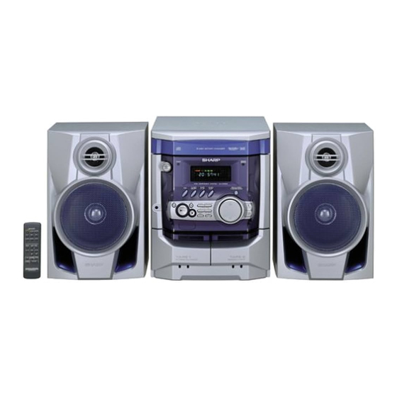
CD-XP200H Mini Component System consisting of CD-XP200H
(main unit) and CP-XP200H (speaker system).
CONTENTS
SHARP CORPORATION
MINI COMPONENT SYSTEM
CD-XP200H
• In the interests of user-safety the set should be restored to its
original condition and only parts identical to those specified be
used.
• Note for users in U.K.
Recording and playback of any material may require consent
which SHARP is unable to give. Please refer particularly to the
provisions of Copyright Act 1956, the Dramatic and Musical
Performers Protection Act 1956, the Performers Protection Acts
1963 and 1972 and to any subsequent statutory enactments and
orders.
This document has been published to be used
for after sales service only.
The contents are subject to change without notice.
CD-XP200H
No. S5236CDXP200H
Page
Advertisement
Table of Contents

Related Manuals for Sharp CD-XP200H


Summary of Contents for Sharp CD-XP200H
-
Page 1: Table Of Contents
• Note for users in U.K. Recording and playback of any material may require consent which SHARP is unable to give. Please refer particularly to the provisions of Copyright Act 1956, the Dramatic and Musical Performers Protection Act 1956, the Performers Protection Acts 1963 and 1972 and to any subsequent statutory enactments and orders. -
Page 2: Safety Precaution For Service Manual
CD-XP200H SAFETY PRECAUTION FOR SERVICE MANUAL Precaution to be taken when replacing and servicing the Laser Diode Properties Laser Pickup. Material: GaAIAs Wavelength: 780 nm Emission Duration: continuous The AEL (Accessible Emission Level) of Laser Power Output Laser Output: max. 0.6 mW for this model is specified to be lower than Class 1 Requirements. -
Page 3: Specifications
CD-XP200H FOR A COMPLETE DESCRIPTION OF THE OPERATION OF THIS UNIT, PLEASE REFER TO THE OPERATION MANUAL. SPECIFICATIONS CD-XP200H (For U.K.) CD-XP200H (Except for U.K.) General General Power source AC 230 V, 50 Hz Power source AC 230 V, 50 Hz... -
Page 4: Names Of Parts
CD-XP200H NAMES OF PARTS CD-XP200H Front panel 1. Disc Tray 2. Timer Set Indicator 3. On/Stand-by Button 4. Tuner (Band) Button 5. CD Button 6. Headphone Socket 7. Tape (1 2) Button 8. Video/Auxiliary Button 9. RDS Programme Type/Traffic Information Search Button 10. - Page 5 CD-XP200H CD-XP200H Remote control 1. Remote Control Transmitter 2. On/Stand-by Button 3. Disc Number Select Buttons 4. CD Random Button 5. CD Memory Button 6. Tape 2 Record Pause Button 7. CD Track Down or Fast Reverse, Tape 2 Rewind Button 8.
-
Page 6: Disassembly
CD-XP200H DISASSEMBLY CD-XP200H Caution on Disassembly Follow the below-mentioned notes when disassembling Top Cabinet the unit and reassembling it, to keep it safe and ensure Front (A1)x2 excellent performance: Panel ø3x12mm 1. Take cassette tape and compact disc out of the unit. - Page 7 CD-XP200H (L1)x3 Loading Tray (E2)x2 (E3)x1 Front Panel (F3)x1 (E2)x1 (E4)x1 (F2)x1 Power PWB Headphones Transformer (L1)x3 Main PWB (F2)x1 (E1)x2 Figure 7-4 ø3x10mm (F1)x2 ø3x10mm (M1)x2 ø3x10mm Figure 7-1 Loading Tray CD Servo (G2)x1 (M3)x2 Front Panel (M2)x1 Display PWB (G1)x12 ø3x10mm...
- Page 8 CD-XP200H CD-XP200H REMOVAL PROCEDURE FIGURE STEP Woofer 1. Front Panel ..... (A1) x1 2. Screw ...... (A2) x4 Tweeter 1. Screw ...... (B1) x2 (A1)x1 Tweeter (B1)x2 ø3x10mm Screwdriver Speaker Box Ass'y Driver should Speaker Box Woofer Ass'y be pried away (A2)x4 from Speaker Box.
-
Page 9: Removing And Reinstalling The Main Parts
CD-XP200H REMOVING AND REINSTALLING THE MAIN PARTS TAPE MECHANISM SECTION TAPE 2 Clutch Ass'y Perform steps 1 to 6 and 8 of the disassembly method to remove the tape mechanism. Record/Playback Head How to remove the record/playback and erase heads (TAPE 2) (See Fig. 9-1) 1. -
Page 10: Adjustment
CD-XP200H CD MECHANISM SECTION Loading Motor PWB Perform steps 1, 2, 3, 10, 11, 12 and 13 of the disassembly Loading method to remove the CD mechanism. Motor Loading How to remove the loading motor Tray (See Fig. 10-1) 1. Bend the hooks (A1) x 5 pcs., to remove the loading motor. - Page 11 CD-XP200H TUNER SECTION CD SECTION fL: Low-range frequency • Adjustment fH: High-range frequency Since this CD system incorporates the following automatic • AM IF/RF adjustment functions, readjustment is not needed when replacing the pickup. Therefore, different PWBs and pickups Signal generator: 400 Hz, 30%, AM modulated can be combined freely.
- Page 12 CD-XP200H TEST MODE • Setting the test mode Any one of test mode can be set by pressing several keys as follows. <X-BASS> + <CD> + <POWER> TEST: CD operation test. Function: -CD test mode. -Enter test mode. T E S T IL isn't done OPEN/CLOSE operation is using manual.
- Page 13 CD-XP200H Standard Specification of Stereo System Error Message Display Contents Error Contents DISPLAY Notes TAPE Mechanism Error. 'ER-TA**' 00: Tape Mechanism Error. 01: Initial Error. Pickup Mechanism Error. 'ER-CD**' 01: PU-IN SW Detection NG. CD Changer Mechanism Error. 'ER-CD**' 10: Changer Error.
-
Page 14: Notes On Schematic Diagram
CD-XP200H NOTES ON SCHEMATIC DIAGRAM • Resistor: • The indicated voltage in each section is the one measured To differentiate the units of resistors, such symbol as K and by Digital Multimeter between such a section and the chas- M are used: the symbol K means 1000 ohm and the symbol sis with no signal given. -
Page 15: Block Diagram
CD-XP200H DISC CLAMP NUMBER OPEN/ CLOSE T/T UP DOWN LOADING TO MAIN SECTION TO DISPLAY SECTION MOTOR – 9 10 CNP8 CNP7 LC78645NE CD SERVO XOUT 17 25 CONT5 SLDO SPDO VCC4 M63001FP VCC1 FOCUS/TRACKING/ VCC2 SPIN/SLED +3.3V DRIVER VCC3 +3.3V... - Page 16 CD-XP200H IC303 LA1832S ZD351 FM IF DET. FE301 5.1V FM IF FM MPX./AM IF FM FRONT END AMP. 10.7 MHz SO301 CF301 CF302 Q301 FM ANTENNA X351 TERMINAL 450 kHz CF351 456 kHz T351 CF352 AM IF 12 20 AM LOOP...
- Page 17 CD-XP200H FL701 FL DISPLAY TO CD SECTION TAPE MECHANISM Q705 ASS'Y +B10 RX701 54 59 52 51 55 40 25 13 30 49 50 REMOTE SENSOR +B10 +B10 IC701 VLOAD AVDD IX0532AW SYSTEM SW701-SW705 SW711-SW729 MICROCOMPUTER (1/2) 1 2 4 5 6 7 8...
-
Page 18: Schematic Diagram / Wiring Side Of P.w.board
CD-XP200H MAIN PWB-A1 (1/3) CD SIGNAL FM SIGNAL VIDEO SIGNAL PLAYBACK SIGNAL C602 RECORD SIGNAL 0.022 R-CH VREF INTERFACE + – Q603, Q604: SYSTEM MUTE C609 R605 A_GND 1/50 LOUT ROUT L-CH C607 R607 CD_GND 3.9K 0.12 LBASS RBASS R613... - Page 19 CD-XP200H L-CH C691 R691 R693 6.8K 390P R601 AUX IN C690 R690 6.8K 390P R602 R-CH R692 R603 JK690 C603 VIDEO/AUX 22/50 VREF R604 C610 1/50 ROUT C608 0.12 RBASS R606 C606 3.9K RTRE 0.12 C612 0.0022 C614 CHASSIS 1/50...
- Page 20 CD-XP200H C302 0.001 L354 CHASSIS LOW PASS FILTER TP302 C342 R365 0.022 R358 3.9K R350 2.7K X351 C367 456 kHz AM TRACKING 1/50 T303 C331 0.047 C323 C330 0.022 (UJ) C332 0.022 AM ANTENNA C358 10 11 D301 AM BAND...
- Page 21 CD-XP200H MAIN PWB-A1 (2/3) FILTER R370 TP302 C373 0.015 C371 1/50 C372 X351 1/50 56 kHz CT23 CT25 CT29 22P(CH) RT24 0.022 XT21 4.332 MHz (CH) RT26 ICT21 C358 10 11 1/50 LC72723 R353 QT21 R355 RT25 KTC3199 GR 3.3K...
- Page 22 CD-XP200H IC901 L-CH R-CH STK4029S POWER AMP. +VCC –VCC C908 820P R925 R942 R938 C907 C913 820P 100/63 C905 R943 3.3P R939 R903 (CH) R921 R945 1.5K R913 100(1/4W) R907 C915 C916 Fusible 0.1 (1W) 10/63 10/63 R914 RL914 R909 0.1 (1W)
- Page 23 CD-XP200H FM SIGNAL C930 47/50 – D912 R949 FAN MOTOR DS1SS133 R947 C931 R950 10/50 R938 R942 R943 R939 CNP705 R945 R944 M_+13.5V 1.5K 1.5K SP_RLY R-CH L702 RL914 2.2 µH L-CH C719 JK701 C718 HEADPHONES 0.001 0.001 HLD803 FW803...
- Page 24 CD-XP200H DISPLAY PWB-B1 FL701 FL DISPLAY R794 9 8 7 6 5 4 3 45 44 43 42 41 40 39 38 37 36 35 34 33 32 30 29 28 27 26 25 24 23 22 21 20 19 18 17 16 15 14 13 12...
- Page 25 CD-XP200H 9 8 7 6 5 4 3 2 1 13 12 11 10 R795 C701 1/50 92 93 94 95 96 97 98 99 R763 R702 T-BIAS –20dBATT R703 T_T1/T2 R704 REC/PLAY R705 CD RESOUT R706 SPAN R708 RESET...
- Page 26 CD-XP200H CD SERVO PWB-C CD SIGNAL 100P 0.022 100P PICKUP UNIT 100P 56P(C 100P PICKUP HPC1LX 0.022 VREF VREF 1.2K 8.2K 8.2K 0.047 80 79 78 77 76 75 74 73 72 71 7 8.2K EFMIN 0.001 RFVDD 0.0027 SLCO...
- Page 27 CD-XP200H 100P(CH) 0.022 100P(CH) 100P(CH) 56P(CH) 100P(CH) 0.022 CD RES CLAMP SW 2.2K DISC NO 2.2K 9 78 77 76 75 74 73 72 71 70 69 68 67 66 65 64 63 62 61 LRCK ASDFIN ASDACK DATA SLCO...
- Page 28 CD-XP200H MAIN PWB-A1 CT29 C302 C348 R373 X352 R372 Q301 RT26 R378 R388 R374 QT21 C382 R359 1 2 3 4 5 6 7 8 9 10 11 ZDT21 B C E CF301 R376 IC302 1 2 3 C387 R360...
- Page 29 CD-XP200H P31 12 - D TO DISPLAY PWB CNP701 FFC701 P32 4 - A TO CD SERVO PWB CNP7 CT22 1 2 3 4 5 6 7 8 CNS601 COLOR TABLE CT30 BROWN C619 R136 C615 Q108 B C E...
- Page 30 CD-XP200H DISPLAY PWB-B1 RX701 C716 5 6 7 8 9 10 11 12 13 14 15 16 17 18 19 R783 FL701 R793 R792 B C E R763 Q705 R702 C703 D714 SW729 D713 PTY.TI R703 SEARCH R704 RD26 Q709...
- Page 31 CD-XP200H R788 LED701 27 28 29 30 31 32 33 34 35 36 37 38 39 40 41 FL701 SW701 ON/STAND-BY R792 RD01 R745 R744 R743 R742 C706 IC701 R732 R731 R730 R762 R729 30 31 R736 R718 R768 C720...
- Page 32 CD-XP200H P30 1 - D P29 9 - B FROM DISPLAY PWB FROM MAIN PWB CNS701 CNS601 CD SERVO PWB-C CNP7 1 2 3 4 5 6 7 8 9 10 1 2 3 4 5 6 7 8 CNP8...
- Page 33 CD-XP200H P30 3 - G TAPE MECHANISM TO DISPLAY PWB ASSEMBLY CNP702 FFC702 TAPE MECHANISM PWB-F SOLENOID SOLENOID TAPE MOTOR TAPE 2 TAPE 1 RECORD/PLAYBACK PLAYBACK HEAD ERASE HEAD HEAD CD LOADING MOTOR PWB-E OPEN/CLOSE T/T UP/DOWN LOADING MOTOR 7 6 5 4 3 2 1...
- Page 34 CD-XP200H AC POWER SUPPLY CORD AC 230 V, 50 Hz TRANSFORMER PWB-A3 When Servicing, pay attention as the area enclosed by this line ( ) is directly connected with AC main voltage. COLOR TABLE BROWN RD(R) ORANGE K801 K802 YELLOW...
-
Page 35: Voltage
CD-XP200H VOLTAGE IC101 IC302 IC601 IC701 VOLTAGE VOLTAGE VOLTAGE VOLTAGE VOLTAGE VOLTAGE VOLTAGE VOLTAGE 2.53 V 4.77 V 4.77 V 1.59 V 3.27 V 1.65 V 4.68 V 1.05 V 1.65 V 0.9 V 1.59 V 1.65 V 17.85 V 4.77 V... -
Page 36: Waveforms Of Cd Circuit
CD-XP200H WAVEFORMS OF CD CIRCUIT Stopped Stopped 1999/04/07 09:51:15 CH1=500 mV CH3=500 mV CH1=200 mV CH2=500 mV 500 ms/div 500 ms/div DC 10:1 DC 10:1 (500 ms/div) DC 10:1 DC 10:1 (500 ms/div) NORM:20 kS/s NORM:20 kS/s IC1 21 IC1 21... -
Page 37: Troubleshooting
CD-XP200H TROUBLESHOOTING When the CD does not function When the CD section does not operate when the objective lens of the optical pickup is dirty, this section may not operate. Clean the objective lens, and check the playback operation. When this section does not operate even after the above step is taken, check the following items. - Page 38 CD-XP200H Stopped (1) Focus-HF system check. CH1=500 mV CH3=500 mV 500 ms/div DC 10:1 DC 10:1 (500 ms/div) NORM:20 kS/s Although a CD is inserted and the cover is closed, "NO DISC" is displayed. Press the OPEN/CLOSE switch (SW1) without inserting a disc, and try starting the playback operation.
- Page 39 CD-XP200H (2) Tracking system check. Check the TE waveform at pin 15 on IC1. The tracking servo is not activated. If the waveform shown in Figure 39-1 appears and soon after Check the peripheral circuits at pins 14, 15 and 20 on IC1, and NO DISC appears ? CNS1A/B.
- Page 40 CD-XP200H (4) PLL system check. Stopped 1999/04/05 17:33:17 CH1=500 mV CH3=1 V CH4=1 V 500 ms/div DC 10:1 DC 10:1 DC 10:1 (500 ms/div) NORM:20 kS/s When a disc is loaded, start play operation. PDO1 The HF waveform is normal, but the TOC data cannot be PDO2 read.
-
Page 41: Function Table Of Ic
CD-XP200H FUNCTION TABLE OF IC IC1 VHiLC78645NE1: CD Servo (LC78645NE) (1/2) Terminal Name Input/Output Setting in Reset Pin No. Function SLCO Output — Control output. For slice level SLCIST Input — Resistor connection terminal for SLCO output current setting. control. - Page 42 CD-XP200H IC1 VHiLC78645NE1: CD Servo (LC78645NE) (2/2) Terminal Name Input/Output Setting in Reset Function Pin No. RVSS — — GND for Right channel. Must be connected to 0 V. Right channel RCHO Output LVDD /2 Right channel output. D/A converter...
- Page 43 CD-XP200H IC1 VHiLC78645NE1: CD Servo (LC78645NE) 75 74 72 71 69 68 66 65 63 62 SLCO DATA SLCIST EFMIN LRCK ASDFIN RFVDD ASDACK RFVSS ASLRCK FIN1 16MOUT FIN2 EFLG TIN1 TIN2 XVSS LC78645NE VREF FSX/16MIN REF1 XOUT XVDD RVDD...
- Page 44 CD-XP200H IC601 VHiLC75341/-1: Audio Processor (LC75341) ROUT LOUT LBASS RBASS LTRE RTRE LSEL0 RSEL0 R1 R2 24 23 22 21 20 19 18 17 16 15 14 13 LC75341 10 11 12 Figure 44 BLOCK DIAGRAM OF IC – 44 –...
- Page 45 CD-XP200H IC701 RH-iX0532AWZZ: System Microcomputer (IX0532AW) (1/2) Pin No. Port Name Terminal Name Input/Output Function Input (+) Power supply. -20dBATT Output -20dB Attenuator. NO USE Output Open T-BIAS Output Tape record bias. T_T1/T2 Output Tape T1/T2 change. T-REC/PLAY Output Tape REC/PLAY change.
- Page 46 CD-XP200H IC701 RH-iX0532AWZZ: System Microcomputer (IX0532AW) (2/2) Pin No. Port Name Terminal Name Input/Output Function P120 O/C SW Input CD OPEN/CLOSE SW. P117 MIC SW Input Mic switch input. P116 KARA_LATCH Output Karaoke latch. (When not used. Connect to 0 V.)
-
Page 47: Fl Display
CD-XP200H FL DISPLAY FL701 VVKNA09SS29-1 GRID ASSIGNMENT X-BASS REC ST SLEEP TP TI PTYIPTY MHz TA MEMORY h j k (1G~8G) ANODE CONNECTION X-BASS PTYI MEMORY PRO LOGIC SLEEP – 47 –... -
Page 48: Wiring Of Primarily Supply Leads (For U.k. Only)
CD-XP200H WIRING OF PRIMARILY SUPPLY LEADS (FOR U.K. ONLY) If any one of the bands shown in Fig. 48 is removed for some reason, be sure replace it to the original position and same appearance as before. Power PWB Nylon Band,80mm... - Page 49 CD-XP200H PARTS GUIDE MINI COMPONENT SYSTEM CD-XP200H MODEL CD-XP200H Mini Component System consisting of CD-XP200H (main unit) and CP-XP200H (speaker system). “HOW TO ORDER REPLACEMENT PARTS” To have your order filled promptly and correctly, please furnish the For U.S.A. only following information.
- Page 50 CD-XP200H PRICE PRICE DESCRIPTION PARTS CODE DESCRIPTION PART CODE RANK RANK TRANSFORMERS CD-XP200H 1 PT801 RTRNP0408AWZZ J BE Power INTEGRATED CIRCUITS 1 PT841 RTRNP0313AWZZ J AN Power T303 RCILA0052AWZZ AE AM Antenna VHILC78645NE1 AY CD Servo,LC78645NE T306 RCILB0067AWZZ AD AM OSC.
- Page 51 CD-XP200H PRICE PRICE DESCRIPTION PART CODE PARTS CODE DESCRIPTION RANK RANK AA 0.001 µF,50V C105,106 VCKYMN1HB561K J AA 560 pF,50V C635~638 VCKYMN1HB102K J AB 1 µF,50V,Electrolytic C107~110 VCKYMN1HB331K J AA 330 pF,50V C639 VCEAZA1HW105M J AB 100 µF,25V,Electrolytic AB 22 µF,50V,Electrolytic...
- Page 52 CD-XP200H PRICE PRICE DESCRIPTION PARTS CODE DESCRIPTION PART CODE RANK RANK R13~18 VRS-CY1JB102J AA 1 kohm,1/16W R385 VRD-MN2BD562J AA 5.6 kohms,1/8W VRS-CY1JB103J AA 10 kohm,1/16W R386 VRD-ST2CD223J AA 22 kohms,1/6W VRD-ST2CD101J AA 100 ohm,1/6W R387 VRD-ST2CD562J AA 5.6 kohms,1/6W VRS-CY1JB221J...
- Page 53 CD-XP200H PRICE PRICE DESCRIPTION PART CODE PARTS CODE DESCRIPTION RANK RANK R907,908 VRD-MN2BD563J AA 56 kohms,1/8W FE301 RTUNS0026AWZZ J AU FM Front End R909,910 VRD-MN2BD102J AA 1 kohm,1/8W FFC701 QCNWN2220AWZZ J AH Flat Cable,27Pin R911,912 VRD-MN2BD821J AA 820 ohms,1/8W FFC702...
- Page 54 CD-XP200H PRICE PRICE DESCRIPTION PARTS CODE DESCRIPTION PART CODE RANK RANK 201- 4 GCOVA1421AWSA J AC Cover,Remote Sensor PCUSG0022AWZZ J AB Cushion,Leg 201- 5 GCOVA1422AWSA J AB Cover,LED,Timer PMAGF0001AWZZ J AF Magnet 201- 6 GDORF0112AWSA J AE Holder,Cassette [Tape 1]...
- Page 55 CD-XP200H PRICE DESCRIPTION PART CODE RANK CP-XP200H SPEAKER BOX PARTS GBOXS0088AWSB J BC Speaker Box Ass’y CPNLS1056AW01 AX Front Panel Ass’y QCNWN1833AWZZ J AH Speaker Cord Ass’y (with Capacitor C1,2) PCUSG0022AWZZ J AB Cushion,Leg PFLT-0046AWZZ AC Felt TSPC-1025AWZZ Label,Specifications XJBSD30P10000 AA Screw,ø3×10mm...
- Page 56 CD-XP200H CD-XP200H 306-2 306-1 306-3 703x2 305x2 PWB-D Figure 7 CD MECHANISM EXPLODED VIEW – 7 –...
- Page 57 CD-XP200H CD-XP200H BELT CONNECTION 202-1 FF/REW Tape FF/REW 614x3 ROLLER Motor ROLLER PWB-A1 ASS'Y ASS'Y IC851 614x2 IC852 IC853 FLYWHEEL FLYWHEEL ASS'Y ASS'Y MAIN BELT TAPE 2 TAPE 1 Silicon Grease Silicon 614x2 614x11 Grease IC901 202-2 610x5 230 611x2...
- Page 58 CD-XP200H CD-XP200H 609x2 MECHANISM 609x2 PWB-E 619x2 PWB-C Figure 9 CABINET EXPLODED VIEW (2/2) – 9 –...
- Page 59 CD-XP200H CP-XP200H SP3, 4 TWEETER SP3, 4 C1, 2 TWEETER Capacitor 2.2µF, 100V(N.P.) – C1, 2 SP1, 2 Capacitor 2.2µF, 100V(N.P.) WOOFER – SP1, 2 WOOFER SP3, 4 907x2 904x2 SP1, 2 C1, 2 908x4 904x2 Figure 10 SPEAKER EXPLODED VIEW...
-
Page 60: Packing Method (For U.k.only)
S I D FRONT 1, 8, 10, 11, 17, 18 S I D © COPYRIGHT 2002 BY SHARP CORPORATION ALL RIGHTS RESERVED. SHARP CORPORATION AV Systems Group Audio Systems Division No part of this publication may be reproduced, Higashihiroshima, Hiroshima 739-0192, Japan...
Need help?
Do you have a question about the CD-XP200H and is the answer not in the manual?
Questions and answers