Sign In
Upload
Download
Table of Contents
Contents
Add to my manuals
Delete from my manuals
Share
URL of this page:
HTML Link:
Bookmark this page
Add
Manual will be automatically added to "My Manuals"
Print this page
×
Bookmark added
×
Added to my manuals
Manuals
Brands
Daikin Manuals
Ventilation
FWF02B7TV1B
Installation manual
Daikin FWF02B7TV1B Installation Manual
Fan coil units
Hide thumbs
1
2
Table Of Contents
3
4
5
6
7
8
9
10
11
12
13
14
15
16
17
18
19
20
21
22
23
24
25
26
27
28
29
30
31
32
33
34
35
36
37
38
39
40
page
of
40
Go
/
40
Contents
Table of Contents
Bookmarks
Table of Contents
Table of Contents
1 Introduction
About Fan Coil Units
About this Fan Coil Unit
About this Document
Meaning of Warnings and Symbols
2 Precautions for Installation
3 Prepare the Installation of the Fan Coil Unit
Check that You Have All Optional Equipment
Verify the Appropriate Installation Location
Prepare the Installation Space
Prepare the Water Piping Work
Prepare the Electrical Wiring Work
Prepare the Installation of Optional Equipment
4 Install the Fan Coil Unit
Unpack the Unit
Check if All Accessories Are Included
Prepare the Ceiling Opening
Fix the Unit
Perform the Water Piping Work
Connect the Water Pipes
Insulate the Water Pipes
Fill the Water Circuit
Connect the Electrical Wiring
Connect the Power Supply
Connect the Remote Controller and Unit Transmission Wiring
Close the Control Box
Perform the Drain Piping Work
Install the Drain Piping in the Building
Connect the Drain Piping to the Unit
Test the Drain Piping
Install Optional Equipment
5 Commission the Fan Coil Unit
Verify Completion of Installation
Configure the Unit
Test the Installation
Handover to the User
6 Service and Maintenance
Maintenance Tasks
Service to the Unit
7 Glossary
Advertisement
Quick Links
1
About Fan Coil Units
2
About this Fan Coil Unit
3
Prepare the Electrical Wiring Work
4
Connect the Electrical Wiring
5
Configure the Unit
Download this manual
FWF02B7TV1B
FWF03B7TV1B
FWF04B7TV1B
FWF05B7TV1B
FWF02B7FV1B
FWF03B7FV1B
FWF04B7FV1B
FWF05B7FV1B
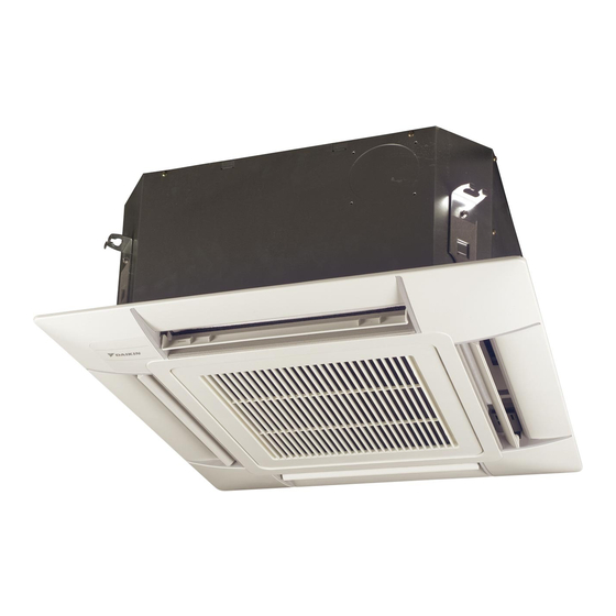
Cover
Cover
Type numbers
INSTALLATION MANUAL
Fan coil units
Table of
Contents
Previous
Page
Next
Page
1
2
3
4
5
Advertisement
Table of Contents
Need help?
Do you have a question about the FWF02B7TV1B and is the answer not in the manual?
Ask a question
Questions and answers
Related Manuals for Daikin FWF02B7TV1B
Ventilation Daikin D-Series Service Manual
(479 pages)
Ventilation Daikin UHH Installation Instructions Manual
Steam/hot water unit heaters installation instructions for horizontal air delivery model uhh and vertical air delivery model udh (24 pages)
Ventilation Daikin VAM350J7VEB Installer And User Reference Manual
Heat reclaim ventilation unit (49 pages)
This manual is also suitable for:
Fwf03b7tv1b
Fwf04b7tv1b
Fwf05b7tv1b
Fwf02b7fv1b
Fwf03b7fv1b
Fwf04b7fv1b
...
Show all
Fwf05b7fv1b
Table of Contents
Print
Rename the bookmark
Delete bookmark?
Delete from my manuals?
Login
Sign In
OR
Sign in with Facebook
Sign in with Google
Upload manual
Upload from disk
Upload from URL


Need help?
Do you have a question about the FWF02B7TV1B and is the answer not in the manual?
Questions and answers