
Related Manuals for LTV LTV-ISDNO20-EM2

Summary of Contents for LTV LTV-ISDNO20-EM2
-
Page 1: User Manual
IP Speed Dome Camera User Manual Please read this instruction carefully for correct use of the product and preserve it for reference purposes... - Page 2 Disclaimer This manual is provided for user reference only, without legal restraint. This content of this manual is subject to change without prior notice, and the updates will be added into the new version of this manual. This manual may contain several technically incorrect places or printing errors, please feel free to let us know.
- Page 3 Notes on Safety Please use the specified power supply to connect (supports AC24V). Do not attempt to disassemble the camera; in order to prevent electric shock, do not remove screws or covers. There are no user-serviceable parts inside.
-
Page 4: Table Of Contents
Contents Introduction ..................1 Chapter 1 Installation ..................2 Chapter 2 IE Connection ................... 6 Chapter 3 3.1.1 Too l ...... - Page 5 4.3 Snap ...................... 12 Chapter 5 Menu Setup ..................13 System ..................Setup 13 p 13 5.1.1............... y 14 5.1.2............y 14 5.1.3..............5.1.4................H 14 5.1.5............
- Page 6 n 14 5.1.6.............. Camera .................Setup 14 l 15 5.2.1..............I 15 5.2.2................
- Page 7 t 16 5.2.3..............d 16 5.2.4................ 5.2.5................t 17 5.2.6..............Dome ................Function 17...
- Page 8 p 17 5.3.1................ p 18 5.3.2................p 19 5.3.3................ p 20 5.3.4................. & N 20 5.3.5...............
- Page 9 Load ...................Default 21 Chapter 6 Remote................Configuration 22 System ..............Configuration 22...
- Page 10 Basic Information ............... 22 6.1.1 Date & Time Configuration ..........22 6.1.2 SD Card ................23 6.1.3 Video Configuration ............... 23 Camera Configuration ............24 6.2.1 Video Stream ..............24 6.2.2 Time Stamp ................ 24 6.2.3 PTZ Configuration................25 Preset Configuration ............25 6.3.1 Cruise Configuration ............
- Page 11 6.6.6 Up g r a d e ................
-
Page 12: Introduction
Chapter 1 Introduction Chapter 1 Introduction 1.1 Overview This IP speed dome camera is front-end equipment used for video capture. Its digital flip technology makes omni-directional and non-blind-spot monitoring into reality. It utilizes most advanced technologies, such as video encoding and decoding technology, and complies with the TCP/IP protocol, SoC., etc, to ensure this system more stable and reliable. -
Page 13: Installation
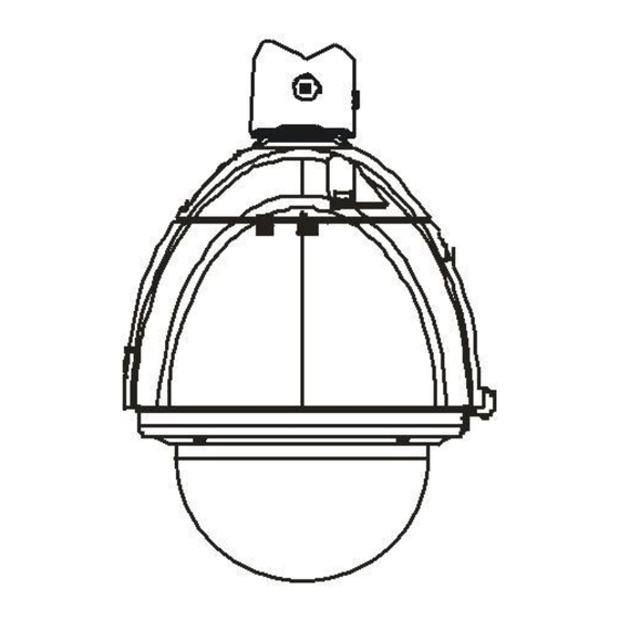
Chapter 2 Installation Chapter 2 Installation Install IP Speed Dome Camera Caution: Please make sure the wall is able to bear the dome camera‘s weight. Please make sure the dome camera is powered off during installation. The installation steps are as follows: Step 1: Disassemble the dome camera. - Page 14 Chapter 2 Installation Make the arrow of ―START‖ point to the bending part of the spring leaf as shown in ① Fig 6. ② Hook the steel wire on the frame as shown in Fig 7. Steel Wire (Fig 6) (Fig 7) ③...
- Page 15 Chapter 2 Installation ALM IN/OUT IN 1 IN 2 IN 3 IN 4 OUT1 OUT2 wer Su Power Connection AC 24V Alarm Connection: Alarm Input: There are four independent alarm input ports (ALM-IN1~4) and one common port (ALM-COM). Connect DC 5V~DC12V voltage between the alarm input port ALM-In x (x=1~4) and the common port (ALM-COM).
-
Page 16: Cms Installation
Chapter 2 Installation Whether to Connection between OUT1 and Output Mode output OUT 2 Open Circuit NO Output Short Circuit Short Circuit NC Output Open Circuit Examples: Input Connection Output Mode Output Connection No Alarm Input Alarm Input CMS Installation Find CMS software from CD and then double click ―Setup.exe‖... -
Page 17: Ie Connection
Chapter 3 IE Connection Chapter 3 IE Connection IP-Cam can be connected through LAN or WAN. Here only take IE browser (6.0) for example. The details are as follows: 3.1 LAN In LAN, there are two ways to access IP-CAM:① Access through IP-Tool;② Directly Access through IE Browser. -
Page 18: Directly Access Through Ie
Chapter 3 IE Connection For example, the IP address of this computer is 192.168.13.57. So, please modify the IP address and Gateway of the IP-Cam which must be in the same local network with the computer‘s. After modifying, please input the user name and password and then click ―OK‖... - Page 19 Chapter 3 IE Connection Gateway: 192.168.226.1 HTTP: 80 Data port: 9008 The first you used the network speed dome, you should connect the device with the above default settings. Step 1: Manual setup the IP address of the PC, the network segment should be as same as the default settings of IP-CAM.
- Page 20 Chapter 3 IE Connection 3.2 WAN Access through router or virtual server Step1: Connecting according above steps LAN; Enter into System Configuration Network configuration Basic configuration to setup the port number as shown in the picture on the left hand. ...
-
Page 21: Remote Preview
Chapter 4 Remote Preview Chapter 4 Remote Preview 4.1 Remote Preview After you log in, you will see the following window. The descriptions of the icon on the remote preview interface: Icon Description Icon Description Motionalarm Sensor alarm indicator indicator icon icon Fix size Start/Stop record... -
Page 22: Playback
Chapter 4 Remote Preview Click PTZ extended button to unfold PTZ control panel. In remote preview interface, you can view the image from every direction by controlling PTZ panel. The descriptions of the control panel are as follows: Button Description to rotate the dome upwards;... -
Page 23: Snap
Chapter 4 Remote Preview After selecting the record date, the record files will be displayed in the record file list box. Double click a certain record file to playback or check a certain file. Then click Play button to play. 4.3 Snap Select the picture number and then click ―Snap‖... -
Page 24: Chapter 5 Menu Setup
Chapter 5 Menu Setup Chapter 5 Menu Setup Under the PTZ control panel of IE remote preview interface, click number 9 and 5 and then click [Call] button to Call No.95 preset. Now, you can see main menu setup as shown below. After you enter the main menu interface, you can select the menu by clicking the direction button ( :To select menu by moving up and down. -
Page 25: Camera
Chapter 5 Menu Setup After you exit the main menu, press and hold button to let the speed dome move to the bottom so that the dome will auto flip. 5.1.2 Temperature Display After enabling temperature and exiting the main menu setup, the temperature will display on the remote preview image. - Page 26 Chapter 5 Menu Setup 5.2.1 Camera Control 【BLC】:When the background light is so stronger that the foreground is dark, the brightness of the whole image will improve thereby enhancing the visibility of the foreground image if the BLC function is enabled. 【HLC】:...
-
Page 27: Zoom Speed
Chapter 5 Menu Setup 【Brightness】:Range from 0(darkest)~20(brightness). 【AGC】:The larger the number is, the higher the brightness and the more the noises of the image are. 【Shutter Mode】:Two modes can be optional. Manual & Auto. 【Shutter】:The lower the value of camera shutter is, the brighter the image is. It is available only when the shutter mode is set to manual mode. -
Page 28: Dome
Chapter 5 Menu Setup 5.2.6 Video Format To choose video format: PAL or NTSC. 5.3 Dome Function Dome function includes five sub-menus: Patrol Setup, Task Setup, Alarm Setup, Trace Setup, Day Night. 5.3.1 Patrol Setup Enter Main Menu Dome Function Patrol Setup as below: In this interface, by programming presets in patrol list in advance, the system will keep calling... - Page 29 Chapter 5 Menu Setup Set the preset and time. The preset ranges from 001 to 255 and the dwell time is from 05s to 240s. Step 3: Run the current patrol. The camera will automatically keep running according to the patrol you set until new command is received.
-
Page 30: Alarm Setup
Chapter 5 Menu Setup 5.3.3 Alarm Setup Enter Main Menu Dome Function Alarm Setup as shown below: Setting Steps: Step 1: Enable ―IN1 Alarm‖. This means the first channel is allowed to input alarm, otherwise it is prohibited to input alarm. Step 2: Select the preset that the system will call on IN1 alarm. -
Page 31: Trace Setup
Chapter 5 Menu Setup Alarm Priority: The higher the channel number is, the lower the priority level is. For example, IN 1 Alarm is higher than IN2 Alarm, so on and so forth. If high priority channel and low priority channel trigger alarm simultaneously, the preset of the latter will not be called, but if you have set the alarm output for the latter, its alarm information will be displayed. -
Page 32: Load
Chapter 5 Menu Setup Enable ―Day & Night‖ and respectively set the B/W time and color time. Call preset 1 to save the setting. Then the camera will automatically switch from B/W to color at the set time. Note: Day &... -
Page 33: Basic Information
Chapter 6 Remote Configuration Chapter 6 Remote Configuration Functions of remote configurations include: System Configuration, Video Configuration, PTZ Configuration, Alarm Configuration, Network Configuration and Advanced Configuration. You should firstly select the menu on the left, and then setup the relative parameters. When one user configures parameters of a certain device, other users can not setup this device. -
Page 34: Sd Card
Chapter 6 Remote Configuration 2. Select ―Modify Time " to self-define time. Choose "Time Zone" according to your location. 3. Enable DST and set DST mode and time. 4. Setup time by selecting the ―Synchronize with NTP Server‖. 5. Press the "Save" button to save the settings. 6.1.3 SD Card Setting steps: ... -
Page 35: Camera Configuration
Chapter 6 Remote Configuration Time Stamp. 6.2.1 Camera Configuration Setting steps: 1. Enter into "Video Configuration " "Camera" interface as shown below: 2. Adjust Brightness, Contrast, Hue and saturation of the picture. 3. Select white balance mode. 4. Sharpen, denoise, frequency and CVBS format are adjustable. 5. -
Page 36: Ptz Configuration
Chapter 6 Remote Configuration Here you can set date format and the position of the time stamp shown in the live image. 6.3 PTZ Configuration PTZ Configuration includes three submenus: Preset, Cruise and Update PTZ Configuration. 6.3.1 Preset Configuration 1. -
Page 37: Cruise Configuration
Chapter 6 Remote Configuration 6.3.2 Cruise Configuration Enter into "PTZ Configuration" "Cruise" to display an interface as shown below: There are 8 cruise lines by default. Choose a cruise and click ―Modify‖ button to pop up a window as below: You can add 16 presets into this cruise at most. -
Page 38: Alarm Configuration
Chapter 6 Remote Configuration Acquire the upgrade software from the supplier and save it in your PC. Then click ―Browse‖ button here to find your upgrade software and then click ―Update PTZ‖ button to upgrade. 6.4 Alarm Configuration Alarm configuration includes six submenus: Motion Detection Area, Motion Detection Trigger, Motion Detection Schedule, Alarm Input Trigger, Alarm Input Schedule and Alarm Out. -
Page 39: Motion Detection Schedule
Chapter 6 Remote Configuration 3. Set alarm holding time. 4. Set alarm trigger options. Alarm Out: If selected, this would trigger the external relay output on detecting a motion based alarm. Trigger Snap: If selected, the system will snap images on an alarm and save them in SD card. Trigger Email: If the email and attach picture checkbox is checked (Email address shall be set first in the Mail config interface), the triggered snap pictures and event will be sent into those addresses. -
Page 40: Alarm Input Trigger
Chapter 6 Remote Configuration Week schedule Set the alarm time from Monday to Sunday for alarm everyday in one week. Note: The lengthwise means one day of a week; the rank means 24 hours of a day. Mouse clicks on the pane to set the alarm hours. Green means selected area. Blank means unselected area. -
Page 41: Alarm Out
Chapter 6 Remote Configuration 1. Select the sensor at the "Sensor" pull down list 2. The following setup steps are similar to Motion Detection Schedule‘s. Please refer to Motion Detection Schedule chapter for more details 6.4.6 Alarm Out 1. Enter into ―Alarm configuration" "Alarm output"... -
Page 42: Wired
Chapter 6 Remote Configuration 2. Input port number for IE access in the "HTTP Port" textbox. 3. Input the port number for audio & video transmission in the "Data Port" textbox. 6.5.2 Wired 1. Enter into "Network Configuration" "Wired" to see a tab shown below: 2. -
Page 43: Ip Notify
Chapter 6 Remote Configuration 1. Check ―Do you want IP Camera to connect Server. 2. Check the IP address and port of the transfer media server in the ECMS/NVMS. Then enable the auto report in the ECMS/NVMS when adding a new device. Then input the remaining information of the device in the ECMS/NVMS. - Page 44 Chapter 6 Remote Configuration Note: The steps to band a domain name for video surveillance server are as follows. Firstly, register a user name and a password to log on the website of service supplier, and then apply for a domain name online for the server. After that, you can visit the server through inputting the domain name at IE terminal.
-
Page 45: Rtsp
Chapter 6 Remote Configuration Log in Domain Setup Step 1: Click "Domain Management" on the left to set the domain. Domain setup Step 2: Input the domain in the textbox. For example, you set ‗IP-CAMERA‘ as the domain. Step 3: Click "Submit" button, the system will pop up a dialog box to show that the domain is added successfully. -
Page 46: Upnp
Chapter 6 Remote Configuration 1. Select ―Enable RTSP server. 2. RTSP Port: Access Port of the streaming media. The default number is 554. 3.RTSP Address: The RTSP address you need to input in the media player. 4. Check ―enable anonymous viewer login…‖. Application: This device supports VLC player. -
Page 47: Mail Setting
Chapter 6 Remote Configuration If ―Show icons for networked UPnP devices‖ can‘t display in the ―Network Tasks‖ list box, please follow the below operation: Click ―Tools‖-- ―Folder options‖ Check the ―Show common tasks in folders‖ in the ―Tasks‖ check box, UPnP icon will display. 6.5.8 Mail Setting ... -
Page 48: Advanced Configuration
Chapter 6 Remote Configuration 1. Add: Click Add button to input FTP server‘s server name, address, port number, user name, password, and upload path, click OK to confirm the setting. Refer to the following picture: Modify: Your can click this button to change some information of the FTP server Delete: Select certain FTP account;... - Page 49 Chapter 6 Remote Configuration After binding physical address to the IP-CAM, you can access the device on this PC only. If the MAC address was ――00:00:00:00:00:00‖ which means it can be connected to any computers. 2. Input user name in "User Name" textbox (only letters). 3.
-
Page 50: Onvif Configuration
Chapter 6 Remote Configuration Parameter Meaning User Name User name to operate the logon client end User Type Type of users, normal user, advanced user and super administrator The MAC addresses of user access the server which should setup Binding MAC address according to actual MAC address of server. -
Page 51: Configure Backup & Restore
Chapter 6 Remote Configuration Check ―Enable MAC address‖ check box, select ―Deny the following IP address‖, input MAC address in the MAC address list box and click ―Add‖ button. Then this MAC address will display in the list box; the operation step of ―Allow the following MAC address‖ is the same with ―Deny the following IP address‖. - Page 52 Chapter 6 Remote Configuration 1. Click ―Browse‖ button to select the save path of the upgrade file 2. Click ―Upgrade server firmware‖ button to start upgrading the application program 3. The device will restart automatically 4. After you successfully update the software, click ―OK‖ button to close IE and then re-open IE to connect IP-Cam.
-
Page 53: Chapter 7 Video Search
Chapter 7 Video Search Chapter 7 Video Search Click ―Picture‖ icon and search the images which saved in the SD card. Set time: Select date in the ―calendar‖ and choose the start and end time. Choose event ―Motion‖ or ―Sensor‖. Click ―Search‖... - Page 54 Chapter 7 Video Search Item Buttons Explanations Close: Select certain picture and click this button to close this picture. Close all: Click this button to close all pictures viewing. Save: Click this button to select the save path of the picture file on the PC for saving the current picture.
-
Page 55: Chapter 8 Mobile Surveillance
Chapter 8 Mobile Surveillance Chapter 8 Mobile Surveillance This IP-CAM supports mobile surveillance by phones with Windows mobile, iPhone, Android and Blackberry OS. Please check the operation system version of mobile before use; and connect the IP-CAM to Internet. 8.1 Network Configuration ... - Page 56 Chapter 8 Mobile Surveillance Step 3: Click ―Install App‖ button as shown in the figure on the left. Step 4: Input iTunes Store password and then click ―OK‖. The software will be installed automatically. Install Software through PC Step 1: Install iTunes store in PC and then login.
- Page 57 Chapter 8 Mobile Surveillance Step 3: Search ―SuperLivePro‖ and select it. Step 4: Click ―Download‖ button. Step 5: Input username and password. IP-CAMERA User Manual - 46...
- Page 58 Chapter 8 Mobile Surveillance Step 6: Synchronously apply SuperLivePro software to iPhone/iPad. SuperLivePro Instruction Login IP-CAMERA User Manual - 47...
- Page 59 Chapter 8 Mobile Surveillance Step 1: Choose network type. There are two network connection ways: 3G/3G +WIFI, well video quality. This network supports main stream and sub stream. The real-time image will be displayed by using sub stream. 3G-, poor video quality contrast to the above mentioned network. Step 2: Input server, account and password.
- Page 60 Chapter 8 Mobile Surveillance :Help button. Help you know about the use of this software quickly. :CMS button. Make you preview the live image of multi-devices. :Log off button. Click this button to return to the login interface. :Screen mode button. You can choose 1,4,6,8,9, 13 or 16 screen display mode.
- Page 61 Chapter 8 Mobile Surveillance Delete device: Click button behind the device name to delete this device. Edit device: Click button behind the device name to edit the information of this device. Backup & restore: It is recommended to click【Backup】button to reserve the information of all devices.
- Page 62 Chapter 8 Mobile Surveillance Fig 1 Fig 2 Fig 3 Fig 4 Fig 5 CMS Function This function makes multi-device managements and preview come true. Step 1: Click to enable CMS function. When this icon turns green, it means this function is enabled.
- Page 63 Chapter 8 Mobile Surveillance If channels have been added into the group, you can see the images by clicking the group name. On viewing the group channel images, click button and select channels to check other ...
- Page 64 Chapter 8 Mobile Surveillance Image View Click button to view the captured pictures. Settings Interface In this interface, you can configure the local settings. 10. Information Interface IP-CAMERA User Manual - 53...
-
Page 65: By Phones With Android Os
Chapter 8 Mobile Surveillance In this interface, you can view system information. 8.3 By Phones with Android OS Software Installation Step 1: Run ―Play Store‖ (or Google market) program. Step 2: Search ―SuperLivePro‖. IP-CAMERA User Manual - 54... - Page 66 Chapter 8 Mobile Surveillance Step 3: Press ―Install‖ button. Step 4: Install the software subject to the notes. Once the downloading is done, the software will install automatically. Login Step 1: Configure the network of your device and mobile phone. Step 2: Input the WAN IP address/domain name and port of your device in the sever column.
- Page 67 Chapter 8 Mobile Surveillance Live View Snap Record Talk Enable/disable audio Hide Playing favorite channel Image View The first picture The previous picture Next picture The last picture Zoom in Zoom out Delete IP-CAMERA User Manual - 56...
- Page 68 Chapter 8 Mobile Surveillance Record Playback Click ―Playback‖ in the main menu interface to enter playback interface. Then choose the channel you want to playback. This will take you to see the record file. Click this file to play. Pause/Play Stop Forward Backward...
- Page 69 Chapter 8 Mobile Surveillance In the main menu interface, click ―Server list‖ to see the above picture on the left hand. Add Server: Click button to pop up a window as shown in the above picture on the right hand. Enter the name, server, user and password of the device you want to add. Then click 【 Save】button to save the server.
-
Page 70: Chapter 9 Ip-Tool
Chapter 9 IP-Tool Chapter 9 IP-Tool Updating through IP-Tool Note: Do not cut off power supply and internet when updating; If the device is unable to start because of the failure of upgrade, it needs to retrofit. Modify IP address Acquire the IP-Tool from the supplier and then double click the IP-Tool icon to run this software. - Page 71 Chapter 9 IP-Tool Modify IP address and click OK button to exit the dialog box. After that, IP-Tool will display the new IP address. Upgrade Software Select the device; right click ―Update software‖. Click ―Update‖ to start upgrading,the progress bar will display as below.
- Page 72 Chapter 9 IP-Tool Input the relevant information and click ―Browse‖ button to choose your update file. After that, click ―Update Kernel‖ button to start updating. When upgrading, do not disconnect PC to device and make sure the power is on. The update progress bar will display as below: After finishing upgrading, a message box will pop up.
-
Page 73: Chapter 10 Q & A
Chapter 10 Q & A Chapter 10 Q & A 1. Q: I forget the password. How can I do? A:Joint the default line and GND line to reset. Default IP: 192.168.226.201 User name: admin Password: 123456 2. Q:The devices can’t connect through IE browser. Why? A: ○... - Page 74 Chapter 10 Q & A Fig 4-1 Fig 4-2 ④ then click ok to finish setup. Other plug-ins or anti-virus blocks ActiveX. Please uninstall or close them. 5. Q:Why can’t the device sound? A:Without connect audio input device. Please connect and try again. Without enable audio function at the corresponding channel.
-
Page 75: Chapter 11 Specification
Chapter 11 Specification Chapter 11 Specification Model 2 Mega Pixel High Speed IP Camera Image Sensor 1/3‖ CMOS Effective Pixel 1920 x 1080 Horizontal Resolution 1000TVL Low Illumination 0.5 Lux (Day), 0.1Lux(Night), 0.005Lux(DSS ON) 20xZoom, f = 4.7~94mm, F1.6~F3.5 Lens 12 xZoom, f = 5.3~62.6mm, F1.8~F2.1 Pan Range 360°... -
Page 76: Appendix Preset
Appendix Preset Description Appendix Preset Description Call NO.90 Preset Run trace 1 Call NO.91 Preset Run patrol 1 Call NO.92 Preset Run patrol 2 Call NO.93 Preset Run patrol 3 Call Preset Call NO.94 Preset Run patrol 4 Call NO.95 Preset OSD menu Call NO.97 Preset Enable random scan...
Need help?
Do you have a question about the LTV-ISDNO20-EM2 and is the answer not in the manual?
Questions and answers