Table of Contents
Advertisement
Quick Links
DECEMBER 1995
IC713A
IC713AE
G.703 Codirectional Converter
r
v e r t e
l C o n
t i o n a
d i r e c
3 C o
G . 7 0
A N A
D I G
T
T E S
L O S
R D
T D
P W R
CUSTOMER
Order toll-free in the U.S.: Call 877-877-BBOX (outside U.S. call 724-746-5500)
SUPPORT
FREE technical support 24 hours a day, 7 days a week: Call 724-746-5500 or fax 724-746-0746
INFORMATION
Mailing address: Black Box Corporation, 1000 Park Drive, Lawrence, PA 15055-1018
Web site: www.blackbox.com • E-mail: info@blackbox.com
Advertisement
Table of Contents

Related Manuals for Black Box G.703


Summary of Contents for Black Box G.703
- Page 1 Order toll-free in the U.S.: Call 877-877-BBOX (outside U.S. call 724-746-5500) SUPPORT FREE technical support 24 hours a day, 7 days a week: Call 724-746-5500 or fax 724-746-0746 INFORMATION Mailing address: Black Box Corporation, 1000 Park Drive, Lawrence, PA 15055-1018 Web site: www.blackbox.com • E-mail: info@blackbox.com...
- Page 2 FCC STATEMENT FEDERAL COMMUNICATIONS COMMISSION INDUSTRY CANADA RADIO FREQUENCY INTERFERENCE STATEMENTS This equipment generates, uses, and can radiate radio-frequency energy, and if not installed and used properly, that is, in strict accordance with the manufacturer’s instructions, may cause interference to radio communication. It has been tested and found to comply with the limits for a Class A computing device in accordance with the specifications in Subpart B of Part 15 of FCC rules, which are designed to provide reasonable protection against such interference when the equipment is...
- Page 3 G.703 CODIRECTIONAL CONVERTER NORMAS OFICIALES MEXICANAS (NOM) ELECTRICAL SAFETY STATEMENT INSTRUCCIONES DE SEGURIDAD 1. Todas las instrucciones de seguridad y operación deberán ser leídas antes de que el aparato eléctrico sea operado. 2. Las instrucciones de seguridad y operación deberán ser guardadas para referencia futura.
- Page 4 NOM STATEMENT 12. Precaución debe ser tomada de tal manera que la tierra fisica y la polarización del equipo no sea eliminada. 13. Los cables de la fuente de poder deben ser guiados de tal manera que no sean pisados ni pellizcados por objetos colocados sobre o contra ellos, poniendo particular atención a los contactos y receptáculos donde salen del aparato.
- Page 5 G.703 CODIRECTIONAL CONVERTER TRADEMARKS USED IN THIS MANUAL Any trademarks mentioned in this manual are acknowledged to be the property of the trademark owners.
-
Page 6: Table Of Contents
Page 1. Specifications ....................6 2. Introduction ....................8 2.1 Functional Description ..............8 2.2 Timing Theory ...................9 2.2.1 CCITT G.703 Signalling ............9 2.2.2 G.703 Codirectional Timing..........10 2.2.3 Tail-End Clocking ..............14 2.2.4 G.703 Codirectional Rules.............14 2.3 Rate-Conversion Rules ..............16 2.4 Physical Description .................16 3. -
Page 7: Specifications
G.703 CODIRECTIONAL CONVERTER 1. Specifications G.703 I NTERFACE Type — Codirectional 64-kbps 4-wire, 19- to 26-gauge Line — Range — Up to 800 meters ( ⁄ mile) over 24-gauge wire Impedance — 120 ohms nominal Balance — Better than 45 dB (up to 256 kHz) Better than 35 dB (up to 384 kHz) Return Loss —... - Page 8 RTS OFF, or during Loss of Signal condition; DSR output: ON (+V) when power is available Clock Source — From G.703 Receive pair (LBT), from DCE (EXT), or from internal source (INT), user-selectable Data Polarity — Normal (MARK = “0”) or inverted (MARK = “1”),...
-
Page 9: Introduction
Converter. The Converter can act as a data-rate adapter, allowing you to connect DTEs running at 48 or 56 kbps to a 64-kbps G.703-interface line. At 48 or 56 kbps, you can set another jumper to select any one of these ways to use the extra bandwidth: •... -
Page 10: Timing Theory
2.2 Timing Theory 2.2.1 CCITT G.703 S IGNALING The CCITT G.703 codirectional signal is made up of two balanced signals: The receive and transmit signals carry timing and data information. The clock signal associated with each direction of transmission travels... -
Page 11: Codirectional Timing
G.703 Receive Timing Used for G.703 Transmit Timing When G.703 receive timing is used for G.703 transmit timing, three timing options for the data-communication side, associated with the loopback timing (LBT) on the G.703 side, are available:... - Page 12 CHAPTER 2: Introduction G.703 Codirectional Converter Figure 2-2. G.703 Codirectional Converter signaling. G.703 Codirectional Converter Figure 2-3. LBT-DTE Connection. G.703 Codirectional Converter Figure 2-4. LBT-DCE21 Connection.
- Page 13 Figure 2-6 shows this timing mode. Internal-Clock Timing Mode The Converter’s internal oscillator is usually used as the source for G.703 transmit timing for testing purposes only, but can also be used with systems that do not have a clock source. Figure 2-7 shows this timing mode.
- Page 14 CHAPTER 2: Introduction G.703 Codirectional Converter Figure 2-6. Transmit Clock Timing Mode. G.703 Codirectional Converter Figure 2-7. Internal Clock Timing Mode.
-
Page 15: Tail-End Clocking
If necessary, the bit stream from the DTE can be inverted prior to the conversion to G.703. (The binary signal being sent to the DTE is inverted at the same time.) You can turn this data inversion on or off, as appropriate... - Page 16 CHAPTER 2: Introduction G.703 Codirectional Converter Figure 2-8. Tail Circuit Application. Figure 2-9. G.703 Code Conversion.
-
Page 17: Rate-Conversion Rules
MARK = “1” setting. 2.4 Physical Description The G.703 Codirectional Converter is a standalone unit. The unit is designed for installation on top of a bench or a shelf, but can also be mounted on a 19-inch rack with the proper adapter kit. -
Page 18: Installation
3.1 Unpacking Unpack the equipment this way: • Carefully take the G.703 Codirectional Converter out of the box it came in and place the Converter on a clean surface. • Inspect the unit for damage. Immediately report any damage you find to your carrier and supplier. - Page 19 G.703 CODIRECTIONAL CONVERTER Figure 3-1. G.703 Codirectional Converter Board Layout.
- Page 20 Disconn Disconn: Protective ground disconnected from signal ground. TC G.703 LBT The Tx-pair timing is the recovered clock from the CCITT G.703 Rx pair. The Tx-pair and transmit timing are from the RS-422/V.35 external source. The Tx-pair and transmit timing are from the internal source.
-
Page 21: The Jumper-Setting Procedure
3.4.1 O VERVIEW The G.703 Codirectional Converter can be installed in 19-inch racks. It is 1U (1.75", 4.4 cm) high and is slightly less than half as wide as the available mounting area. Two rack-adapter kits are available: One kit provides the hardware necessary to install a single unit, and the other provides the hardware necessary to install two units side by side. -
Page 22: Installing A Single Unit In A 19-Inch Rack
CHAPTER 3: Installation 3.4.2 I NSTALLING A INGLE NIT IN A INCH The rack-adapter kit for single-unit installation includes one short bracket and one long bracket. The brackets are fastened with screws to the two side walls of the case, as shown in Figure 3-2. To prepare the Converter for rack installation, attach the two brackets to the sides of the unit. -
Page 23: Installing Two Units In A 19-Inch Rack
G.703 CODIRECTIONAL CONVERTER 3.4.3 I 19-I NSTALLING NITS IN A The adapter kit includes two adapter brackets and various hardware for attaching two Converters side by side in a 19-inch rack. Refer to Figure 3-3 when you perform the following procedure: 1. - Page 24 CHAPTER 3: Installation Figure 3-3. Installing two units in a 19-inch rack.
-
Page 25: Connecting Power And Data Cables
DCE (for more detailed information, refer to the Appendix). The terminal block has five screws for connecting transmit and receive CCITT G.703 lines—the transmit pair where XMT is indicated, and the receive pair where RCV is indicated. Connect power and data cables to the Converter as described in the following subsections. -
Page 26: Power Connection
3.5.2 G.703 LINE C ONNECTION The G.703 LINE connection provides an interface for the TX and RX signals between the Converter and G.703 line equipment. To make this connection, attach the wires from the line equipment to the terminal block on the Converter this way: •... -
Page 27: Dte Connection
NOTE You can use an async secondary channel only when you run a primary channel at 56 or 48 Kbps on a clear channel, and you must have a G.703 Codirectional Converter at both ends of the link. The rules for operation with an asynchronous sub-channel are: •... -
Page 28: Operation
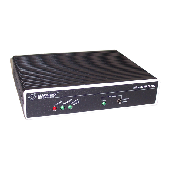
Five LEDs are visible through the front panel (see Figure 4-1). Each LED’s function is described in Table 4-1. Two pushbuttons are available for activating loops, as described in Table 4-1. G.703 Codirectional Converter Figure 4-1. Front panel of the G.703 Codirectional Converter. - Page 29 G.703 CODIRECTIONAL CONVERTER Table 4-1. Functions of LEDs and Controls. Indicator/Control Function PWR (Green) Lights when the unit is receiving power. Power TD (Yellow) Flickers when data is present at transmit Transmit Data input and goes off when a steady mark is present.
-
Page 30: Operating Instructions
Local analog loopback can also be activated from the local DTE through Pin 18. Activating local analog loopback causes a loop in the local G.703-interface circuit, towards the local data equipment (as shown in Figure 4-2). Activating local digital loopback causes a loop in the local unit on the... - Page 31 G.703 CODIRECTIONAL CONVERTER G.703 Codirectional Converter Figure 4-2. Local analog loopback. G.703 Codirectional Converter Figure 4-3. Local digital loopback.
-
Page 32: Appendix: Pinouts
APPENDIX: Pinouts Appendix: Pinouts Figures A-1 to A-11 provide connection diagrams for the range of available interfaces and options. Table A-1 provides pin assignments for cable connections. V.35 G.703 (DTE) Codirectional Converter (DCE) Figure A-1. Connection to DTE, V.35 Interface (EHN033). - Page 33 G.703 CODIRECTIONAL CONVERTER V.35 G.703 (DCE) Codirectional Converter (DCE) Figure A-2. Connection to DCE, V.35 Interface (for tail circuit application) (EHN034).
- Page 34 APPENDIX: Pinouts G.703 V.35 Codirectional Connector Converter V.35 25-Pin Connector Figure A-3. V.35 With Secondary Channel Cable (EY-2364-C).
- Page 35 G.703 CODIRECTIONAL CONVERTER X.21 G.703 (DTE) Codirectional Converter (DCE) Figure A-4. Connection to DTE, X.21 Interface (EHN035).
- Page 36 APPENDIX: Pinouts G.703 Codirectional X.21 Converter (DCE) (DTE) Figure A-5. Connection to DCE, X.21 Interface (EHN036).
- Page 37 G.703 CODIRECTIONAL CONVERTER V.36 G.703 (DTE) Codirectional Converter (X.21-DCE) RS-449 (DTE) 37-Pin Figure A-6. Connection to DTE, V.36/V.11 Interface (connection to DTE, RS-449/RS-422 interface)(EHN037).
- Page 38 APPENDIX: Pinouts V.36 (DCE) G.703 Codirectional Converter RS-449 (DCE) (DCE) 37-Pin Figure A-7. Connection to DCE, V.36/V.11 Interface (connection to DCE, RS-449/RS-422 interface for tail circuit applciation) (EHN038).
- Page 39 G.703 CODIRECTIONAL CONVERTER G.703 V.36 Codirectional Connector Converter V.11 25-Pin Connector Figure A-8. V.36 With Secondary Channel Cable (EY-2364-B).
- Page 40 APPENDIX: Pinouts G.703 RS-530 Codirectional Converter (25-Pin) (DCE) Figure A-9. Connection to DTE, RS-530 Interface (EHN039).
- Page 41 G.703 CODIRECTIONAL CONVERTER RS-530 G.703 (DCE) Codirectional 25-Pin Converter (DCE) Figure A-10. Connection to DCE, RS-530 Interface (for tail circuit application) (EHN040).
- Page 42 APPENDIX: Pinouts G.703 RS-530 Codirectional Connector Converter V.11 25-Pin Connector Figure A-11. RS-530 With Secondary Channel Cable (EY-2364-D).
- Page 43 G.703 CODIRECTIONAL CONVERTER Table A-1. Cable Connections. IC713 RS-449 RS-449 V.35 V.35 X.21 X.21 Function 25-PIN 37-PIN 37-PIN 34-PIN 34-PIN 15-PIN 15-PIN Frame Ground 1 (1) Signal Ground 7 (7) 19,20,37 19,20,37 TX Data A 2 (9) TX Data B...
- Page 44 © Copyright 1995. Black Box Corporation. All rights reserved. 1000 Park Drive • Lawrence, PA 15055-1018 • 724-746-5500 • Fax 724-746-0746...
Need help?
Do you have a question about the G.703 and is the answer not in the manual?
Questions and answers