Table of Contents
Advertisement
Quick Links
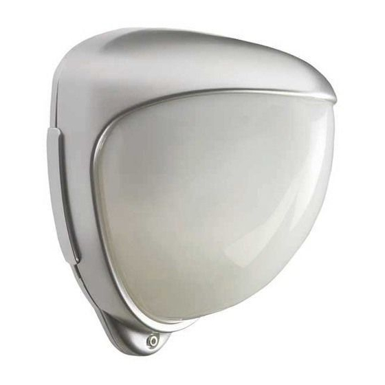
D-TECT X 40 MKIII
GJD440 40m Wireless Detector
D-T ect X MKIII Wireless Detector
GJD440 Battery Powered Quad PIR
Package contents
Package Contains:
•
1 x D-Tect X MKIII Wireless Detector
•
1 x Drilling template for fixing holes
•
3 x 31.75mm wall plugs
•
3 x 31.75mm screws
•
2 x Additional sliding curtains
•
2 x Tamper feet
•
1 x Installation manual
•
1 x Self-adhesive lens mask
•
1 x Opening tool
•
1 x Tamper cup
Introduction
The D-Tect X MKIII Wireless Detector is a battery powered
outdoor motion detector that uses two independent passive infra-
red detectors, both of which must trigger to cause the detector to
signal an alarm. Utilising quad PIR technology, the D-Tect X MKIII
Wireless PIR delivers precise, reliable presence detection.
The detector is a battery powered device with an integral 868
MHz transmitter to communicate with GJD D-Tect X Receivers /
Expanders.
Each D-Tect X 40 MKIII detector transmits radio signals to the
receiver and has over 16.7 million individual codes. The receiver
only responds to the transmissions of the detector that has been
linked to the channel that identifies it. The receiver can only
analyse this information after the individual codes have been
transferred via the secure wire code learning link.
Quick Installation
1.
Fit the 2 x CR123 3 volt batteries observing the correct
polarity. The red LED will flash.
2.
Link the detector on to the receiver, using instructions in
the 'Code Learning' section.
3.
Mount the detector following the instructions given later
in this sheet.
4.
Wait approximately 2 to 3 minutes to allow the detector
to settle.
5.
Press the programming button once to activate walk test
mode. The detection LED is now enabled for 5 minutes.
Note: The front cover must be fitted when walk testing.
The default settings are:
•
Range: 40 metres with 15 minute supervision timer
•
Pulse count: 1
•
Lux level 5
•
Timer 5 seconds
Batteries
Only use CR123 3 V Lithium batteries.
Observe correct polarity when fitting.
Battery safety information
•
Do not put in a fire
•
Do not heat
•
Do not charge
•
Do not short circuit
•
Do not disassemble
•
Only fit batteries of the same type and voltage
To preserve battery life the detector has a 2 minute sleep timer
after a detection. This is reduced to 6 seconds during walk test.
Mounting The Unit
During installation, protect the electronics against water, as
trapped moisture can affect or damage the unit.
1.
Drill the wall to accept the two fixing screws and the
tamper cup if used. See Figure 1. A hole-drilling template
is provided.
Note: We recommend using the tamper cup on uneven wall
2.
Remove the cover assembly by loosening the locking
screw. The cover hinges from the top and lifts out of the
location slot.
3.
Screw the base to the wall ensuring that the tamper pin is
correctly located. To aid installation, two alternative length
tamper feet are provided.
4.
Fit two CR123 3 volt batteries.
Note: Observe correct polarity
5.
When the detector is aligned, connected and programmed
to suit the installation, replace and secure the front cover.
Supervision Timer
The detector has 2 selectable supervision timer settings of 2
minutes or 15 minutes. This can be changed in the detection
range programming option. The first three ranges of 20, 30 and
40 have a 15 minute supervision timer and the second ranges of
20, 30 and 40 have a 2 minute supervision timer.
The 15 minute supervision timer will give longer battery life to
the detector. For existing D-Tect X Receivers and Expanders
the 2 minute supervision timer will need to be selected if the
supervision output on the receiver is being monitored. Receivers
and Expanders with a '15 minute supervision' label can use the
15 minute supervision timer setting.
-1-
surfaces.
Advertisement
Table of Contents

Related Manuals for GJD D-TECT X 40 MKIII


Summary of Contents for GJD D-TECT X 40 MKIII
- Page 1 Remove the cover assembly by loosening the locking screw. The cover hinges from the top and lifts out of the Each D-Tect X 40 MKIII detector transmits radio signals to the location slot. receiver and has over 16.7 million individual codes. The receiver...
- Page 2 To re-set the default settings remove the batteries, wait 10 Multibeam Alignment & Masking seconds, press and hold the program button then re-fit the batteries, the LED will flash rapidly then release the program The PIR circuitry detects changes in heat and movement button.
- Page 3 Changing The Random Code Note: When you conduct a walk test, make sure that the front cover is in place. Do not conduct walk tests with the cover removed. In the unlikely event of another radio signal interfering with and affecting the correct operation of a single RF channel, the D-Tect The range of the detector increases without the protective front X MKIII is able to generate an alternative random code.
- Page 4 Figure 1 Specifications Detection Range Programmable: 20m,30m or 40m Coverage 40 x 4m lens, 13° detection angle, 40m x 8m coverage max. Supervision Selectable 2 or 15 minutes RF Transmission 868 MHz Adjustment 180° pan, 90° tilt Fresnel lens 4 (40 x 4) 12 (40 x 8) zones for each Pyro Pair Customized Optics Double silicon shielded quad...
- Page 5 Figure 3 Side View 40 x 4m 2.8m Figure 4 Top View 40m x 4 84° 2.4m 28° 11.3° 2.4m Figure 5 Top View 40m x 8m 77° 21.5° 14° 29° 2.5m 6.5° 2.5m...
- Page 6 Figure 7 Figure 6 Figure 8 BUTTON...
- Page 7 Engineer Notes Technical: 01706 363990 Sales: 01706 363998 Fax: 01706 363991 Email: info@gjd.co.uk Unit 2, Birch Business Park, Whittle,Lane,Heywood,OL10 2SX...
Need help?
Do you have a question about the D-TECT X 40 MKIII and is the answer not in the manual?
Questions and answers