Table of Contents
Advertisement
Air-cooled Package
Middle Static Pressure Duct unit
MTA-76CRN1 / MOV-76CN1-C
MTA-96CRN1 / MOV-96CN1-C
MTA-120CRN1 / MOV-120CN1-C
MTA-150CRN1 / 2* MOV-76CN1-C
MTA-76HRN1 / MOV-76HN1-C
MTA-96HRN1 / MOV-96HN1-C
MTA-120HRN1 / MOV-120HN1-C
[Введите текст]
Air-cooled package
High Static Pressure Duct unit
Service Manual 2013
MHB-76CRN1 / MOV-76CN1-C
MHB-96CRN1 / MOV-96CN1-C
MHB-76HRN1 / MOV-76HN1-C
MHB-96HRN1 / MOV-96HN1-C
DM13-01.01.16en
Advertisement
Chapters
Table of Contents
Troubleshooting

Subscribe to Our Youtube Channel
Related Manuals for Midea MTA-76CRN1


Summary of Contents for Midea MTA-76CRN1
- Page 1 Air-cooled Package DM13-01.01.16en Air-cooled package Middle Static Pressure Duct unit High Static Pressure Duct unit Service Manual 2013 MTA-76CRN1 / MOV-76CN1-C MHB-76CRN1 / MOV-76CN1-C MTA-96CRN1 / MOV-96CN1-C MHB-96CRN1 / MOV-96CN1-C MTA-120CRN1 / MOV-120CN1-C MHB-76HRN1 / MOV-76HN1-C MTA-150CRN1 / 2* MOV-76CN1-C...
-
Page 2: Table Of Contents
DM13-01.01.16en Air-cooled Package Content Part 1 General Information ..........2 Part 2 Indoor Units ............6 Part 3 Outdoor Units ............ 44 Part 4 Installation ............59 Part 5 Control ............... 92 Service manual... -
Page 3: Part 1 General Information
Air-cooled Package DM13-01.01.16en Part 1 General Information 1. Model Names of Indoor/Outdoor Units ......3 2. External Appearance ............4 3. Nomenclature ..............5 Service manual... -
Page 4: Model Names Of Indoor/Outdoor Units
1. Model Names of Indoor/Outdoor Units 1.1 Model Names of Units with Cooling only: Indoor unit Outdoor unit Capacity Type Power Power Model Model Btu/h supply supply MTA-76CRN1 MOV-76CN1-C 380~415V-3 Mid-static MTA-96CRN1 MOV-96CN1-C N-50Hz pressure duct 380~400V-3 MTA-120CRN1 MOV-120CN1-C N-50Hz type... -
Page 5: External Appearance
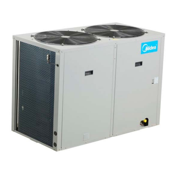
Air-cooled Package DM13-01.01.16en 2. External Appearance 2.1 Indoor Units MTA-76C(H)RN1 MTA-120CRN1\MTA-120HRN1 MTA-96C(H)RN1 MTA-150CRN1 2.2 Outdoor Unit MOV-76C(H)N1-C MOV-96C(H)N1-C MOV-120C(H)N1-C MOV-150C(H)N1-C (MOV-76C(H)N1-C*2) Service manual... -
Page 6: Nomenclature
Product Series A: 1 time design B: 2 time design Indoor Units T: Duct type H: High static pressure Midea 3.2 Outdoor unit: M O V 76 C N1 - C Design times None:R22; N1:R410a Function Code: C: Cooling Only... -
Page 7: Part 2 Indoor Units
Air-cooled Package DM13-01.01.16en Part 2 Indoor Units 1. Features ................7 2. Specifications ..............8 3. Dimensions ............... 11 4. Service Space ..............12 5. Piping Diagrams ............... 14 6. Wiring Diagrams ............... 14 7.Capacity Table ..............19 8. Static Pressure ..............33 9. -
Page 8: Features
DM13-01.01.16en Air-cooled Package 1. Features 1. Nested in the ceiling, space-saving and noble. 2. High capacity of cooling/heating, efficient, and energy-saving. 3. The air outlet is laid out according to you desire. 4. Economic and convenient installation 1) Several diffusers branch off from an indoor unit, adjusting the room temperature, which makes many rooms to be air-conditioned with only one indoor unit. -
Page 9: Specifications
Air-cooled Package DM13-01.01.16en 2. Specifications Model MTA-76CRN1 MTA-76HRN1 MTA-96CRN1 MTA-96HRN1 Power supply 220~240V-1Ph-50Hz 220~240V-1Ph-50Hz Temp. setting range ℃ ≥17 ≤30 ≥17 ≤30 Rated input power 11700 11700 14400 14400 Rated current 19.3 19.3 23.7 23.7 Btu/h 76000 76000 96000 96000... - Page 10 DM13-01.01.16en Air-cooled Package Model MTA-120CRN1 MTA-120HRN1 MTA-150CRN1 MTA-150CRN1 220~240V-1Ph-50Hz Power supply 220~240V-1Ph-50Hz Temp. setting range ℃ ≥17 ≤30 ≥17 ≤30 Rated input power 17300 17300 21200 21200 Rated current 28.6 28.6 120000 120000 Btu/h 150000 150000 Capacity 35000 35000 44000 44000 Cooling Input...
- Page 11 Air-cooled Package DM13-01.01.16en Model MHB-76CRN1 MHB-76HRN1 MHB-96CRN1 MHB-96HRN1 Power supply 220~240V-1Ph-50Hz 220~240V-1Ph-50Hz Temp. setting range ℃ ≥17 ≤30 ≥17 ≤30 Rated input power 11700 11700 14400 14400 Rated current 19.3 19.3 23.7 23.7 Btu/h 76000 76000 96000 96000 Capacity 22000 22000 28000 28000...
-
Page 12: Dimensions
3. Dimensions 3.1 Duct type units with two air outlets: Air inlet side Model A (mm) B (mm) C(mm) E(mm) F(mm) W (mm) H (mm) D (mm) MTA-76CRN1 1180 1350 MTA-76HRN1 MTA-96CRN1 1180 1350 MTA-96HRN1 MHB-76CRN1 1180 1350 MHB-76HRN1 MHB-96CRN1... - Page 13 Air-cooled Package DM13-01.01.16en 3.2 Duct type units with three air outlets: Air inlet side Model B (mm) C(mm) E(mm) F(mm) W (mm) H (mm) D (mm) MTA-120CRN1 794.5 1895 1970 MTA-120HRN1 794.5 1895 1970 MTA-150CRN1 Service manual...
-
Page 14: Service Space
DM13-01.01.16en Air-cooled Package 4. Service Space Electric control box Inspection hole Inspection hole Top view Side view Canvas adapter Muffle Air outlet Muffle Air inlet Inspection hole Air filter Air duct system Service manual... -
Page 15: Piping Diagrams
Air-cooled Package DM13-01.01.16en 5. Refrigerant cycle diagram 5.1 Cooling only: MTA-76CRN1, MTA-96CRN1, MTA-120CR N1, MTA-150CR N1 MHB-76CRN1, MHB-96CRN1 Outdoor heat-exchanger Cooling HP Switch Indoor unit Discharge temp. sensor LP Switch Compressor Indoor heat-exchanger Liquid-gas seperator 5.2 Cooling and heating: MTA-76HRN1, MTA-96HRN1, MTA-120HRN1... -
Page 16: Wiring Diagrams
DM13-01.01.16en Air-cooled Package 6. Wiring Diagrams 6.1 MTA-76CRN1, MTA-96CRN1, MHB-76CRN1, MHB-96CRN1 TO WIRE CONTROLLER CN11 CN10 CN15 MAIN CONTROL BOARD CN20 BLUE WHITE HIGH SLOW BLACK BLUE BLACK WHITE N-LINE WHITE WHITE WHITE WHITE (GRAY) (GRAY) INDOOR POWER TO OUTDOOR... - Page 17 Air-cooled Package DM13-01.01.16en MTA-120CRN1, MTA-150CRN1 TO WIRE CONTROLLER CN11 CN10 CN15 MAIN CONTROL BOARD CN20 WHITE BLUE HIGH SLOW WHITE WHITE BLUE BLACK BLUE WHITE WHITE WHITE WHITE WHITE (GRAY) WHITE (GRAY) (GRAY) INDOOR POWER TO OUTDOOR Item Name Item Name Item Name...
- Page 18 DM13-01.01.16en Air-cooled Package 6.2 MTA-76HRN1, MTA-96HRN1, MHB-76HRN1, MHB-96HRN1 TO WIRE CONTROLLER CN11 CN10 CN15 MAIN CONTROL BOARD CN20 BLUE WHITE HIGH SLOW WHITE BLACK YELLOW BLUE BLACK WHITE N-LINE BLACK WHITE WHITE WHITE WHITE (GRAY) (GRAY) INDOOR POWER TO OUTDOOR Item Name Item...
- Page 19 Air-cooled Package DM13-01.01.16en MTA-120HRN1 TO WIRE CONTROLLER CN11 CN10 CN15 MAIN CONTROL BOARD CN20 WHITE BLUE HIGH SLOW WHITE WHITE BLUE BLACK BLUE WHITE WHITE WHITE WHITE WHITE (GRAY) WHITE (GRAY) (GRAY) INDOOR POWER TO OUTDOOR Item Name Item Name Item Name CN1-3,CN7,CN8,...
-
Page 20: Capacity Table
Air-cooled Package DM13-01.01.16en 7. Capacity Table 7.1 Cooling: 7.1.1 MTA-76CRN1 Gross Cooling Capacity(kW) Outdoor DB(°C) 29.40 35.00 Indoor WB (°C) 16.10 19.40 22.80 16.10 19.40 22.80 DB(°C) 23.9 19.5 15.2 6.56 21.9 12.4 6.76 23.3 6.89 18.7 15.3 6.99 20.8 11.7... - Page 21 Air-cooled Package DM13-01.01.16en Gross Cooling Capacity (kW) 40.60 46.10 51.70 Outdoor DB(°C) 22.80 Indoor WB(°C) 16.10 19.40 22.80 16.10 19.40 22.80 16.10 19.40 DB(°C) 23.9 17.3 14.2 7.94 18.9 10.7 8.18 20.1 8.33 15.8 13.0 8.13 17.3 8.39 18.5 8.64 15.5 12.7 8.51...
- Page 22 DM13-01.01.16en Air-cooled Package 7.1.2 MTA-76HRN1 Gross Cooling Capacity (kW) Outdoor DB(°C) 29.40 35.00 Indoor WB(°C) 16.10 19.40 22.80 16.10 19.40 22.80 DB(°C) 23.9 19.2 15.0 6.38 21.6 12.2 6.58 23.0 6.71 18.4 15.1 6.81 20.5 11.6 7.04 21.7 7.18 26.7 19.9 17.2 6.40...
- Page 23 Air-cooled Package DM13-01.01.16en Gross Cooling Capacity (kW) Outdoor DB(°C) 40.60 46.10 51.70 22.80 Indoor WB(°C) 16.10 19.40 22.80 16.10 19.40 22.80 16.10 19.40 DB(°C) 23.9 17.2 14.1 8.01 18.7 10.6 8.25 20.0 8.40 15.7 12.9 8.20 17.2 8.46 18.4 8.71 15.2 12.5 8.76...
- Page 24 DM13-01.01.16en Air-cooled Package 7.1.3 MTA-96CRN1 Gross Cooling Capacity (kW) Outdoor DB(°C) 29.40 35.00 Indoor WB(°C) 16.10 19.40 22.80 16.10 19.40 22.80 DB(°C) 23.9 25.3 19.8 8.50 27.8 15.7 8.70 29.2 8.83 24.6 20.2 8.93 26.6 15.1 9.16 27.9 9.30 26.7 26.2 22.6 8.52...
- Page 25 Air-cooled Package DM13-01.01.16en Gross Cooling Capacity (kW) Outdoor DB(°C) 40.60 46.10 51.70 22.80 Indoor WB(°C) 16.10 19.40 22.80 16.10 19.40 22.80 16.10 19.40 DB(°C) 23.9 22.0 18.0 10.63 23.6 13.3 10.87 24.8 11.02 20.5 16.8 10.82 22.0 12.4 11.08 23.2 11.33 20.0 16.4...
- Page 26 DM13-01.01.16en Air-cooled Package 7.1.4 MTA-96HRN1 Gross Cooling Capacity (kW) Outdoor DB(°C) 29.40 35.00 Indoor WB(°C) 16.10 19.40 22.80 16.10 19.40 22.80 DB(°C) 23.9 24.9 19.4 8.47 27.4 15.5 8.67 28.8 8.80 24.2 19.8 8.90 26.2 14.8 9.13 27.5 9.27 26.7 25.8 22.2 8.49...
- Page 27 Air-cooled Package DM13-01.01.16en Gross Cooling Capacity (kW) Outdoor DB(°C) 40.60 46.10 51.70 22.80 Indoor WB(°C) 16.10 19.40 22.80 16.10 19.40 22.80 16.10 19.40 DB(°C) 23.9 22.0 18.0 10.83 23.5 13.3 11.07 24.8 11.22 20.5 16.8 11.02 22.0 12.4 11.28 23.1 11.53 19.4 15.9...
- Page 28 DM13-01.01.16en Air-cooled Package 7.1.5 MTA-120CRN1 Gross Cooling Capacity (kW) Outdoor DB(°C) 29.40 35.00 Indoor WB(°C) 16.10 19.40 22.80 16.10 19.40 22.80 DB(°C) 23.9 32.0 25.0 10.99 34.6 19.5 11.19 36.0 11.32 31.4 25.7 11.42 33.4 18.9 11.65 34.7 11.79 26.7 33.1 28.5 11.02...
- Page 29 Air-cooled Package DM13-01.01.16en Gross Cooling Capacity (kW) Outdoor DB(°C) 40.60 46.10 51.70 22.80 Indoor WB(°C) 16.10 19.40 22.80 16.10 19.40 22.80 16.10 19.40 DB(°C) 23.9 23.9 28.3 23.2 12.33 29.9 16.9 12.57 31.1 12.72 26.8 22.0 12.52 28.3 16.0 12.78 29.5 13.03 26.5...
- Page 30 DM13-01.01.16en Air-cooled Package 7.1.6 MTA-120HR Gross Cooling Capacity (kW) Outdoor DB(°C) 29.40 35.00 Indoor WB(°C) 16.10 19.40 22.80 16.10 19.40 22.80 DB(°C) 23.9 31.8 24.8 10.87 34.4 19.4 11.07 35.8 11.20 31.2 25.6 11.30 33.2 18.8 11.53 34.5 11.67 26.7 32.9 28.4 10.90...
- Page 31 Air-cooled Package DM13-01.01.16en Gross Cooling Capacity (kW) Outdoor DB(°C) 40.60 46.10 51.70 22.80 Indoor WB(°C) 16.10 19.40 22.80 16.10 19.40 22.80 16.10 19.40 DB(°C) 23.9 23.9 28.0 22.9 12.73 29.5 16.7 12.97 30.8 13.12 26.5 21.7 12.92 28.0 15.8 13.18 29.2 13.43 26.2...
- Page 32 DM13-01.01.16en Air-cooled Package 7.1.7 MTA-150CRN1 Gross Cooling Capacity (kW) Outdoor DB(°C) 29.40 35.00 Indoor WB(°C) 16.10 19.40 22.80 16.10 19.40 22.80 DB(°C) 23.9 41.0 32.0 14.20 43.7 24.7 14.40 45.1 10.4 14.53 40.5 33.2 14.63 42.5 24.0 14.86 43.8 10.1 15.00 26.7 42.4...
- Page 33 Air-cooled Package DM13-01.01.16en Gross Cooling Capacity (kW) Outdoor DB(°C) 40.60 46.10 51.70 22.80 Indoor WB(°C) 16.10 19.40 22.80 16.10 19.40 22.80 16.10 19.40 DB(°C) 23.9 36.4 29.8 17.07 37.9 21.4 17.31 39.2 17.46 34.9 28.6 17.26 36.4 20.5 17.52 37.5 17.77 34.4 28.2...
-
Page 34: Static Pressure
Air-cooled Package DM13-01.01.16en 8. Air flow rate- Static pressure curve MTA-76(H)CRN1 MTA-96(H)CRN1 MTA-120(H)CRN1 Service manual... - Page 35 Air-cooled Package DM13-01.01.16en MTA-150(H)CRN1 MHB-76(H)CRN1 MHB-96(H)CRN1 Service manual...
-
Page 36: Electric Characteristics
DM13-01.01.16en Air-cooled Package 9. Electric Characteristics Indoor Unit Power Supply Model Voltage Min. Max. MTA-76CRN1 220-240 7.53 1.341 6.02 MTA-76HRN1 220-240 7.53 1.341 6.02 MTA-96CRN1 220-240 1.605 7.28 MTA-96HRN1 220-240 1.605 7.28 MTA-120CRN1 220-240 11.19 2.03 8.95 MTA-120HRN1 220-240 11.19 2.03... -
Page 37: Sound Levels
Air-cooled Package DM13-01.01.16en 10. Sound Levels Concealed Duct Type Duct Discharge Suction 1.4m Microphone Unit Number Model Noise level under three speeds of fan (dB(A)) MTA-76C(H)RN1 MTA-96C(H)RN1 MTA-120C(H)RN1 MTA-150C(H)RN1 MHB-76C(H)RN1 MHB-96C(H)RN1 Service manual... -
Page 38: Troubleshooting
DM13-01.01.16en Air-cooled Package 11. Troubleshooting Infrared signal receiver Manual Switch Operation lamp Timer lamp Alarm lamp PRE-DEF lamp(cooling and heating type) or fan only lamp(cooling only type) Type OPT. TME. DEF. ALARM Remarks Light Light Light Light Room temp. sensor error Manual reset ☆... - Page 39 Air-cooled Package DM13-01.01.16en If the air conditioner fails and does not meet the above phenomena, check the system as the following table: Symptoms Causes Handling methods Power supply fails. Operate after power resumes. Power switch is not connected. Connect the power supply properly. The unit does not Replace the fuse or check whether Fuse blows out or circuit breaker snaps off.
- Page 40 DM13-01.01.16en Air-cooled Package Symptoms Causes Handling methods When the “AUTO” mode is selected, the Check whether the mode marked on the unit will change the fan speed screen is “AUTO”. automatically. The fan speed When the “DEWET” mode is selected, cannot be the unit will change the fan speed changed...
- Page 41 Air-cooled Package DM13-01.01.16en Operation lamp flashes: All lamps flashing at 5Hz Judge 1: The PRO terminal on PCB of indoor unit without connecting to grounding wire Validate: Check whether the PRO terminal on PCB of indoor Connect it to grounding wire. unit without connected to grounding wire.
- Page 42 DM13-01.01.16en Air-cooled Package Operation lamp flashes: Timer lamp flashing at 5Hz Room temperature sensor malfunction Judge 1: Check the room temperature sensor Connects it well. Is break off. Judge 2: Check the room temperature sensor is abnormal. Validate: Check whether the resistance of the Replace temperature sensor temperature sensor is correct according to Annex 1.
- Page 43 Air-cooled Package DM13-01.01.16en Operation lamp flashes: Operation lamp flashing at 5Hz Evaporate temperature sensor is abnormal. Judge 1: Check evaporate temperature sensor is break off. Replace temperature sensor Judge 2: Evaporate temperature sensor is abnormal. Validate: Check whether the resistance of the room Replace temperature sensor temperature sensor is correct according to Annex 1.
- Page 44 DM13-01.01.16en Air-cooled Package Operation lamp flashes: Defrosting lamp flashing at 5Hz Condenser temperature sensor malfunction Replace temperature sensor Judge 1: Check condenser temperature sensor is break off. Judge 2: Condenser temperature sensor is abnormal. Validate: Check whether the resistance of the condenser Replace temperature sensor temperature sensor is correct according to Annex 1.
-
Page 45: Part 3 Outdoor Units
Air-cooled Package DM13-01.01.16en Part 3 Outdoor Units 1. Specifications ..............45 2. Dimension ................. 47 3. Service Space ..............48 4. Wiring Diagrams ............... 50 5. Electric Characteristics ............ 52 6. Operation Limits ............... 53 7. Sound Levels ..............54 8. -
Page 46: Specifications
DM13-01.01.16en Air-cooled Package 1. Specifications Model MOV-76CN1-C MOV-76HN1-C MOV-96CN1-C MOV-96HN1-C Power supply 380~415V-3N-50Hz 380~415V-3N-50Hz Ambient temp range 17~52 -7~52 17~52 -7~52 ℃ Rated input 11700 11700 14400 14400 Rated current 19.3 19.3 23.7 23.7 Noise level dB(A) Type scroll scroll scroll scroll Qty. - Page 47 Air-cooled Package DM13-01.01.16en Model MOV-120CN1-C MOV-120HN1-C Power supply 380~400V-3N-50Hz Ambient temp range ℃ 17~52 -7~52 Rated input 17300 17300 Rated current 28.6 28.6 Noise level dB(A) Type scroll scroll Qty. Capacity Btu/h 118000 118000 Compressor Input 10862 10862 Rated current (RLA) 21.4 21.4 Locked rotor Amp (LRA)
-
Page 48: Dimension
DM13-01.01.16en Air-cooled Package 2. Dimension 2.1 MOV-76CN1-C, MOV-76HN1-C, MOV-96CN1-C, MOV-96HN1-C MOV-120HN1-C, MOV-120CN1-C Unit: mm Service manual... -
Page 49: Service Space
Air-cooled Package DM13-01.01.16en 3. Service Space 3.1 MOV-76CN1-C, MOV-76HN1-C, MOV-96CN1-C, MOV-96HN1-C MOV-120HN1-C, MOV-120CN1-C Air outlet Air inlet Air inlet ≥1000 mm ≥500 mm ≥1000 mm ≥1000 mm ≥1000 mm Note: 1. In case any obstacles exist above the outdoor unit, such obstacles must be 2000mm above the outdoor unit. 2. - Page 50 DM13-01.01.16en Air-cooled Package Foundation of the outdoor unit 15×20 rectangular hole ≥500 mm ≥500 mm M12 foundation bolt 4 screws for 1 unit Service manual...
-
Page 51: Wiring Diagrams
Air-cooled Package DM13-01.01.16en 4. Wiring Diagrams 4.1 MOV-76CN1-C, MOV-96CN1-C, MOV-120CN1-C Item Name Item Name Item Name Item Name Pipe temp. COMP Compressor HEAT(A) Crank RT3A Transformer sensor Current Room temp. FAN1-2 Outdoor fan SW1-3 Switch detector sensor XS1-5, Filter CAP1-2 XT1-2 4-way terminal Connectors... - Page 52 DM13-01.01.16en Air-cooled Package 4.2 MOV-76HN1-C, MOV-96HN1-C, MOV-120HN1-C Item Name Item Name Item Name Item Name Pipe temp. COMP Compressor HEAT(A) Crank RT3A Transformer sensor Current Room temp. FAN1-2 Outdoor fan SW1-3 Switch detector sensor XS1-5, Filter CAP1-2 XT1-2 4-way terminal Connectors C1-3 capacitance...
-
Page 53: Electric Characteristics
Air-cooled Package DM13-01.01.16en 5. Electric Characteristics Outdoor Unit Power Supply Compressor Model Voltage Min. Max. TOCA MOV-76C-C 380-415V 342V 438V 17.5 48*2 6.3*2 0.573 2.613 MOV-76H-C 380-415V 342V 438V 17.5 48*2 6.3*2 0.573 2.613 MOV-96C-C 380-415V 342V 438V 31.5 53*2 1.373 6.26 MOV-96H-C... -
Page 54: Operation Limits
DM13-01.01.16en Air-cooled Package 6. Operation Limits Temperature range for unit operation: Cooling mode Heating mode Item Model Outdoor Indoor Outdoor Indoor All model 17℃~52℃ ≥17℃ -7℃~24℃ ≤30℃ Heating Cooling Standard operation Standard operation Indoor air temperature ℃ Indoor air temperature ℃ Service manual... -
Page 55: Sound Levels
Air-cooled Package DM13-01.01.16en 7. Sound Levels Standard of testing F r o n t Note: H = (h+1) / 2 Unit Number Model Noise level (dB(A)) MOV-76C(H)N1-C MOV-96C(H)N1-C MOV-120C(H)N1-C Service manual... -
Page 56: Troubleshooting
DM13-01.01.16en Air-cooled Package 8. Troubleshooting Type LED1 LED2 Remarks Standby ☆ ☆ Cooling mode ◆ ◇ Heating mode ◆ ◆ Defrosting mode ◇ ◆ Phase sequence protection Manual reset ◆ ●★ Communication failure Manual reset ◆ ●●★ Outdoor condenser temp. sensor error Manual reset ◆... - Page 57 Air-cooled Package DM13-01.01.16en Malfunctions: About the Fault of T3A or T3B, High pressure protection, low pressure protection. Please refer to the following: Fault of T3A or T3B Judge 1: Whether the sensor is break Connects it well. off. Judge 2: Whether the sensor is malfunction.
- Page 58 DM13-01.01.16en Air-cooled Package High pressure protection Judge 1: Whether the wiring between the high pressure switch Connect it well and main control board is connected well or correctly Judge 2: Whether the high pressure switch is broken Validate: Short connect the high pressure switch Replace high pressure switch socket, check whether the system can run normally Check whether the refrigerant system is ok...
- Page 59 Air-cooled Package DM13-01.01.16en Low pressure protection Judge 1: The wiring between the low pressure switch and main control board is connected well or correctly Connect it well Judge 2: Whether the low pressure switch is broken Validate: Short connect the low pressure switch socket, check whether the system can run normally Replace low pressure switch Check whether the refrigerant system is ok...
-
Page 60: Part 4 Installation
DM13-01.01.16en Air-cooled Package Part 4 Installation 1. Note…………………………………………………………...60 2. Installation of Indoor Units ..........61 3. Installation of Outdoor Units ......... 66 4. Heat Insulation of the Pipe ..........75 5. Installation of Connective Pipe ........76 6. Installation of Drain Pipe ..........82 7. -
Page 61: Note
Air-cooled Package DM13-01.01.16en 1. Note CAUTION: Install the unit where enough space of installation and maintenance is available. Install the unit where the ceiling is horizontal and enough for bearing the weight of the indoor unit. Install the unit where the air inlet and outlet are not baffled and are the least affected by external air. ... -
Page 62: Installation Of Indoor Units
DM13-01.01.16en Air-cooled Package 2. Installation of Indoor Units 2.1 Installation of Duct 2.1.1 Installation Space Ensure enough space required for installation and maintenance. (Fig-1 and Fig-2) Electric control box Inspection hole Inspection hole Fig-1 Fig -2 2.1.2 Install Φ10 Pendant Bolts Or Ground Bolts (Fig-3) MTA-76C(H)RN1 MTA-96C(H)RN1 MHB-76C(H)RN1... - Page 63 Air-cooled Package DM13-01.01.16en 3. Fix the pendant bolts firmly and reliably in light of the specific situation. 4. Installation of the pendant bolt in different environments. A. Wooden structure Put rectangular sticks across the beams, and set pendant bolts. (Fig-4) Fig-4 B.
- Page 64 DM13-01.01.16en Air-cooled Package 2.1.3 Suspending the Indoor Unit Use a hoisting device to hoist the indoor unit, align it with the installation screw, adjust the horizontality and then tighten it. (Fig-8) Pendant bolt Unit body Fig-8 2.1.4 Design and Connection of Duct ...
- Page 65 Air-cooled Package DM13-01.01.16en 2.2 Installation of Floor-standing 2.2.1 Installation Space For ensure the proper installation Select the enough solid and level sites. Ensure enough space required for installation and maintenance. (Fig-10and Fig-11) Fig-10 Fig-11 For anti-fall down, please conduct the follow measures: ...
- Page 66 DM13-01.01.16en Air-cooled Package Put down the air intake panel, before electric connection: Uncover the screw-cap in the air intake panel, and then lessen the screws. Take off the air intake panel; ensure which place secure enough will not make risk to the other people. Fig-13 NOTE: Please beware of the foot screw, which may be hurt for the pass-by people, make sure enough security of that, prevent accident...
-
Page 67: Installation Of Outdoor Units
Air-cooled Package DM13-01.01.16en 3. Installation of Outdoor Units 3.1 Important: Construction Checkpoints 1). Installation Check the model and name to avoid mistaken installation. 2). Refrigerant pipe The refrigerant pipes must have the specified diameter. Nitrogen of a certain pressure must be filled into the refrigerant pipe before welding. ... -
Page 68: Installation Space
DM13-01.01.16en Air-cooled Package 3.2 Installation Space When installing the unit, leave a space for maintenance shown in the following figure. Install the power supply at the side of the outdoor unit. Ensure enough space for installation and maintenance. (Fig-14 and Fig-15) Air outlet Air inlet Air inlet... - Page 69 Air-cooled Package DM13-01.01.16en As shown in Fig-16, leave an interval of 500mm between the outdoor units. ≥500 mm ≥500 mm M12 foundation bolt 4 screws for 1 unit Fig-16 The distance of the foundation bolt is shown in Fig-17. 15×20 rectangular hole Fig-17 Service manual...
- Page 70 DM13-01.01.16en Air-cooled Package 3.3 Convey Outdoor Unit Use 4 steel ropes of a Ф6mm or bigger size to hoist the outdoor unit and convey it into the room. In order to prevent scratch and deformity the outdoor unit, apply a guard board to the surface of contact between the steel ropes and the air conditioner.
-
Page 71: Installation Of Refrigerant Pipe
Air-cooled Package DM13-01.01.16en 3.5 Installation of Refrigerant Pipe The refrigerant pipe adapter is located inside the outdoor unit. When the pipe is connected from the front side, the pipe can be let out through the right front board. (Fig-20 and Fig-21) So remove the left front board first. - Page 72 DM13-01.01.16en Air-cooled Package 3.5.1 Size of Outdoor Unit Pipes and Piping Methods 1) Size of outdoor unit pipes and piping methods Model Gas side Liquid side Φ9.52 MOV-76CN1-C Φ22 Φ9.52 MOV-76HN1-C Φ22 Φ9.52 MOV-96CN1-C Φ25 Φ9.52 MOV-96HN1-C Φ25 Φ12.7 MOV-120CN1-C Φ28.6 Φ12.7 MOV-120HN1-C...
- Page 73 Air-cooled Package DM13-01.01.16en 3) Connection between indoor unit and outdoor unit (Fig-23) Signal wire Gas line Liquid line 76000, 96000, 120000 Btu/h Signal wire Gas line Liquid line 150000 Btu/h Fig-23 Service manual...
- Page 74 DM13-01.01.16en Air-cooled Package 3.6 Airtight Test After the pipes between the indoor unit and the outdoor unit are connected, replenish compressed nitrogen to perform airtight test. NOTE: 1. The airtight test is performed by using the compressed nitrogen [2.94MPa (30kg/cm G)].
- Page 75 Air-cooled Package DM13-01.01.16en Outdoor unit Room in which refrigerant is leaked (All refrigerant is leaked) Fig-24 b. Leakage detection alarm device linked with the mechanical ventilation device Indoor unit a. Ventilation orifice part (The leakage detection alarm device should be installed at the place vulnerable to retention of the refrigerant) Fig-25 3.12 Completing the Connection System Name...
-
Page 76: Heat Insulation Of The Pipe
DM13-01.01.16en Air-cooled Package 4. Heat Insulation of the Pipe 4.1 Heat Insulation of the Pipe In order to prevent faults caused by condensate of the refrigerant pipe and drain pipe, perform condensate prevention and heat insulation properly. CAUTION: If it is forecast that high humidity/temperature environment (condensate temperature is over 23℃) may exist in the ceiling, e.g., inside the ceiling with slab, ceiling which is in the same environment as the outdoor air), it is necessary to apply 10mm or thicker adiabatic wool (16~20kg/m2 ) to the refrigerant pipe and the drain pipe in addition to applying the general heat insulation materials. -
Page 77: Installation Of Connective Pipe
Air-cooled Package DM13-01.01.16en 5. Installation of Connective Pipe 5.1 Preparation before Installation Check the height difference between the indoor unit and the outdoor unit, and check the length and number of bends of the refrigerant pipeline, which must meet the following requirements: ... - Page 78 DM13-01.01.16en Air-cooled Package Fig-27 5.2.2 Deploy the pipelines Drill a porthole on the wall, and put the hole sheath and hole cover through the wall. Place the connective pipe together with the indoor & outdoor connection wires. Use wrapping tape to tie them tight.
- Page 79 Air-cooled Package DM13-01.01.16en b. Pull the pipe into the rear flare of the connective nut. Fig-29 Tighten the nut Align with the connective pipe Screw up the connection pipe nut manually, and use a spanner to tighten it as shown in Fig-38 Fig-30 NOTE: According to the installation conditions, too large torque will damage the flaring, and too small torque will lead to looseness and...
- Page 80 DM13-01.01.16en Air-cooled Package 5.3 Expelling Air 5.3.1. From the following table, select a method of expelling air. Table 4: Length of connective pipe Procedure of expelling air (single pass) Less than 5m Use refrigerant in the outdoor unit 5~15m Use vacuum pump or refrigerant tank. If the air conditioner is relocated, be sure to use a vacuum pump or refrigerant tank to expel air.
- Page 81 Air-cooled Package DM13-01.01.16en Manifold valve Multimeter manometer -76cmHg -handle Lo-handle Filler hose Filler hose Lo pressure valve Fig-32 Loosen and remove the maintenance orifice nut of valve A, and connect the filler hose of the manifold valve to the maintenance orifice of valve A (tighten both valve A and valve B). ...
- Page 82 DM13-01.01.16en Air-cooled Package Fig-33 5.4 Leak Detection Use soap water or a leak detector to check whether gas leakage exists at the adapters. 5.5 Heat Insulation Use heat insulation materials to wrap the part protruding outside the flared pipe joint and the refrigerant pipe of the liquid pipe and the gas pipe, and ensure that no gap exists between them.
-
Page 83: Installation Of Drain Pipe
Air-cooled Package DM13-01.01.16en 6. Installation of Drain Pipe 6.1 Install the drain pipe of the indoor unit In order to prevent drain overflow, install a drainage controller at place 1 of the drain pipe. (The drainage controller is designed to smoothen the drainage when the static pressure outside the unit is high, especially at the air inlet, in addition to remove stink through the drain pipe.) ... -
Page 84: Electric Connection
DM13-01.01.16en Air-cooled Package 7. Electric Connection 7.1 Electric field wiring CAUTION: Use special power supply for the air conditioner. Design power supplies specific to the indoor unit and outdoor unit. The supply voltage must comply with the nominal voltage. ... - Page 85 Air-cooled Package DM13-01.01.16en Duct type- 76 kBtu/h; 96 kBtu/h; 120 kBtu/h, cooling only: Duct type- 76 kBtu/h; 96 kBtu/h; 120 kBtu/h, cooling and heating type: Service manual...
- Page 86 DM13-01.01.16en Air-cooled Package Duct type-150 kBtu/h, cooling only: Duct type-150 kBtu/h, cooling and heating type: Service manual...
- Page 87 Air-cooled Package DM13-01.01.16en 7.2 Specifications of power supply Indoor unit: Model MTA-76CRN1 MTA-76HRN1 MTA-96CRN1 MTA-96HRN1 220~240V- 220~240V- 220~240V- 220~240V- Power supply 1Ph-50Hz 1Ph-50Hz 1Ph-50Hz 1Ph-50Hz Capacity of power 20/10 20/10 20/8 20/8 supply/ fuse (A) RVV-300/500 RVV-300/500 RVV-300/500 RVV-300/500 Indoor power 2*2.5mm...
- Page 88 DM13-01.01.16en Air-cooled Package Outdoor unit: Model MOV-76CN1-C MOV-76HN1-C MOV-96CN1-C MOV-96HN1-C 380~415V- 380~415V- 380~415V- 380~415V- Power supply 3N-50Hz 3N-50Hz 3N-50Hz 3N-50Hz Capacity of power 60/40 60/40 60/40 60/40 supply/ fuse (A) YCW-450/750 YCW-450/750 YCW-450/750 YCW-450/750 Power supply 4*6.0 mm 4*6.0 mm 4*6.0 mm 4*6.0 mm cable...
- Page 89 Air-cooled Package DM13-01.01.16en 7.3 Power wires The power wires are as follows: (schematic diagram) Indoor unit Control wire between Manual switch RCCB indoor unit and outdoor unit Indoor unit power supply 220-240V~ 50Hz Manual switch Outdoor unit power supply RCCB 380-415V 3N~ 50Hz Fig-35 Service manual...
-
Page 90: Methods Of Configuring And Selecting Installation
3. The button structure is easy to install and uninstall. 1. For purpose of air inlet. 2. Must adopt fire-resistant materials. (Those materials other than specified by Midea than specified by Midea be applied) 3. The heat insulation material must be glass wool. 1. For purpose of air outlet. - Page 91 3. Applicable to storey height of over 5m (for design of tall storey such as temple, consult Midea). 1. The fan is the adjustable type which can change direction of air flow. It is used for deluxe decoration.
- Page 92 3. Use ventilation pipe-specific tapes (instead of ordinary adhesive tapes). In order to ensure the installation quality and durability, it is necessary to use the auxiliary materials of standard specifications provided by Midea Electronics and the auxiliary products of the specified manufactures. Service manual...
-
Page 93: Part 5 Control
Air-cooled Package DM13-01.01.16en Part 5 Control 1. Wireless Remote Controller .......... 93 2. Wired controller (Optional) ..........99 3. Central Control Monitor (Optional) ......101 Service manual... - Page 94 DM13-01.01.16en Air-cooled Package 1. Wireless Remote Controller: R51/CE and R51/E (Standard) 1.1 Remote Controller Specifications Model R51/CE and R51/E Rated Voltage 3.0V Lowest Voltage of CPU Emitting Signal 2.0V Reaching Distance 8m (when using 3.0 voltage, it Gets 11m) Environment Temperature Range -5℃~60℃...
- Page 95 Air-cooled Package DM13-01.01.16en 1.2 Introduction of Function Buttons on the Remote Controller Fig-1 Note: This illustration is for explanation purposes only. The actual shape or button names of the remote controller may be slightly different. Service manual...
- Page 96 DM13-01.01.16en Air-cooled Package ① TEMP Button: Push the TEMP button to decrease the indoor temperature setting or to adjust the TIMER in a counter-clockwise direction. ② MODE Select Button: Each time you push the button, a mode is selected in a sequence that goes from AUTO、...
- Page 97 Air-cooled Package DM13-01.01.16en 1.3 Names and Functions of indicators on Remote Controller Fig-2 ①TRANSMISSION Indicator: This indicator lights when remote controller transmits signals to indoor unit. ② MODE Display: Show the current operation modes-- AUTO, COOL, DRY and HEAT. HEAT is only available for heat pump model.
- Page 98 DM13-01.01.16en Air-cooled Package 1.4 Operating the Remote Controller 1) Install / Replace Batteries The Remote Controller uses two alkaline dry batteries (R03/Ir03X2). ※ To install batteries, slide back the cover of the battery compartment and install the batteries according to the directions (+and -) shown on the Remote Controller.
- Page 99 Air-cooled Package DM13-01.01.16en PUSH TIMER button to set the on and off times of the unit. a. To set the STARTING time. ※ Please push the CANCEL button to cancel any former settings. ※ Push the TIMER button. The remote controller will show the TIMER and the signal "h" is shown on the display panel.
- Page 100 DM13-01.01.16en Air-cooled Package 2. Wired controller (Optional) KJR-10B 1) Outlook 2) Installation Wiring P rinciple Sketc h: In fra ed P i pe Wir e J oint, 5p 5-Core Shield Cable,the length G ND is decided by install ati on Indoor Unit Switch Board Indoor U nit Note:...
- Page 101 Air-cooled Package DM13-01.01.16en Note: 1. Never turn screws too tightly, or else the cover would be dented or the Liquid Crystal breaks. 2. Please leave enough long cable for maintenance of the Wire Controller Board. Service manual...
- Page 102 DM13-01.01.16en Air-cooled Package 3. Central Control Monitor (Optional) CCM03 1) Outlook Buttons and Functions Service manual...
- Page 103 Air-cooled Package DM13-01.01.16en Liquid Crystal Display: Service manual...
- Page 104 DM13-01.01.16en Air-cooled Package 2) Installation Note: To differentiate each centralized controller, the controllers in the same RS-485 net should be with different address with each other. NOTE: 1. Never turn screws too tightly, otherwise the cover would be dented, or the Liquid Crystal would be broken. 2.
- Page 105 Air-cooled Package DM13-01.01.16en Appendix 1: Indoor Temp. and Pipe Temp. Sensor Resistance Value Table (℃--K) ℃ ℃ ℃ ℃ K Ohm K Ohm K Ohm K Ohm 115.266 12.6431 2.35774 0.62973 108.146 12.0561 2.27249 0.61148 101.517 11.5000 2.19073 0.59386 96.3423 10.9731 2.11241 0.57683...
Need help?
Do you have a question about the MTA-76CRN1 and is the answer not in the manual?
Questions and answers