Table of Contents
Advertisement
Quick Links
Advertisement
Table of Contents

Related Manuals for True Fitness SPL1700


Summary of Contents for True Fitness SPL1700
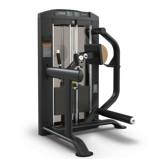
- Page 1 SPL1700 GLUTE PRESS OWNER’S MODEL SPL1700 MANUAL MAN-SPL1700 REV03...
- Page 3 IMPORTANT! All products shown are prototype. Actual product delivered may vary. Product specifi cations, features, and software are subject to change without notice. For the current owner’s manual and documents in additional languages please visit https://truefi tness.com/support/user-manuals/ IMPORTANTE! Todos los productos mostrados son prototipos. La realidad el producto suministrado puede diferir. Especifi caciones de productos, características y software están sujetas a cambios sin previo aviso.
- Page 4 You can count on TRUE Fitness for the best service in the industry, provided by a team focused on optimizing the life of your equipment.
- Page 5 Reporting Freight Claims or Parts Damage Unfortunately, sometimes materials can be damaged during shipment. If materials are damaged during shipment, please follow the guidelines below to determine the appropriate process for you to follow. Severe Damage—Obvious damage to external packaging and internal product. Please refuse the shipment and it will be returned to TRUE by the carrier.
-
Page 6: Table Of Contents
WARNING AND INTENDED USE LABELS...........................13 ASSEMBLY INSTRUCTIONS PREASSEMBLY CHECKLIST...............................15 ASSEMBLY STEPS................................17 PREVENTATIVE MAINTENANCE DAILY INSPECTION AND MAINTENANCE.........................38 WEEKLY INSPECTION AND MAINTENANCE........................38 OTHER SCHEDULED PREVENTATIVE MAINTENANCE....................39 CLEANING THE EQUIPMENT..............................39 CABLE INSPECTION AND MAINTENANCE........................40 WEIGHT STACK SELECTOR PIN INSPECTION.........................43 WARRANTY INFORMATION SPL1700 COMMERCIAL LIMITED WARRANTY........................44... -
Page 7: Safety Instructions
SAFETY INSTRUCTIONS IMPORTANT SAFETY INSTRUCTIONS—SAVE THESE INSTRUCTIONS FACILITY AND USER SAFETY PRECAUTIONS ● Review and understand all of the warning labels affi xed to this machine and on the facility safety sign. ● Be certain that the machine operation is understood before it is used. Refer to the instructional procedure label affi xed to the machine. - Page 8 INSTALLATION SAFETY PRECAUTIONS ● Read this installation manual entirely before assembling this equipment. ● Verify that there is adequate space surrounding this piece of equipment for safe access and operation. Installation must meet ADA requirements for accessibility. ● Install this piece of equipment on a solid level surface that does not deviate more than 1/8” over a 10’ distance (or as defi...
-
Page 9: General Care And Maintenance
GENERAL CARE AND MAINTENANCE IMPORTANT Preventative maintenance is crucial to maintaining the function and safety of this equipment. Your facility must establish written guidelines for preventative maintenance and keep written or online records of the maintenance performed on these products. As a minimum, the items presented in the SAFETY section of this document and the items that follow here, should be included in your maintenance program. -
Page 10: Commercial Maintenance Schedule
COMMERCIAL MAINTENANCE SCHEDULE Commercial Maintenance Schedule Daily Weekly Monthly 6 Months Annually Inspect cables for wear, tension, and proper connection if equipped. Replace at the fi rst sign of wear. Inspect cable length and cable end fi ttings. Replace at the fi rst sign of wear. Inspect all nuts and bolts and tighten if needed. -
Page 11: Dimensions And Weights
190 lbs / 87 kg 250 lbs / 114 kg 310 lbs / 141 kg LENGTH HEIGHT 57” 58” 145 cm 147 cm WIDTH 42” 107 cm SHROUD OPTIONS Shroud Options Shrouds Model Description Acrylic Metal SPL1700 Glute Press SPLSRDPS SPLSRDMS... -
Page 12: Weight Stack Configurations
Number of Bumpers Top Weight** Model Description Light (L) Standard Heavy (H) Light (L) Standard Heavy (H) Generation 1 Generation 2 SPL1700 Glute Press SPL-00- SPL-00- TPL200X TPL300X SPL-ADRWT SPL-ADRWT * One box contains four 15lb / 6.8kg weight plates. REV02... -
Page 13: Warning And Intended Use Labels
Replace all labels that may be worn, damaged, or missing. To replace any worn or missing decals contact TRUE product support (service@truefi tness.com // 800.883.8783). TRUE FITNESS TECHNOLOGY, INC 865 HOFF RD, ST LOUIS MISSOURI 63366 USA MODEL NO: SPL1700... - Page 14 WARNING AND INTENDED USE LABELS CUT OUT AREA LBL-ADJ-SPL033 LBL-ADJ-SPL035 Generation 1 Generation 2 LBL-ADJ-SPL013 LBL-QR-SPL1700 LBL-WS-SPL310 LBL-ADJ-SPL027 LBL-PR-SPL1700...
-
Page 15: Assembly Instructions
ASSEMBLY INSTRUCTIONS PREASSEMBLY CHECKLIST CAUTION: Use caution when assembling this product. Unpacking and assembling this product requires two or more people. Use caution when unpacking this product. Avoid damage to the product and product pads. DO NOT use a box cutter. DO NOT slice into the packaging. VERIFY BOX CONTENTS IMPORTANT! Please verify box contents. - Page 16 SPL17PDKT KIT, SPL1700 PADS SPL-00-CVR021 CAP, UPRIGHT SPL-00-CVR022 TRAY, UPRIGHT COVER SPL-17-ARM100X SUBASSEMBLY, SPL1700 ARM SPL-17-CBL000 SUBASSEMBLY, CABLE, UPRIGHT, SPL1700 SPLSRDPS* SHROUD SET SHORT ACRYLIC, SPL SPLSRDMS* SHROUD SET, SPL, SHORT METAL SPL-00-GRD101X GUIDE ROD ASSEMBLY 12** SPL-00-WBR002** WEIGHT STACK BUMPER...
-
Page 17: Assembly Steps
ITEM PART DESCRIPTION Allen Wrench SPL-17-MFR100X MAIN FRAME ASSEMBLY SPL-17-UPR100X UPRIGHT ASSEMBLY SPL-17-ARM100X SUBASSEMBLY, SPL1700 ARM C1255 LPSHCS, 3/8”-16 X 3/4” E-COAT C 749B LOCK WASHER, 3/8”, BLK ZP SPL-17-CAP001 D 840B C CLAMP 25.4MM SHAFT W/2 SCREW SPL-17-SPC001 SPACER... - Page 18 STEP 1—ATTACH MAIN FRAME ASSEMBLY TO UPRIGHT ASSEMBLY CONTINUED b. Align the main frame assembly with the upright assembly. Using an allen wrench, attach the main frame assembly to the upright assembly using the 6 hex screws and 6 lock washers you removed previously. NOTE: To help align parts, loosely attach all screws before fully tightening.
- Page 19 STEP 1—ATTACH MAIN FRAME ASSEMBLY TO UPRIGHT ASSEMBLY CONTINUED c. Using an allen wrench, remove the 1 hex screw, 1 lock washer, 1 bolt cap, 1 C clamp, and 1 spacer from the arm. d. Using an allen wrench, attach the arm to the upright assembly using the 1 hex screw, 1 lock washer, 1 bolt cap, 1 C clamp, and 1 spacer you removed previously.
- Page 20 SPL-17-UPR100X UPRIGHT ASSEMBLY SPL-17-MFR100X MAIN FRAME ASSEMBLY SD0183 PULLEY 114MM Wrench SPL-17-CBL000 SUBASSEMBLY, CABLE, UPRIGHT, SPL1700 C1258 LPSHCS, 3/8”-16 X 1-3/4” E-COAT C 766A LOCK NUT, 3/8”-16 X 17/64”, NYLON Socket Wrench C 754B WASHER, FLAT, 3/8” SAE, BLK C1260 LPSHCS, 3/8"-16 X 2"...
- Page 21 STEP 2—ROUTE CABLE THROUGH UPRIGHT AND MAIN FRAME ASSEMBLIES CONTINUED a. Using an allen wrench and a socket wrench or open end wrench, remove and set aside the top upright pulleys using 2 hex screws, 4 fl at washers, and 2 lock nuts. b.
- Page 22 STEP 2—ROUTE CABLE THROUGH UPRIGHT AND MAIN FRAME ASSEMBLIES CONTINUED c. Route the upright cable through the main frame and the top of the upright assembly and around the pulleys. d. Using an allen wrench and a socket wrench or open end wrench, reattach the top upright pulleys using 2 hex screws, 4 fl...
- Page 23 STEP 2—ROUTE CABLE THROUGH UPRIGHT AND MAIN FRAME ASSEMBLIES CONTINUED Attach the upright cable to the cable attachment point using the cable bolt. IMPORTANT! A minimum of 1/2" (12.7 mm) of the threaded portion of the cable bolt must be threaded into the cable attachment point.
- Page 24 SPL-00-GRD101X GUIDE ROD ASSEMBLY Cloth SPL-00-WBR002* WEIGHT STACK BUMPER SPL-00-PIN030X SUBASSEMBLY, SELECTORY PIN SPL-17-CBL000 SUBASSEMBLY, CABLE, UPRIGHT, SPL1700 Lubricant D1261 CABLE BOLT FTG, 1/2-13 X 1-3/4” C1256 LPSHCS, 3/8”-16 X 1” E-COAT C 749B LOCK WASHER, 3/8”, BLK ZP C 754B WASHER, FLAT, 3/8”...
- Page 25 STEP 3—ATTACH WEIGHT STACK TO UPRIGHT ASSEMBLY CONTINUED a. Using an allen wrench, remove and set aside the guide rod bracket from the upright assembly using 2 hex screws, 2 lock washers, and 2 fl at washers. b. Slide the 2 guide rods into place on the upright assembly.
- Page 26 STEP 3—ATTACH WEIGHT STACK TO UPRIGHT ASSEMBLY CONTINUED e. Using an allen wrench, reattach the guide rod bracket to the upright assembly using 2 hex screws, 2 lock washers, and 2 fl at washers.
- Page 27 STEP 3—ATTACH WEIGHT STACK TO UPRIGHT ASSEMBLY CONTINUED Insert the selector pin and route the upright cable down through the hole on the upright assembly. Using an open end wrench, attach the cable bolt to the top weight assembly. IMPORTANT! A minimum of 1/2" (12.7 mm) of the threaded portion of the cable bolt must be threaded into the top weight assembly.
- Page 28 STEP 3—ATTACH WEIGHT STACK TO UPRIGHT ASSEMBLY CONTINUED h. Insert the hex screw through the lock washer, fl at washer, and selector pin attachment point and reattach it to the Generation 1 top weight assembly using an allen wrench. Insert the hex screw through the lock washer, fl at washer, and selector pin attachment and reattach it to the Generation 2 top weight assembly using an allen wrench.
- Page 29 STEP 3—ATTACH WEIGHT STACK TO UPRIGHT ASSEMBLY CONTINUED After selecting the appropriate weight stack labels, peel and remove the backing from the weight stack labels. Using the selector pin retainer tube and the selector pin in the heaviest weight plate option, align the weight stack label with the plates.
- Page 30 STEP 4—ATTACH ACRYLIC SHROUDS TO UPRIGHT ASSEMBLY NOTE: Supplemental acrylic shroud video available on vimeo.com: https://vimeo.com/723539522?share=copy. NOTE: Supplemental metal shroud video available on vimeo.com: https://vimeo.com/774417897?share=copy. TOOLS NEEDED ITEM PART DESCRIPTION Allen Wrench SPL-17-UPR100X UPRIGHT ASSEMBLY SPLSRDPS* SHROUD SET SHORT ACRYLIC, SPL SPLSRDMS* SHROUD SET, SPL, SHORT METAL Flat Head Screwdriver...
- Page 31 STEP 4—ATTACH ACRYLIC SHROUDS TO UPRIGHT ASSEMBLY CONTINUED b. Assemble the acrylic front shrouds and insert them into the upright assembly using a rubber mallet. c. Using an allen wrench and a socket wrench or open end wrench, insert and tighten the 4 hex screws and 4 lock nuts into the front shrouds.
- Page 32 STEP 4—ATTACH METAL SHROUDS TO UPRIGHT ASSEMBLY a. Using an allen wrench, socket wrench or open end wrench, and a fl at head screwdriver, remove and set aside the shroud fasteners from the upright assembly using 4 hex screws, 4 lock nuts, 2 twist lock screws, and 2 lock washers.
- Page 33 STEP 4—ATTACH METAL SHROUDS TO UPRIGHT ASSEMBLY CONTINUED b. Slide the front metal shrouds onto the upright assembly. c. Using an allen wrench and a socket wrench or open end wrench, secure the front shrouds to the upright assembly using the 4 hex screws and 4 lock nuts. d.
- Page 34 STEP 5—ATTACH TOP COVER TO UPRIGHT ASSEMBLY NOTE: Supplemental top cover video available on vimeo.com: https://vimeo.com/723539522?share=copy. TOOLS NEEDED ITEM PART DESCRIPTION Allen Wrenches SPL-17-UPR100X UPRIGHT ASSEMBLY 3/32" and 5/32" SPL-00-CVR021 CAP, UPRIGHT SPL-00-CVR022 TRAY, UPRIGHT COVER SPL-00-CVR023 MAT, UPRIGHT TRAY C1239 FHCS, 8-32 X 1/2”...
- Page 35 STEP 5—ATTACH TOP COVER TO UPRIGHT ASSEMBLY CONTINUED e. Reattach the tray cover onto the top cover using the Fully press the tray mat onto the tray cover. 4 previously set aside the tray cover hex screws. top cover Verify that the tray mat is fully pressed into the tray cover.
- Page 36 STEP 6—ATTACH PHONE HOLDER TO UPRIGHT ASSEMBLY TOOL NEEDED ITEM PART DESCRIPTION #2 Phillips Screwdriver SPL-17-UPR100X UPRIGHT ASSEMBLY SPL-00-RCK001 HOLDER, PHONE C1226 PHCS, #10-32 X 1”, BLK Using a #2 Phillips screwdriver, attach the phone holder to the upright assembly using 2 screws.
- Page 37 ITEM PART DESCRIPTION Allen Wrench SPL-17-MFR100X MAIN FRAME ASSEMBLY SPL17PDKT KIT, SPL1700 PADS C1257 LPSHCS, 3/8”-16 X 1-1/4” E-COAT C 749B LOCK WASHER, 3/8”, BLK ZP C 754B WASHER, FLAT, 3/8” SAE, BLK Using an allen wrench, attach the chest pad to the main frame assembly using 2 hex screws, 2 lock washers, and 2 fl at washers.
-
Page 38: Preventative Maintenance
PREVENTATIVE MAINTENANCE Preventative maintenance is crucial to maintaining the function and safety of this equipment. Your facility must establish written guidelines for preventative maintenance and keep written or online records of the maintenance performed on these products. As a minimum, the items presented in the Safety Instructions section of this document and the items that follow here, should be included in your maintenance program. -
Page 39: Other Scheduled Preventative Maintenance
OTHER SCHEDULED PREVENTATIVE MAINTENANCE TRUE recommends that scheduled maintenance be performed by a qualifi ed service technician. Please contact your dealer or visit www.truefi tness.com to contact a local TRUE authorized service technician. Monthly Clean guide rods and lubricate with a Tefl on grease if equipped with guide rods. Every 6 Months Lubricate pivot bearing and linear bearings with lithium grease. -
Page 40: Cable Inspection And Maintenance
CABLE INSPECTION AND MAINTENANCE One of the most critical areas that require frequent inspection on any weight machine is the cable or belt system that lifts the weight stack if the machine is equipped with those items. Sudden failure of a worn cable can, in some instances, result in injury to the user. - Page 41 CABLE TENSION (IF APPLICABLE) Ensure that the cables are adjusted to remove any slack using the threaded end fi ttings. These are normally located at the weight stack connection. Depending upon the machine, there may be multiple threaded fi tting on multiple cables. You can determine if there is too much slack by performing the exercise.
- Page 42 CABLE FITTING ATTACHMENTS (IF APPLICABLE) Depending upon the machine, cable end fi ttings can either be securely fi xed, rotate about a single axis, or can be free fl oating. On machines where the cable fi tting is designed to rotate about a single axis, verify that the fi tting rotates freely and that the hardware used to secure the cable pivot axle (most likely a pin or a bolt) is correctly fastened.
-
Page 43: Weight Stack Selector Pin Inspection
WEIGHT STACK SELECTOR PIN INSPECTION Verify that the weight stack selector pin is attached with the coiled lanyard to the top plate (if equipped). Verify the selector pin slides in and out of each weight plate. Place the selector pin in the top plate. Cycle the machine through the intended motion. -
Page 44: Warranty Information
WARRANTY INFORMATION SPL1700 LIMITED WARRANTY SAVE TIME AND REGISTER ONLINE! https://truefi tness.com/support/warranty-registration/ All TRUE® Fitness products are distributed by TRUE FRAME and are warranted to the original registered product *This limited warranty on the structural frame does not purchaser and the parts of the TRUE product (the include paint or coatings. - Page 45 SAVE TIME AND REGISTER ONLINE! https://truefi tness.com/support/warranty-registration/ THE TRUE LIMITED WARRANTY IS SUBJECT TO AND WILL BE IN ACCORDANCE WITH THE CONDITIONS SET FORTH BELOW: This limited warranty is valid for the United States and 13. This limited warranty does not cover damage or equipment Canada only.
- Page 46 IMPORTANT! Failure to register this product will result in no servicing or authorization of parts to be shipped. To mail your warranty information, please fi ll in the information below and mail to: Service Dept., TRUE Fitness, 865 Hoff Road, St. Louis, MO 63366 (or save postage and register online at www.truefi tness.com).
- Page 48 1.800.883.8783 865 Hoff Road St. Louis, MO 63366 T R U E F I T N E S S . C O M MAN-SPL1700 Owner’s Manual, Assembly Guide, and Warranty Card REV03 © 2024 TRUE Fitness All Rights Reserved...
Need help?
Do you have a question about the SPL1700 and is the answer not in the manual?
Questions and answers