Table of Contents
Advertisement
Quick Links
Advertisement
Table of Contents

Subscribe to Our Youtube Channel
Related Manuals for Siqura S620 E


Summary of Contents for Siqura S620 E
- Page 1 S620 E Firmware Version 4.22 Dual H.264/MPEG-4 video encoder...
- Page 2 Any brand names mentioned in this manual are registered trademarks of their respective owners. Liability Siqura accepts no liability for claims from third parties arising from improper use other than that stated in this manual. Although considerable care has been taken to ensure a correct and suitably comprehensive description of all relevant product components, this manual may nonetheless contain errors and inaccuracies.
-
Page 3: Table Of Contents
Contents About this manual ..................Safety and compliance ................Safety ....................Compliance ..................Product overview ..................Features ..................... Models ....................Description ..................Front panel ..................Install the unit ..................Power the unit ..................Connect cables ..................Startup ....................Connector pin assignments ..............Update device definitions .............. - Page 4 Contents 10.2 View live video ..................10.3 Use your browser for PTZ control ............Status ....................... 11.1 View status information ................ 11.1.1 Stream states ................. 11.1.2 Edge recording ................11.2 View measurements data ..............11.2.1 General, network, and stream measurements ........11.2.2 SD card size ..................
- Page 5 Contents 13.7.4 Graphics ..................13.7.4.1 Advanced ................. 13.8 VMD ....................13.8.1 VMD startup ..................13.8.2 Configure detection parameters ............13.8.3 Set the mask .................. 13.8.4 VMD detection window ..............13.8.5 VMD alarm ..................13.8.6 Advanced ..................13.9 FTP Push .................... 13.9.1 Post JPEG images ................
- Page 6 Contents 15.5 Advanced ................... 15.5.1 RS-4xx Settings ................15.5.2 Transmitter # ................. 15.5.3 Receiver 1 ..................Data RS-232 ....................16.1 Configure RS-232 settings ..............CC Streams ....................17.1 CC channels, CC status, and alarms ............17.2 Input # Settings .................. 17.3 Make contact closure connections ............
- Page 7 22.3.4 SNMP Traps ..................22.3.5 Polling .................... 22.4 MX ..................... 22.4.1 MX/IP ..................... 22.4.2 MX Notifications ................22.5 Auto Discovery ..................22.5.1 Advertise the S620 E ................ 22.5.1.1 Note ..................22.6 ONVIF ....................22.6.1 Note ....................22.7 FTP/Telnet ..................22.8 Firmware ....................
-
Page 8: About This Manual
This manual is intended for installers and users of the S620 E. What you should already know To be able to install and use the S620 E properly, you should have adequate knowledge and skills in the following fields. ●... -
Page 9: Safety And Compliance
Failure to comply with any precaution, warning, or instruction noted in the manual is in violation of the standards of design, manufacture, and intended use of the module. Siqura assumes no liability for the customer's failure to comply with any of these safety requirements. - Page 10 Optical safety The following optical safety information applies to S620 E models with SFP interface. This product complies with 21 CFR 1040.10 and 1040.11 except for deviations pursuant to Laser Notice No. 50, dated June 24, 2007. This optical equipment contains Class 1M lasers or LEDs and has been designed and tested to meet IEC 60825-1:1993+A1+A2 and IEC 60825-2:2004 safety class 1M requirements.
-
Page 11: Compliance
Safety and compliance To ensure EMC compliance of the equipment, use shielded cables for all signal cables including Ethernet, such as CAT5E SF/UTP or better, as defined in ISO IEC 11801. For power cables, unshielded three wire cable (2p + PE) is acceptable Ensure that all electrically connected components are carefully earthed and protected against surges (high voltage transients caused by switching or lightning). -
Page 12: Product Overview
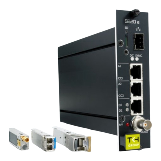
S620 E /SA Stand-alone version of rack-mount models Rack-mount S620 E units are designed to be slotted into MC 10 or MC 11 power supply cabinets. Front panel LEDs indicate network status, stream status (sync), and DC power. All models have backup battery power for their clocks. -
Page 13: Description
Quad streaming The S620 E is capable of streaming 2x H.264 at full frame rate. It can also stream 2x MPEG-4 or MJPEG simultaneously. Each stream is optimised for its purpose: high-quality H.264 for live viewing, low-bandwidth MPEG-4 for storage, or easy-to-decode MJPEG for web applications and remote devices. -
Page 14: Front Panel
Product overview FTP push Upon an event, the S620 E can push a JPG image to one or two FTP servers. The event can be triggered externally by VMD, the Image Monitor, or Tamper Detect. The S620 E can also periodically upload images to the remote server(s). - Page 15 RS-232 0/1 data input Ethernet green/yellow Green on/off: 100/10 socket LEDs Mbit Yellow on/blink: link OK, active Yellow off/flash: link down, TX attempt S620 E front panel features and indications Pin assignments are given in section Connector Pin Assignments.
-
Page 16: Install The Unit
Install the unit This chapter describes how to install your S620 E unit and connect power, network, and signal cables. In This Chapter 4.1 Power the unit...................... 16 4.2 Connect cables..................... 16 4.3 Startup........................17 4.4 Connector pin assignments..................17 4.5 Update device definitions..................18... -
Page 17: Startup
Install the unit Important: Through-connecting the signal ground lines of RS-data interfaces is mandatory, as is proper grounding. See also the section on pin assignments later in this chapter. Startup After startup, the DC LED will light and the network indicator lights go through an on/off sequence. -
Page 18: Update Device Definitions
Ethernet connector socket pinning Update device definitions If the S620 E is not supported by the TKH Security application software on your host PC you can download EMX updates and MX Plug-in updates at www.tkhsecurity.com/support-files. Install the EMX update first if you are performing both update types. -
Page 19: Connect The Unit
The webpages of the S620 E provide a convenient way of accessing its settings. You can log on to the web interface of the S620 E from a PC which is on the same subnet as the unit. Follow the steps below to open communication with the S620 E and configure its network settings. - Page 20 In the Internet Protocol Version 4 (TCP/IPv4) Properties dialog box, click Use the following IP address. Enter an IP address which assigns your PC to the same subnet as the S620 E - that is, within the 10.x.x.x range. Use 255.0.0.0 as a subnet mask.
-
Page 21: Establish Video And Other Signal Connections
Interfaces chapter. An alternative, convenient method to establish video, audio, data, and contact closure (I/O contacts) connections is to use the webpages of the S620 E. For detailed information, see the chapters which describe these pages. Separate application software, such as MX Configuration Tool, can be used as well. -
Page 22: Port Numbers
Connect the unit General procedure for making links In both connection methods mentioned above, perform the following steps to make a unicast one-way link (video, audio, data, contact closure) from source to destination. ● In the transmitter, specify a destination IP address and a destination port number. ●... -
Page 23: Interfaces
Web UI Using the S620 E's web server is the most straightforward way to access the unit. The webpages enable you to configure the settings of the S620 E and view live video images from a standard web browser. -
Page 24: Mx/Ip
For more information, refer to appropriate literature on SNMP. The S620 E supports in-band SNMP. Via SNMP, several status variables can be read and traps can be generated on events. You can configure S620 E SNMP settings on the SNMP tab of the Device Management page. - Page 25 The S620 E supports all the mandatory parts and some of the optional parts of the NTCIP CCTV specification as laid down in the NTCIP 1205:2001 v01.08 document. For details about the NTCIP configuration of the S620 E, see Appendix: NTCIP Configuration.
-
Page 26: Stream Media Via Rtsp
Stream media via RTSP The easiest way to extract a video or audio stream from the S620 E is to use the Real-Time Streaming Protocol (RTSP). This chapter explains the role of the S620 E in RTSP media sessions and describes how to open a media stream from the unit in a video player plug-in. -
Page 27: Transfer Via Udp Or Tcp
TCP/IP (RTP, RTP over RTSP, RTP over RTSP over HTTP) The S620 E reports to the client that it supports transfer over UDP and TCP. The choice is made on the client side. In VLC, for example, using a TCP connection can be forced (Preferences >... -
Page 28: Access The Webpages
To connect to the unit via your web browser Open your web browser. Type the IP address of the S620 E in the address bar, and then press ENTER. If your network configuration is correct you are directed to the login page of the unit. -
Page 29: Find The Unit With Device Manager
Use the Filter box, to search for a specific series or model. To connect to the webpages of the S620 E, double-click its entry in the device list, - or - Right-click the entry, and then click Open Web Page. -
Page 30: Connect Via Upnp
Access the webpages Connect via UPnP Universal Plug and Play (UPnP) support is enabled by default on the S620 E. With the UPnP service enabled in Windows (see Appendix: Enable UPnP in Windows), you can access the unit from Windows Explorer. - Page 31 Connect dialogue box Note: The appearance of the S620 E webpages and dialogue boxes is determined by the operating system and web browser used on the host PC. Therefore, some of the screenshots in this manual may slightly differ from what you actually see on your screen.
-
Page 32: Navigate The Webpages
S620 E menus available to (from left to right) Admin, Operator, and Viewer accounts Access control Whether a specific S620 E webpage is available to you on the navigation menu depends on the user account you logged in with. The unit supports three account types with associated... -
Page 33: Webpage Elements
Important: Be aware that section with additional settings. configuring Advanced Settings requires in-depth understanding of the impact of your changes on the Closes the Advanced Settings workings of your S620 E. If in section. doubt, do not change the default values. -
Page 34: View Live Video Via Browser
On the Live Video page, you can view live video from a video source which is connected to the S620 E. From this page, you can also control a connected PTZ camera if the camera supports the PTZ driver selected on the PTZ page of the S620 E. -
Page 35: View Live Video
View live video via browser 10.2 View live video Live View activated With Live View enabled, the Live Video page has the following items. Item Description <<Stop Live View Closes the preview. Encoder Encoder 1 The video encoder used to encode the images seen in the preview. -
Page 36: Use Your Browser For Ptz Control
PTZ drivers not included in the driver list on the PTZ page can be uploaded to the S620 E via PTZ Driver Management on the same page. - Page 37 View live video via browser PTZ Control panel Preset Use the Preset section to define and recall preset camera positions. To enter and save a preset camera position Click the appropriate number button(s) to enter the preset number. Adjust the position of the camera for the desired view. When satisfied with the position, click SET.
-
Page 38: Status
Status The status information and measurements on the Status page may provide helpful clues to identify and troubleshoot technical issues. In This Chapter 11.1 View status information..................38 11.2 View measurements data..................40 11.1 View status information Status page: a snapshot with automatic page updating 11.1.1 Stream states The Status tab provides information on the stream states of video and audio streams. -
Page 39: Edge Recording
Status Stream state Description There is nothing wrong with the stream. Note that if the video signal is removed from the video input on the encoder side, the Decoder rx state is still reported as OK, since the video transmitter is sending a stream - that is, a No Video image - to the decoder. -
Page 40: View Measurements Data
Status 11.2 View measurements data Status > Measurements 11.2.1 General, network, and stream measurements The Measurements tab shows general measurements, such as the module temperatures (current and peak) and the module uptime. You also find network specifics here, such as the MAC address, the actual IP address, the network load from this module, the load information per processor, and signal stream-specific details. -
Page 41: Ftp Push
Status 11.2.3 FTP Push You can use the FTP Push data to monitor the FTP Push process. -
Page 42: Network
In the Network Settings section, you can set the name of the unit, the IP address, the subnet mask, and the gateway IP address. For correct functioning of the S620 E, it is vital to set its network addressing to be compatible with the subnet it is hooked into. -
Page 43: Advanced
Services Item Description RTSP server Select this check box to enable the S620 E to act as a server in RTSP enable media sessions. RTSP server port This is the port number used to contact the RTSP server. The default transport layer port number for the RTSP protocol is 554 for both UDP and TCP transports. -
Page 44: Video
Video On the Video page, you can configure settings for video encoding, on-screen display, video motion detection, FTP push, image quality, tamper detect, and privacy masks. In This Chapter 13.1 Video encoding overview..................44 13.2 General......................45 13.3 Encoder 1......................48 13.4 H.264 - 1...................... -
Page 45: General
Up to twenty streams can be retrieved using RTSP. A total of twelve copies – three per independent MPEG-4, MJPEG, or H.264 video stream – can be transmitted to different unicast and/or multicast destinations using TKH Security's proprietary MX protocol. The S620 E supports source-specific multicast (SSM) and it is also possible to use the Session Announcement Protocol (SAP) to transmit MPEG-4/MJPEG and H.264 streams to multicast... -
Page 46: Video Settings
Video 13.2.1 Video Settings Item Description PAL / NTSC Auto, PAL, or NTSC. The video display standard. Video source Interlaced Interlaced scan, originating from traditional television systems, uses two fields to create a frame, one holding the odd lines in the image, the other holding the even ones. -
Page 47: Encoder Priorities
Video Item Description Sharpness Default Restores the original values. 13.2.2 Encoder Priorities Priority list Using the Encoder Priorities list, you can assign a priority to Encoders 1 and 2, and the Live View encoder. H.264 encoding uses a dedicated digital chip and is therefore not included in the list. -
Page 48: Encoder 1
Video 13.3 Encoder 1 Video > Encoder 1... -
Page 49: Encoder Settings
Encoding mode MPEG-4 or MJPEG The method used to compress the analog video input signal. The S620 E can stream (M)JPEG over UDP and HTTP. ● To enable and configure UDP/MJPEG streaming, select MJPEG from the Encoding mode list and configure settings. - Page 50 For more information about CIF resolutions, see "Notes" later in this chapter. Note: The S620 E will simultaneously handle dual H.264 encoding and dual MPEG-4/MJPEG encoding at full frame rate, and Live View encoding at 5 frames per second. Setting Encoders 1 and 2 to perform MPEG-4/MJPEG encoding in D1 resolution at the same time may overtax the hardware.
-
Page 51: Combinations Of Settings
Video Item Description Mute Select/clear this box to mute/unmute audio. 13.3.2 Combinations of settings Set sensible combinations of video bit rate mode, resolution, GOP length, and frame and bit rates. When setting and saving these values, you may notice that inappropriate value combinations are ‘corrected’... - Page 52 Video In the MX Transmitter Settings section, specify the destination IP address. This is the address of the video decoder which will receive the video stream. Enter the port number of the decoder. For more information about port numbers, see the Port Numbers section. Select Enable, and then click Save.
-
Page 53: Advanced
Video 13.3.5 Advanced Important: If in doubt about these settings, do not change the default values. 13.3.5.1 Encoder Depending on the selected encoding mode, specific parameter values in this section are dimmed - that is, not available for configuration. MPEG-4 mode Video >... - Page 54 Video Item Description VBR maximum Range: [0...15000]. Sets a limit for variable bit rate. bit rate Q min I Used to achieve consistent picture quality within a single GOP or across consecutive GOPs. Lower values produce a better picture, but will yield Q min P higher bit rates and require more processing.
-
Page 55: Stream Manager
Video Item Description VBR maximum bit Range: [0...15000]. Sets a limit for variable bit rate. rate Frame rate divider Relates to the frame rate configured in the Encoder Settings section. X-resolution Variables that enable you to freely set picture resolution instead of using the resolution presets in the Encoder Settings section. -
Page 56: Transmitter
Video Note on Low Latency mode: This mode may cause packet loss in the network. In this mode, short bursts of 100 MB data may overflow the input buffer of an Ethernet aggregation switch. As a rule of thumb, the average load of an Ethernet port should not exceed 40% of its maximum load (i.e. -
Page 57: Rtsp Transmitter
Video Item Description DSCP field Range: [0...63]. DSCP (Differentiated Services Code Point) uses the first 6 bits of the ToS (Type of Service) field in the header of IP packets for packet classification purposes. The bit pattern in the field indicates the type of service and forwarding behavior at the next node. -
Page 58: Sap Settings
SAP announcer The S620 E includes a SAP announcer. The Session Announcement Protocol is used to advertise that a media stream generated by the S620 E is available at a specific multicast address and port. The S620 E can send SAP multicast streams for its H.264, MPEG-4, and audio encoders. The video streams include audio if audio is enabled on the Audio webpage and if the multicast IP range is the same as for video. - Page 59 Video Item Description Enable SAP When selected, session announcements are sent at the frequency determined by the Announcement interval parameter and the media stream is transmitted to the multicast IP address specified in the Stream dest. IP address box. Stream name Enter a descriptive name to identify the media stream.
-
Page 60: Meta Data Insertion
Meta data insertion Enabling All S620 E encoders can be configured to include meta data in the video streams they generate. The insertion of meta data is enabled by setting an interval via the Advanced Settings of the encoder. A meta data message is added to the stream as a block of data with a fixed format (see examples below). - Page 61 Video 0x00 0x00 0x01 0xB2 User data message For MJPEG, these (for the rest identical) messages are inserted as comment field (FF FE): Size 0xFF 0xFE Size (LSB) User data message (MSB) For H.264, these (for the rest identical) messages are inserted as SEI NAL-unit (0x06), marked as type User Data Unregistered (0x05): 0x06 0x05...
- Page 62 Video Status 2 General status Bit 0 Reserved for Temperature alarm Bit 1 (for future use, will be ‘0’) Bit 2 (for future use, will be ‘0’) Bit 3 (for future use, will be ‘0’) Bit 4 (for future use, will be ‘0’) Bit 5 Reserved for Audio present Bit 6...
-
Page 63: Notes
Video 13.3.5.7 Notes Note on Differentiated Services: Differentiated Services (DiffServ, or DS) is a method for adding QoS (Quality of Service) to IP networks. In routed networks, critical network traffic such as video and audio streams, which require a relatively uninterrupted flow of data, can get blocked due to other traffic. - Page 64 Video Stream Manager and FloodGuard...
-
Page 65: H.264 - 1
Video 13.4 H.264 - 1 Video > H.264 - 1... -
Page 66: Encoder Settings
VGA (640x480) and QVGA (320x240) are also supported. For more information on CIF resolutions, see below. Note: The S620 E will simultaneously handle dual H.264 encoding and dual MPEG-4 encoding at full frame rate, and Live View encoding at 5 frames per second. -
Page 67: Constant Quality Mode Configuration
Video Item Description Quality Constant quality mode Reflects the amount of compression. Generally only speaking: the higher the quality setting, the lower the compression ratio and the more bits are consumed. This means a trade-off has to be found between the desired quality level and available bandwidth. -
Page 68: Profiles
Video 13.4.3 Profiles To facilitate the configuration of H.264 encoding settings, the Profile list offers a number of profiles - that is, combinations of settings for specific purposes. H.264 Profile list The following table lists parameter settings for each profile. - Page 69 Video Profile Settings H.264 - High quality - Camera (4.0M Max bit rate: n/a CBR) Bit rate: 4000 kbit/s Mode: Constant bit rate Quality: n/a Resolution: D1 GOP: 25 Frame rate divider: 1 Stream bandwidth limit: 20000 kbit/s H.264 - Low bit rate - Camera (1.0M Max bit rate: n/a CBR) Bit rate: 1000 kbit/s...
-
Page 70: Parameter Value Combinations
Video 13.4.4 Parameter value combinations Set sensible combinations of video bit rate mode, resolution, GOP length, and frame and bit rates. When you set and save these values, inappropriate value combinations are 'corrected' by automatic selection of the closest suitable combination. Important: If in doubt about the effects of specific encoder settings, you are advised to select the profile offering the closest match to your required application. -
Page 71: Encoder
Video 13.4.6.1 Encoder Video > H.264 > Advanced > Encoder... - Page 72 Video Item Description CQM max bit Available in Constant quality mode (CQM). Use this setting to set the rate maximum bit rate for a given picture quality configured in the Encoder Settings section. Frame rate Relates to the frame rate configured in the Encoder Settings section. divider X-resolution Variables that enable you to freely set picture resolution instead of using...
-
Page 73: Stream Manager, Transmitter #, Rtsp Transmitter, And Sap
Video 13.4.6.2 Stream Manager, Transmitter #, RTSP Transmitter, and SAP Configuring Stream Manager, Transmitter #, RTSP Transmitter, and SAP settings for H.264 encoding is done in the same way as for Encoders 1 and 2. For more information, see the description of the Advanced Settings for these encoders. -
Page 74: Live View
Video > Live View 13.6.1 (M)JPEG output The S620 E provides multiple (M)JPEG output methods. ● To transport JPEG over HTTP and/or to use the Live View previews in the webpages, enable the Live View encoder and configure its settings. -
Page 75: Encoder Settings
Set sensible combinations of mode, resolution, frame rate and (maximum) bit rate. It is advised to limit MJPEG encoding to 5 fps Frame rate when the S620 E is also handling MPEG-4 encoding with 1xD1 and (Maximum) bit 1xCIF or 2CIF at full frame rate. -
Page 76: Osd
Video > OSD 13.7.1 OSD facilities The S620 E features programmable on-screen display (OSD) facilities. One graphic and up to three OSD text bars can be displayed, each of which can be independently configured. Visual feedback is provided in the preview. -
Page 77: Text Settings
Video 13.7.2 Text Settings Item Description Enable All OSD objects can be enabled and configured separately. To (temporarily) remove a bar or graphic from the screen, clear the Enable check box. OSD text The text to be displayed. Maximum: 255 characters. Text is displayed in a single line. -
Page 78: Advanced
Video Item Description Text color Changes made here and in the other fields are immediately written into the device and reflected in the preview. Border/outline color Font size Range: [0...256]. Predefined positions Presets for positioning the OSD object. Transparency Move the slider or type a percentage. X Position Variables that enable you to freely position the object, instead of using the presets. -
Page 79: Graphics
Video Video > OSD > Text 1 > Advanced > Font Management To upload a font In the Font management section, click Browse. The Open dialog box displays. Browse to the folder containing the font to be uploaded. Select the correct file (.ttf extension), and then click Open. The file appears in the File text box on the web page. -
Page 80: Advanced
Video > OSD > Graphics > Advanced > Graphic Management You can upload your own graphics with a maximum file size of 100 kB to the S620 E. If necessary, use a picture resize tool to reduce the file size. -
Page 81: Vmd
Video Browse to the folder containing the graphic to be uploaded. Select a file with the correct file extension (.bmp, .gif, .jpg, jpeg), and then click Open. The file appears in the File textbox. To start the upload, click Add. The graphic is added to the graphics list and to the Graphic drop-down list in the Text section. -
Page 82: Configure Detection Parameters
Video 13.8.2 Configure detection parameters Video > VMD > Configuration VMD enabled: Configuration section with controls, video picture, and motion detection inset, the latter with mask applied. The mask permits motion detection in the right half of the picture only, at the top of the stairs, so passers-by and cars would not be registered by the detector facility;... - Page 83 Video ● Hold the standard mouse button and drag, to 'brush' (i.e. mask) larger areas, with a 'Normal', 'Small', or 'Large' brush. ● Use the 'Invert Mask' button to reverse a selection. ● Hold the right mouse button and drag, to erase mask areas. ●...
-
Page 84: Vmd Detection Window
Video 13.8.4 VMD detection window The VMD detection window shows up as a small picture within the larger picture. Depending on the thresholds set, the motion detection bar on the right side of the picture shows up green or red (see figures below), the latter indicating a VMD alarm will be generated. In the pictures, the upper and lower thresholds are shown as two white markers. - Page 85 Video Item Description Frame rate divider Range: [1...100]. Used to determine the number of frames used for VMD. Only 1 divided by this value frames are evaluated. Delay Range: [1...10] frames. The delay in frames between the currently processed frame and the stored frame with which it is to be compared.
-
Page 86: Ftp Push
Video VMD Alarm: Event window high/low mark X = Event window size Y = Event window high mark Z = Event window low mark VMD alarm becomes active when in at least Y out of X frames motion is detected. VMD alarm becomes inactive when in at least Z out of X frames no motion is detected. -
Page 87: Post Jpeg Images
State>.jpg 13.9.3 FTP server A target FTP server must hold a user account associated with the S620 E. You can assign a primary server and a secondary server. Images are posted simultaneously to both the primary server and secondary server. -
Page 88: Event Management
Video Video > FTP Push > Primary Server, example settings Item Description Enable Select or clear to respectively enable/disable the connection with this server. IP address IP address of the FTP server. Port The FTP protocol typically uses port 21 on the FTP server to listen for clients initiating a connection. -
Page 89: Monitor And Troubleshoot Ftp Push
Video 13.9.5 Monitor and troubleshoot FTP Push You can monitor FTP push on the Measurements tab of the Status page. Measurements on this tab are continuously updated. In the FTP Push section, you can compare the number of incoming triggers with the number of succeeded posts. Status >... -
Page 90: Image Monitor
Video 13.10 Image Monitor Video > Image Monitor 13.10.1 Image quality check The Image Monitor can detect if images produced by the camera are still usable. It can give an indication of the performance of the camera and show whether or not it needs attention. A quality check is made against what is normally a good picture. - Page 91 Video To enable all measurements simultaneously ● In the Measurements section, click IMAGE MONITOR DISABLED. The four dials are activated, the pointers indicating the current measurements. Image Monitor: all measurements enabled To enable/disable individual measurements In the VCA Settings section, click the accordion style menu labelled with the measurement you require.
-
Page 92: Dial Legend
Video 13.10.3 Dial legend The coloured dials in the Measurements section provide a quick and easy glance at the health of the camera. You can fine-tune each measurement's alarm thresholds to your needs in the VCA Settings section. Dial legend Error state. - Page 93 TKH Security's Open Streaming Architecture (OSA) - that is, the "SPI API". The S620 E includes SNMP support for its image monitor and tampering detection. A trap is sent when bad image quality or camera tampering has been detected and another one when the situation returns to normal.
-
Page 94: Measurements Configuration
Video 13.10.4 Measurements configuration Video > Image Monitor > VCA Settings The default Measurements values will mostly work well for you. If you do need to modify them you can do so in the VCA Settings section. Item Description Configure Alarms Min. -
Page 95: Region Of Interest (Roi)
Video To configure a measurement In the VCA Settings section, click the button for the measurement you wish to configure. The measurement's settings display. Select the Enable box, if necessary. Set the alarm threshold to your requirements. Note that you can set two thresholds for Exposure (under- and overexposure) and Contrast (low and high contrast). -
Page 96: Tamper Detect
Video To delete a mask ● Press the Clear button. Item Description Brush Normal Allows grid elements to be accessed in 4- element groups. Large Allows grid elements to be accessed in 16- element groups. Small Allows grid elements to be accessed one at a time. -
Page 97: Camera Movement And Scene Changes
Video 13.11.1 Camera movement and scene changes As a result of tampering, or more accidentally, after cleaning, a camera may no longer cover the area designated for monitoring. The Tamper Detect function can detect camera position changes and scene changes such as a blocked camera view, for example. It does so by comparing the current image to one or more reference images that were captured and stored earlier. -
Page 98: Mask The Roi
Video Enter a descriptive name in the Label box. Enter a value (in seconds) for the Sampling duration. This parameter enables you to capture the background of a scene only and have specific elements such as moving objects filtered out of the image. With a longer time span for the sampling duration, persons passing in front of the camera, for example, or cars driving on a highway can be smoothed out to prevent them from triggering a changed scene alarm. -
Page 99: Delete A Reference Image
Video Current image matches Reference 1 Reference image(s) available. No match found with current image, though. The drop-down list in the Feedback View section can be used to display the current image, the best matching reference image, or a specific reference image. Feedback view list 13.11.3.4 Delete a reference image... -
Page 100: Position Measurement
Video 13.11.4 Position measurement Video > Tamper Detect > Position Measurement After creating one or more reference images you can configure the Position Measurement settings to define thresholds for allowed camera movement and image matching. Item Description Enable Enables Tamper Detect functionality. Match threshold The current image and the reference image it is compared with are considered a match upon reaching the degree of similarity specified... -
Page 101: Alarms
TKH Security's Open Streaming Architecture (OSA) - that is, the "SPI API". The S620 E includes SNMP support for its image monitor and tamper detect functions. A trap is sent when bad image quality or camera tampering has been detected and another one when the situation returns to normal. -
Page 102: Alarm Examples
Video 13.11.5.1 Alarm examples Original camera position Camera has moved to the right. Although the current image still matches Reference 1, the changed camera position results in a position alarm. Camera has moved further to the right. Blocked scene alarm Current image no longer matches any reference image, resulting in a changed scene alarm. -
Page 103: Privacy Mask
Video 13.12 Privacy Mask Video > Privacy Mask The privacy mask function aims to avoid intrusive monitoring. The S620 E supports up to 10 masks. To create a privacy mask On the Video page, click the Privacy Mask tab. Under the preview, click New. -
Page 104: Audio
Audio This chapter describes the functionality and settings found on the Audio page of the S620 E. In This Chapter 14.1 Enable audio.....................104 14.2 Make audio connections..................106 14.3 Advanced......................107 14.1 Enable audio Audio page Using the Enable check box at the top of the Audio page, you can enable/disable the entire audio functionality (the latter, for example, to prevent unwanted eavesdropping). -
Page 105: Input Settings
Audio 14.1.1 Input Settings Item Description Input select Line, Microphone, or Microphone + bias. Input Can be set to High-Z or 600 ohms, to match audio source. termination Mute Audio on/off. Enable AGC To adjust the gain to an appropriate level, Automatic Gain Control reduces the volume if the signal is strong and raises it when it is weaker. -
Page 106: Make Audio Connections
Two-way audio The figure above shows the setup for two-way audio on the side of the S620 E. The device on the other side of the connection (with the IP address 172.22.250.131) would need similar settings, that is - it must hold the IP address of the S620 E as the destination and source. -
Page 107: Mx Receiver Settings
Select/Clear to enable/disable the stream reception, respectively. Source address IP address of the codec that will transmit the stream. Port The local port number of the S620 E. 14.3 Advanced Important: If in doubt about these settings, do not change the default values. -
Page 108: Audio Output
Audio 14.3.2 Audio Output Audio > Advanced > Audio Output Item Description Bass Range: [0…18] dB. Treble Range: [0…6] dB. 14.3.3 Audio Encoder Audio > Advanced > Audio Encoder Item Description Audio format PCM 16bit, A-law 8bit, μ-law 8bit. 14.3.4 Audio Decoder Audio >... -
Page 109: Transmitter
Audio Item Description Channels Range: [1-2]. Default: 1. When selecting 1 channel, the incoming audio stream is sent to both the ‘A1’ and ‘A2’ outputs. Sample rate Range: [7850…48000]. Examples (for 1 and 2 channels): ● 7850 Hz A-law A-law ●... -
Page 110: Receiver 1
Audio Item Description DSCP field Range: [0...63]. DSCP (Differentiated Services Code Point) uses the first 6 bits of the ToS (Type of Service) field in the header of IP packets for packet classification purposes. The bit pattern in the field indicates the type of service and forwarding behavior at the next node. -
Page 111: Rtsp Transmitter
Audio Item Description Filter on source Can be used to filter incoming signals. With multiple signals sent to the port same IP address and destination port number, Filter on source port can be used to filter the input, i.e. to accept only signals from the transmitting port specified here. -
Page 112: Sap Settings
Audio Item Description DSCP field Range: [0...63]. DSCP (Differentiated Services Code Point) uses the first 6 bits of the ToS (Type of Service) field in the header of IP packets for packet classification purposes. The bit pattern in the field indicates the type of service and forwarding behavior at the next node. - Page 113 The S620 E includes a SAP announcer. The Session Announcement Protocol is used to advertise that a media stream generated by the S620 E is available at a specific multicast address and port. For more information about SAP, see the note below.
-
Page 114: Data Rs-422/485
Data RS-422/485 This chapter describes the Data RS-422/485 page of the S620 E. In This Chapter 15.1 General Settings....................114 15.2 UART Settings....................115 15.3 Make data connections..................115 15.4 TCP Server Settings................... 116 15.5 Advanced......................116 15.1 General Settings Data RS-422/485 page... -
Page 115: Uart Settings
15.2 UART Settings The S620 E uses a Universal Asynchronous Transmitter/Receiver (UART) for data transmission. The UART recognises and reproduces the words in the data stream. This is only possible if the UART is programmed to understand the serial data format. -
Page 116: Tcp Server Settings
Data RS-422/485 When using multicasting, it is possible for a group of codecs to both send and listen to the same multicast address. Highlighted fields The source address and port number fields are highlighted in green when the enabled receiver receives a stream from the specified source. - Page 117 Data RS-422/485 Item Description Bit rate Range: [300...115200]. The speed of the digital transmission, that is - the amount of information transferred/processed per unit of time. Enables you to set a bit rate other than the presets in the UART settings section. UART gap timeout Range: [0...255] data words.
-
Page 118: Transmitter
Data RS-422/485 15.5.2 Transmitter # Data RS-422/485 > Advanced > Transmitter 1 Item Description Connection priority Parameter intended for use with MX Software Development Kit. Multicast TTL Range: [0...127]. Specify the number of routers (hops) that multicast traffic is permitted to pass through before expiring on the network. - Page 119 Data RS-422/485 Item Description Source port filter Can be used to filter incoming data traffic. With multiple signals sent to the same IP address and destination port number, Source port filter can be used to filter the input, that is - to accept only data from the transmitting port specified here.
-
Page 120: Data Rs-232
Data RS-232 This chapter describes the Data RS-232 page of the S620 E. In This Chapter 16.1 Configure RS-232 settings.................. 120 16.1 Configure RS-232 settings Data RS-232 page Configuration of the RS-232 interface is almost identical to configuring RS-422/485 settings (with the exception that there is no line termination or biasing with RS-232). -
Page 121: Cc Streams
CC Streams page CC channels The contact closure channels of the S620 E, each capable of transmitting three copies per signal, are independent and their transmitters and receivers can also be used separately. It is possible to send a CC-signal from a CC 1 interface to a CC 2 and vice versa. -
Page 122: Input # Settings
If a contact closure signal is to be transmitted to a PC, the software requesting it can open a contact closure stream from the S620 E, which will carry the CC information. At the opposite end of the link (a PC running the software), the contact closures may be regarded as, and even named alarms, but those ‘alarms’... -
Page 123: Advanced
CC Streams 17.4 Advanced Important: If in doubt about these settings, do not change the default values. 17.4.1 Transmitter # CC Streams > Advanced > Transmitter 1 Item Description Connection priority Parameter intended for use with MX Software Development Kit. Multicast TTL Range: [0...127]. - Page 124 CC Streams Item Description Source port filter Can be used to filter incoming data traffic. With multiple signals sent to the same IP address and destination port number, Source port filter can be used to filter the input, that is - to accept only data from the transmitting port specified here.
-
Page 125: Ptz
A PTZ camera connected to the S620 E can be controlled with the PTZ Control panel on the Live Video page. This chapter describes how to enable PTZ camera control. You will also see how you can upload PTZ drivers to the S620 E and how you can remove drivers. -
Page 126: Upload/Remove Ptz Drivers
You can now control the camera with the control panel on the Live Video page. 18.2 Upload/Remove PTZ drivers To upload a PTZ driver In the PTZ Driver Management section, click Browse. In the File to Upload dialog box, browse to the folder containing the driver. Select the appropriate file (.txt or .js extension), and then click Open. -
Page 127: Security
SSL/TLS to standard HTTP communication. With HTTPS implemented and used on the S620 E, a safe exchange of data between the unit and a web browser is ensured. Information transported over the network, such as device settings and credentials, is encrypted to protect it against eavesdropping. -
Page 128: Certificate/Request Information
Important: Make sure that the Common name you specify when you generate a security certificate matches the URL that is used to access the webpages of the S620 E. Generally, this is the IP address of the unit, followed by "/frame.html". For example: 10.50.3.72/ frame.html... -
Page 129: Self-Signed Certificate
CA (depending on the type of certificate you want to use). At the top of the page, select Enable. Click Save. Refresh the page. Log on to the S620 E again. Your browser is now using a secure connection to communicate with the unit. -
Page 130: Edge Recording
Connection monitor enabled. Edge recorder is recording video (the specified IP address is unpingable). Edge recording makes it possible to record and store video locally - that is, at the S620 E. To prevent loss of video when the connection to a central network video recorder or VMS sytem is lost, recorded video clips can be stored on the SD card inside the S620 E. -
Page 131: Monitoring
NVR or VMS, for example. To detect these events, the S620 E monitors the network connection to the device specified by its IP address. This is done by pinging it at regular intervals to test its reachability over the network. -
Page 132: Sd Card
When the SD card is full, recording stops and a message is sent to the syslog (for a description of the syslog function, see Device Management). Warning: Powering down or rebooting the S620 E, or insertion into an operational unit erases all content on the SD card! Clips will be irretrievably lost. -
Page 133: Event Management
Associate events with output facilities Event Management page On the Event Management page, you can configure how the S620 E is to handle incoming events/alarms. The event sources listed under Available inputs can be routed to a CC output, CC stream, or FTP push. -
Page 134: Cc Stream
Event management 21.1.2 CC Stream # Event Management > CC Stream 1 Item Description Available inputs List of sources that can be selected as inputs for each of the two contact closure streams. Selected inputs Selected inputs are connected with a logical OR so that any one will cause a remote contact to close when the corresponding transmitter is set up correctly from the CC Streams page. -
Page 135: Recorder
Event management Item Description Available inputs List of sources that can be selected as triggers for an FTP push. Selected inputs On selection of multiple inputs, the inputs are connected with a logical OR. Any one will cause an image upload to the FTP server. FTP push status Inactive (open) or active (closed). -
Page 136: Device Management
Device management You can use the Device Management page to configure management settings for the S620 E, upgrade or downgrade the embedded firmware, and reboot the unit. In This Chapter 22.1 General......................136 22.2 Logging......................138 22.3 SNMP.......................138 22.4 MX........................140 22.5 Auto Discovery....................141 22.6 ONVIF......................142... -
Page 137: Device Name
LEDs on the unit here. Flash DC LED Range: [0 …1000]. To identify a S620 E among other units, enter a value and click Save. The power LED on this particular unit will blink for the number of seconds you set. -
Page 138: Logging
Device Management > Logging 22.2.1 Log file Press the Download now button to download a log file from the S620 E to your computer. The 'system.log' file which opens in Notepad may prove useful when you are troubleshooting issues. 22.2.2... -
Page 139: Snmp System Information
22.3.4 SNMP Traps A S620 E alarm status change generates a trap which can be caught by any SNMP manager. The S620 E can, for example, send traps on the occurrence of Image Quality and Camera Tampering events. Variables, which can be read from the S620 E's MIB through an SNMP manager, indicate why the alarm occurred. -
Page 140: Mx/Ip
Item Description Enable MX In addition to the proprietary MX/IP protocol, a S620 E can be accessed, configured and managed using a variety of open standards. Therefore, you can disable the MX protocol. Be aware that doing so will prevent you from upgrading the S620 E firmware through the MX Firmware Upgrade Tool application. -
Page 141: Auto Discovery
On the Auto Discovery tab, you can enable UPnP (Universal Plug and Play). If enabled, UPnP allows the S620 E to advertise its presence and services to control points on the network. A control point can be a network device with embedded UPnP, a VMS application or a spy software tool, such as Device Spy. -
Page 142: Onvif
Device management 22.6 ONVIF Device Management > ONVIF The S620 E supports the ONVIF standard. On the ONVIF tab, you can enable ONVIF compatibility and ONVIF discovery. Item Description Enable ONVIF Enables the ONVIF interface on the S620 E. Enable ONVIF Makes the S620 E discoverable for ONVIF clients. -
Page 143: Firmware
The upgrade image area is usually empty upon factory release. If the existing firmware in the S620 E is to be replaced, a new version can be written to the upgrade image area. There, the new image resides in erasable (flash) memory. -
Page 144: Upgrade
Select the firmware file (.sqrfw extension), and then click Open. Note: Files with an .nkffw extension cannot be used to upgrade the S620 E via the webpage. You can use them to upgrade the unit through MX Firmware Upgrade Wizard. -
Page 145: Advanced
22.8.5 Advanced For various reasons you may want to downgrade the S620 E firmware to the original factory- installed image kept in the fixed image area. This can be done in the Advanced Settings section of the Firmware tab. -
Page 146: Backup/Restore
Select to preserve currently installed SSL certificates, if any, when certificates you restore a backed-up S620 E configuration. Select backup file Browse for and select the backed-up S620 E configuration you wish to to restore restore. Restore Starts the restore process using the selected backup file. - Page 147 IP address/subnet mask, to their original, default values. This could network settings make the unit unreachable for in-band communications, in which case the internal web pages are accessible only by (temporarily) moving a PC to the same subnet as the S620 E.
-
Page 148: User Management
Administrators, Operators, and Viewers. Do not use the name of one of these groups as a user name. Out of the box, the unit has no user accounts configured. The S620 E supports up to 20 users at a time. -
Page 149: Linux
User Management The user is added to the User List. Adding a user On the User Management page, open the Web Access tab. Select the user name from the User List, and then click Edit. The Edit User section displays. Modify the user name, permission level, and/or password. - Page 150 User Management to your Admin account and be locked out of the system, you can regain access by logging in as root with a valid root password. Through the root account you can then reset the Admin password. Note: Root account access requires that the Telnet service is enabled on the unit. For more information, see Device Management >...
-
Page 151: Date And Time
Date and Time The S620 E has a battery-supported real-time clock. This chapter explains how to adjust the date and time. In This Chapter 24.1 Date and time....................151 24.2 SNTP Settings....................152 24.3 Advanced......................153 24.1 Date and time Date and Time You can set the date and time manually in the Date and Time section. -
Page 152: Sntp Settings
Protocol (SNTP) server. If enabled, the SNTP server is queried automatically by the internal clocks, with a configurable time interval. To set up the S620 E for use with an SNTP server In SNTP Settings, clear Enable time service, and then click Save. -
Page 153: Advanced
Date and Time Notes for advanced users ● Far off (more than a few minutes) or jumping time server values may be rejected by the unit. ● You should never test the tracking to the time server by changing the time in the NTP server. -
Page 154: Multicasting
UDP streams used. Multicast group A multicast group is used by the source, that is - the S620 E, and the receivers to send and receive multicast messages. To define a multicast group, the source unit should be assigned a valid multicasting ('destination') TX stream address and the destination units should get this same address as source. -
Page 155: Multi-Unicast
25.2 Multi-unicast As an alternative to multicasting, the S620 E features 'multi-unicasting', that is - sending out up to 4x3 independent copies of video, and 3 of audio, data and contact closure streams. If the bit rates selected are moderate, it may be more convenient to use this mechanism instead of multicasting, even though the network gets more signal to carry from the encoder. -
Page 156: Appendix: Enable Javascript
Appendix: Enable JavaScript To have the S620 E webpages displayed correctly, JavaScript must be enabled in your web browser. To enable JavaScript in Internet Explorer On the Tools menu, click Internet Options. On the Security tab, click the Internet globe icon, and then click Custom level. -
Page 157: Appendix: Enable Upnp In Windows
Appendix: Enable UPnP in Windows With UPnP enabled in Windows, it is possible to see TKH Security devices in Windows Explorer. You can double-click a device to open its webpages. To enable UPnP In Control Panel, click Network and Sharing Center. In the left pane, click Change advanced sharing settings. -
Page 158: Appendix: Install A Video Player
Install VLC....................... 158 Download video player software The S620 E supports QuickTime and VLC. If neither is detected when you attempt to open a video stream in the webpages, the Video player list indicates “No Player”. You can use the hyperlinks on the webpage (see below) to download the required software. - Page 159 Required components: Mozilla and ActiveX plug-ins Note: The support of VLC, an open source community, may differ between releases. The S620 E has been successfully tested with VLC v2.1.0. VLC and Windows 7 To configure VLC media player settings when running this plug-in on a Windows 7 PC.
-
Page 160: Appendix: Ntcip Configuration
SNMP MIB........................162 Supported conformance groups The S620 E firmware supports all the mandatory parts and some of the optional parts (see table below) of the NTCIP CCTV specification as laid down in the NTCIP 1205:2001 v01.08 document. This means that - in terms of section 4 of this document - the following conformance groups are supported. -
Page 161: Cctv Configuration
Appendix: NTCIP Configuration CCTV configuration The CCTV Configuration conformance group consist of objects that specify the configuration parameters of a CCTV. For details, refer to NTCIP 1205. Conformance requirement within the group is mandatory. ● rangeMaximumPreset ● rangePanLeftLimit ● rangePanRightLimit ●... -
Page 162: Snmp Mib
Appendix: NTCIP Configuration SNMP MIB NTCIP has its own SNMP MIB. This database is used to store information, which is used to control cameras and other devices in the transportation management system. An electronic version of the MIB is available from a NEMA FTP site. To get access to the FTP site, send your name, organisation name, and email address to ntcip@nema.org, and request access. -
Page 163: Appendix: Technical Specifications
Appendix: Technical specifications The appendix sections below offer the technical specifications of the S620 E. Video Number of channels 1x PAL/NTSC (Auto/PAL/NTSC) Input level 1 Vpp (±3 dB) Compression H.264 BP/MP/HP (ISO/IEC 14496-10), MJPEG, MPEG-4 algorithm(s) (ISO/IEC 14496-2, ISMA comp.) - Page 164 Appendix: Technical specifications Audio Number of channels 2 (stereo) full duplex Number of streams 3 (multicast and/or unicast) Maximum bandwidth 20 Hz to 20 kHz Sampling resolution 8/16-bits linear PCM or G.711 Input level Adjustable, mic or line Output level Adjustable, 3 Vrms maximum Input impedance >20 kΩ...
- Page 165 Appendix: Technical specifications Management LED status indicators Power-on indicator (green) No video on input or output (red) SYNC All links are operational (green); failure in RX stream(s) (yellow); failure in TX stream(s) (red) Ethernet port Green LED: on = 100 Mb, off = 10 Mb; Amber LED: on = link okay, flashes with activity Network management SNMP v2, MX™, HTTP API, HTML (password protected),...
Need help?
Do you have a question about the S620 E and is the answer not in the manual?
Questions and answers