Table of Contents
Advertisement
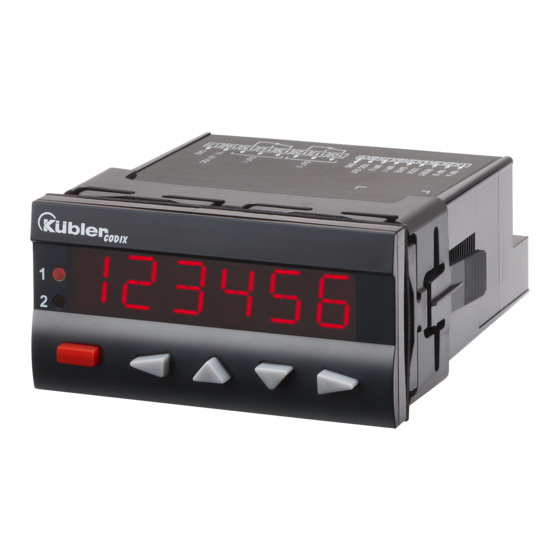
Elektronischer
CODIX 560
Vorwahlzähler
mit zwei Vorwahlen
Electronic Preset Counter
With two presets
Compteur à présélection
électronique
avec deux présélections
Contatore elettronico
a preselezione
con due preselezioni
Contador electrónico
de preselección
con dos preselecciones
Phone: 800.894.0412 - Fax: 888.723.4773 - Web: www.clrwtr.com - Email: info@clrwtr.com
Advertisement
Table of Contents

Related Manuals for Kubler CODIX 560


Summary of Contents for Kubler CODIX 560
- Page 1 Elektronischer CODIX 560 Vorwahlzähler mit zwei Vorwahlen Electronic Preset Counter With two presets Compteur à présélection électronique avec deux présélections Contatore elettronico a preselezione con due preselezioni Contador electrónico de preselección con dos preselecciones Phone: 800.894.0412 - Fax: 888.723.4773 - Web: www.clrwtr.com - Email: info@clrwtr.com...
-
Page 2: Table Of Contents
Table of Contents (German is the original version.) Preface Safety instructions and Warnings Use according to the intended purpose Mounting in a control panel Electrical Installation Cleaning and maintenance Description Display/Operating elements Inputs INP A, INP B RESET GATE LOC.INP MPI 1 / MPI 2 Outputs Output 1 / Output 2... - Page 3 11.4 Timer 11.5 Signal and Control Inputs 11.6 Outputs 11.7 Supply Voltage 11.8 Sensor Supply Voltage 11.9 Climatic Conditions 11.10 EMC 11.11 Device Safety 11.12 Mechanical Data 11.13 Connections 12 Scope of Delivery 13 Ordering Codes 14 Frequencies (typical) 14.1 Pulse Counter 14.2 Frequency Meter 15 Input modes: Pulse counting 16 Input modes: Timing...
-
Page 4: Preface
presets. Use for any purpose over and beyond this will Preface be deemed as not in accordance with its intended purpose and thus not complying with the Please read this instruction manual requirements. entirely and carefully before installation The application area for this device lies in industrial and start-up. -
Page 5: Electrical Installation
The device has been designed for overvoltage Electrical Installation category II. If higher transient voltages cannot be The device must be disconnected from excluded, additional protection measures must be any power supply prior to any taken in order to limit the overvoltage to the installation or maintenance work. -
Page 6: Display/Operating Elements
value 2 (‘Sub’ output operations). The reset input Input modes: Pulse counter: cnt.dir, up.dn, up.up, quad, quad2, can be inhibited in the programming menu. quad4, A/B, (A-B)/Ax100% Pulse counter: RESET input Frequency meter: A, A – B, A + B, quad, A/B, Frequency meter: no function (A-B)/Ax100%... -
Page 7: Selecting The Main Menus
Enter the main menu by pressing Change the count value using the ENTER key the UP key or the DOWN key. The first menu item in the main Press the ENTER key. menu appears in the display The new setting is again displayed flashing. -
Page 8: Setting The Basic Function
Select language for Help Text Totalising [A + B] INP A: count input add English INP B: count input add German (Deutsch) Quadrature input INP A: count input 0° When ‘Help Text ON’ is selected, a INP B: count input 90° running text in English or German Quadrature with pulse automatically appears after 3 sec. - Page 9 When the Lock input is activated, Electrical reset sets only the the setting of the preset values main counter to zero. and the programming are both Count mode SUBTRACTING inhibited. with automatic reset and Batch counter 7.8.3.2 Submenu for Output operations Output 2 (timed signal) active when main counter = zero Submenu for determining the...
-
Page 10: Tacho/Frequency Meter
When preset 2 is changed then Electrical Reset: preset 1 automatically tracks it. Always resets only the main counter. Reset to zero. Automatic reset to zero when Manual Reset: main counter = preset value 2. Resets the main counter (ACTUAL) and Preset 1 relative to Preset 2 auxiliary counters (BATCH or TOTAL), if the value of the main counter or the value of an... -
Page 11: Timer
INP A: Frequency input A Decimal point setting INP B: Frequency input B (determines the resolution) no decimal place Percentage differential 1 decimal place measurement [(A-B) / A in %] 0.00 2 decimal places INP A: Frequency input A 0.000 3 decimal places INP B: Frequency input B Moving average... - Page 12 Input mode Time measurement 7.8.5.2 Submenu for output operations (see also under 16.) Submenu for determining the operation of the outputs Start: Edge to INP A Stop: Edge to INP B Output operation (See also under 18.) Start: 1. Edge to INP B Stop: 2.
- Page 13 main counter = zero main counter = preset value 2. Batch counter counts the number Preset 1 relative to Preset 2 of automatic repetitions of preset 7.8.5.3 Submenu for configuration Output 1 active when batch Submenu for matching the input counter >...
- Page 14 7.8.5.5 Submenu for Preset 1 with positive direction and when count > Preset 1 Submenu Preset 1 ADD mode output operations: timed signal at Output1, Preset 1 ON/OFF becomes passive with positive Preset 1 ON direction and when count > Preset 1 and subsequently Preset 1 OFF and no function passive with negative direction...
-
Page 15: Operation
becomes passive when count < Operation zero (Deactivation only in negative direction). Switching the display during ADD mode output operations: operation timed signal at Output 2, Pressing the DOWN key or the becomes active with positive UP key once causes the name of direction and when count >... -
Page 16: Teach Function
8.2.2 Teach Function Default Parameters Note: Three default parameter sets have 1. In the programming menu, programme MPI been permanently stored; these can be input 1 or MPI input 2 (MP.INP.1 / MP.INP.2) adapted as required. With each to TEACH acknowledgment of the parameter sets, all 2. -
Page 17: Parameter Set Table
8.4.4 Parameter Set Table 10.1 Signal and Control Inputs P.SET1 P.SET2 P.SET3 N° Designation Function HLP.TXT. INP A Signal input A SL.LANG. INP B Signal input B FUNCT COUNT COUNT COUNT RESET Reset input INP.POL. LOCK Keypad lock FILTER GATE Gate input COUNT CNT.DIR... -
Page 18: Timer
Measuring principle 76.3 Hz Time interval 11.7 Supply Voltage (Period measurement) AC supply: 100 ... 240 V AC / max. 11 VA > 76.3 Hz Gate time 50/ 60 Hz, Tolerance ± 10% Gate time approx. 13.1 ms ext. fuse protection: T 0.1 A Measuring error <... -
Page 19: Connections
11.13 Connections AddAr AddTot SubAr SubTot Supply voltage and outputs: Plug-in screw terminal, 8-pin, RM5.00 Trail AddBat Core cross - section, max. 2.5 mm² SubBat TrailAr Signal and control inputs: Cnt.Dir 55 kHz 2.6 kHz 2.5 kHz Plug-in screw terminal, 9-pin, RM 3.50 Core cross - section, max. -
Page 20: Input Modes: Pulse Counting
15 Input modes: Pulse counting Function Diagram PNP: Count on rising edge NPN: Count on falling edge Note: No counting when GATE input is active P = Preset CNT.DIR Inp A: Count input Inp B: Count direction Add: Display 0 --> Preset Sub: Display Preset ->... - Page 21 Function Diagram PNP: Count on rising edge NPN: Count on falling edge Note: No counting when GATE input is active QUAD4 A 90° B Inp A: Count input Count on rising and on falling edges Inp B: Count input Count on rising and on falling edges, Reverse direction Add: Display 0 -->...
-
Page 22: Input Modes: Timing
16 Input modes: Timing Function Diagram PNP: Count on rising edge NPN: Count on falling edge INA.INB Inp A: Start Inp B: Stop Add: Display 0 --> Preset Sub: Display Preset -> 0 INB.INB Inp A: no function Inp B: Start/Stop Add: Display 0 -->... -
Page 23: Input Modes: Frequency Meter
17 Input modes: Frequency meter Function Diagram PNP: Count on rising edge NPN: Count on falling edge Inp A: Frequency input Inp B: no function A - B Inp A: Frequency input 1 Inp B: Frequency input 2 Formula: A - B A + B Inp A: Frequency input 1 Inp B: Frequency input 2... -
Page 24: Output Operations
18 Output operations Mode Diagram Mode Diagram Only in mode Additionally in mode ADD.AR SUB.AR ADD.BAT SUB.BAT ADD.TOT SUB.TOT Phone: 800.894.0412 - Fax: 888.723.4773 - Web: www.clrwtr.com - Email: info@clrwtr.com... - Page 25 Mode Diagram TRAIL TR.AR Phone: 800.894.0412 - Fax: 888.723.4773 - Web: www.clrwtr.com - Email: info@clrwtr.com...
-
Page 26: Help Texts
19 Help Texts PROG. NO PROGRAMMING PROG. START PROGRAMMING LANGU. MAIN MENU SELECT LANGUAGE HLP.TXT. HELPTEXT ON SL.LANG. DEUTSCH SL.LANG. ENGLISH FUNCT. MAIN MENU BASIC FUNCTION FUNCT. COUNT BASIC FUNCTION COUNTER FUNCT. TIMER BASIC FUNCTION TIMER FUNCT. TACHO BASIC FUNCTION TACHOMETER/FREQUENCY METER INPUT MAIN MENU INPUTS INP.POL. - Page 27 MODE SUB.AR MODE SUBTRACTING WITH AUTOMATIC RESET MODE SUB.BAT MODE SUBTRACTING WITH AUTOMATIC RESET + BATCH COUNTER MODE SUB.TOT MODE SUBTRACTING WITH AUTOMATC RESET + TOTAL COUNTER CONFIG. MAIN MENU CONFIGURATION FACTOR MULTIPLICATION FACTOR DIVISO. DIVISION FACTOR T.MODE TIME RANGE SECONDS T.MODE TIME RANGE MINUTES T.MODE...
-
Page 28: Dimensional Drawings
20 Dimensional Drawings Dimensions in mm [inch] Rear view: Panel cut-out: +0.8 +0.031 [3.622 Phone: 800.894.0412 - Fax: 888.723.4773 - Web: www.clrwtr.com - Email: info@clrwtr.com...
Need help?
Do you have a question about the CODIX 560 and is the answer not in the manual?
Questions and answers