
Related Manuals for ELMETRON CX-401


Summary of Contents for ELMETRON CX-401
- Page 1 WATERPROOF MULTIFUNCTION METER CX- 401 USER’S MANUAL WATERPROOF MULTIFUNCTION METER CX-401 Before use please read the instruction carefully!
-
Page 2: Table Of Contents
TABLE OF CONTENT I. Introduction 1. Exploitation notices 2. The characteristic of the meter 3. What is the meter designed for 4. Outside view 5. Switching the meter on and off 6. Preparation to work 6.1. Choosing the kind of temperature compensation 6.2. - Page 3 - 2 - 19. Salinity and TDS measurement 19.1. Salinity measurement with conversion to NaCl or KCl content 19.2. Determining the W coefficient 19.3. The measurement of salinity with conversion to TDS IV. Oxygen concentration measurement 20. Basic information about dissolved oxygen measurement 21.
-
Page 4: Introduction
- 3 - I. Introduction... -
Page 5: Exploitation Notices
- 4 - 1. EXPLOITATION NOTICES Dear User! We present you a device distinguished by accuracy according to the technical data and by a high stability of the displayed results. We believe that the measurements will not cause you any trouble and that the meter will operate without any inconvenience. -
Page 6: The Characteristic Of The Meter
- 5 - 2. THE CHARACTERISTICS OF THE METER The multifunction meter CX-401 belongs to the newest generation of measuring devices which offer wide range of additional functions. The meter ensures high accuracy and repeatability of the readings. Two kinds of power source: battery and power adapter enable work in field and long-lasting measurements in the laboratory. -
Page 7: What Is The Meter Designed For
- 6 - 3. WHAT IS THE METER DESIGNED FOR Waterproof multifunction meter CX-401 is precise and easy to use meter designed for hydrogen ion concentration measurements in pH units, Oxidation Reduction Potential (mV) conductivity, in µS/cm or mS/cm, dissolved oxygen in water in % of saturation or mg/l and atmospheric pressure measurement in hPa. -
Page 8: Outside View
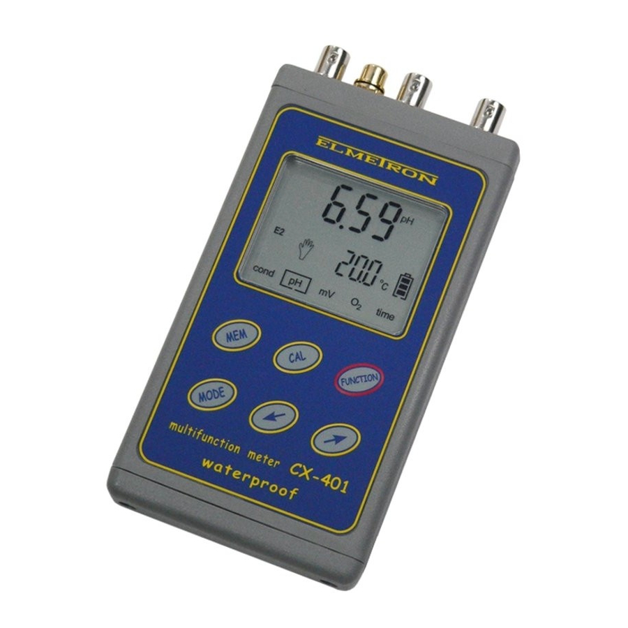
- 7 - 4. OUTSIDE VIEW. On the front wall of the meter there is a LCD display (pic. 1) on which depending on the chosen function following symbols are displayed: result of the conductivity or salinity measurement; result of the pH measurement in pH units; result of the mV measurement in mV;... - Page 9 - 8 - The keyboard has the keys as follows: - to change the function, and switch the meter on, off. - short pressing in MODE/P.CAL mode enables choosing points of calibration to change their value. - longer pressing of this button enters the calibration mode (CAL symbol displayed).
- Page 10 - 9 - Pic. 2.
-
Page 11: Switching The Meter On And Off
- 10 - 5. SWITCHING THE METER ON AND OFF The meter is switched on by pressing the button. The meter tests the memory and display on which all symbols are displayed. Pic. 3 If the test was successful, after about 1.5 s the meter switches it self automatically to the measuring mode, in which it was switched off. -
Page 12: Preparation To Work
- 11 - 6. PREPARATION TO WORK Before starting the work one should: - join the power adapter plug to the P input, if work with the power adapter is planned; - to BNC-50 input F join the ready to work combination pH electrode, redox electrode or the dissolved oxygen sensor;... -
Page 13: Changing The Resolution Of The Measurement
- 12 - 6.2. Changing the resolution of the measurements The measurement results may be displayed with chosen resolution. To change it one should: in the measuring mode press the button, a (resolution) sign will be displayed. (Pic. 4) Using keys one may choose: - (low) resolution of the measurement;... -
Page 14: Ph Measurement
- 13 - II. pH measurement... -
Page 15: Preparation Of The Ph Electrode
- 14 - 7. PREPARATION OF THE pH ELECTRODE The electrode should be prepared to work according to the producer instructions. If the instructions weren’t given please follow the steps: - new electrode should be put into distilled water or in saturated KCl solution for about 5 hours: - Before starting the measurements protecting rings (if used in this kind of electrode) should be removed. -
Page 16: Calibration Of The Ph Electrode
- 15 - 8. CALIBRATION OF THE pH ELECTRODE Before starting the measurement with new electrode, after long-lasting using, or before making measurements which require higher accuracy the electrode connected with the meter should be calibrated. Results of measurements done without calibration will have a great error. - Page 17 3 buffer solutions with values in range given in table 2 – calibration points 2, 3 and 4. In case of accurate measurements in the whole range it is recommended to calibrate the electrode in all 5 points given in the table. IN CX-401 characteristic of the electrodes is approximated linearly between the calibration points.
-
Page 18: Introducing The Ph Values Of The Buffer Solutions
- 17 - The order of using the buffer solutions is freely chosen. The user may choose two independent ways of action: 1. enter the value of pH buffer solutions depending on the actually used buffers, in the range given for each point of calibration; 2. - Page 19 - 18 - Range of possible changes is given in the table 2. There is possibility to introduce the values of buffer solutions with two or three decimal places. The meter doesn’t allow for introducing pH values in ranges other than those given in the table 2.
-
Page 20: Automatic Change Of The Ph Value Of Buffer Solution
- 19 - Together with the temperature change value of the pH buffer solution changes. The producers often give the values of the solutions in few temperatures. This data may be used and the meter may be calibrated in other temperature than 20 o C, by introducing to the meters memory value of the buffer which responds to the chosen temperature. - Page 21 - 20 - Table 3. Kind of buffer solution Temp. oxalate phthalate phosphate di-sodium calcium tetraborate hydroxide 1.666 4.003 6.984 9.464 13.423 1.668 3.999 6.951 9.395 13.207 1.670 3.998 6.923 9.332 13.003 1.672 3.999 6.900 9.276 12.810 1.675 4.002 6.881 9.225 12.627 1.679...
-
Page 22: The Actions During Calibration
- 21 - 8.3. The actions during calibration One should: a. Choose the resolution with which the buffer solution value will be introduced. Depending on the fact weather the buffer solutions have the pH value given with 2 or 3 decimal places one should choose the right resolution. Using button choose the pH function, next press the button a... - Page 23 - 22 - – automatic change of the stored pH value of the buffer solution by it’s temperature change according to table 3. – setting the value of the buffer solution in the range given in table 3. Pic. 5 After choosing the symbol one should press the button and start the...
- Page 24 - 23 - Pic. 6. To pass to the second point of calibration press the button in the lower row a , symbol will be displayed (point 2) and in the upper row the stored in this point value of buffer solution. When checking or changing the value in the next steps please follow the instructions given above.
-
Page 25: Calibration With Automatic Temperature Compensation
- 24 - After choosing the number of electrode according to the point b, press the button and start the calibration on the buffer solutions. Under each of the three numbers of electrode one may calibrate next electrodes in pH buffers with different values, after earlier setting those values and storing them under the chosen number. - Page 26 - 25 - In this moment the result will blink what will inform about storing the calibration result, in this same time in the upper row the corrected value of measurement will be displayed – it will be equal the value of used buffer solution (pic.
-
Page 27: Calibration With Manual Temperature Compensation
- 26 - 8.5. Calibration with manual temperature compensation To start the calibration with manual temperature compensation one has to disconnect the temperature probe. Disconnecting the temperature probe switches the meter to manual compensation. On the display the entered value of the temperature is displayed, not the measured one. -
Page 28: Ph Measurement
- 27 - 10. pH MEASUREMENT Before starting the measurement one has to prepare the meter for work (chapter 6) and pH electrode (chapter 7). Good condition of the electrode is the main condition of correct measurements. If the electrode was calibrated and is joined with the meter it is advisable to check whether the number of the electrode is this same as the number of the characteristic chosen from the memory. -
Page 29: Measurement With Manual Temperature Compensation
- 28 - 10.2 Measurements with manual temperature compensation Disconnecting the temperature probe from the meter switches the meter to the manual temperature compensation mode (symbol is displayed ). Measurement with manual temperature compensation is similar to the measurement with ATC, the difference is that using buttons one enters the temperature measured with other thermometer. -
Page 30: Notices About The Temperature Compensation And Interpretation Of The Results
- During measurements in sewage some chemical reactions, which change the result, may occur; Very small differences may be caused by the meters accuracy. The CX-401 accuracy is ±0.002 pH, ±1 digit, what practically means that in extreme situation results of 2 measurements may differ for 0.005 pH and this will be an acceptable error, because 1 measurement will be made with -0.002 pH error... - Page 31 - 30 - If after making a two point calibration in pH buffers 7.00 pH and 4.00 pH (acidic conditions), the results are checked in 9.00 pH (alkali conditions), in some cases the result may be 8.90 pH or 9.10 pH. This may occur when the electrode has unsymmetrical characteristic.
-
Page 32: Conductivity And Salinity Measurement
- 31 - III. Conductivity and salinity measurement... -
Page 33: Basic Information About The Conductivity Measurement
CONDUCTIVITY MEASUREMENT The conductivity measurement is based on applying a voltage with proper frequency between two electrodes and measuring it. In the CX-401 the frequency depends on the measuring range and may vary from 100 Hz up to 10 kHz. Depending on the kind of the measured liquid, it’s concentration and the temperature, the voltage flow is easier or harder. -
Page 34: Preparation To Work
- 33 - The conductivity, despite the electronic precision, should always be treated as burdened with some error, which depends on the error of conductivity cell (it’s linearity), temperature and first of all depending on the α coefficient during measurements in temperatures different than 25 13. - Page 35 - 34 - - measurement result counted to NaCl in g/l (pic. 10); Pic. 10. - measurement result counted to KCl in g/l (pic. 11); Pic. 11. - measurement result counted to TDS in g/l (pic. 12). Pic. 12.
-
Page 36: Entering The W Tds Coefficient
- 35 - In case of salinity measurement ( ), short pressing of the button chooses displaying the result in % of weight concentration or g/l. By the symbol with name of the salt a % or g/l symbol will be displayed. - by pressing the enter the measuring mode. -
Page 37: Choice And Maintenance Of The Conductivity Cell
14. CHOICE AND MAINTENACE OF THE CONDUCTIVITY CELL 14.1. The cell choice The conductivity measuring range in CX-401 meter is 0 – 1999 mS/cm. The meter co-operates with conductivity cells with constant K = 0.010 ÷ 19.99 cm -1 and BNC-50 connector. Depending on the required measuring range it is necessary to choose the right cell with constant K which enables receiving correct results. -
Page 38: The Conductivity Cell Maintenance
- 37 - 14.2. The conductivity cell maintenance To receive stable results it is advised to store the cell for few hours before the measurement in water, especially this is required in case of distilled water measurements. The conductivity probe maintenance mainly consists of accurate washing the inside of the measuring cell with distilled water. -
Page 39: Calibration
K of the conductivity probe. This value may be given by the cell producer or may be determined using the CX-401 meter after making the calibration in the sample solution. To make the calibration one should:... -
Page 40: Calibration With Use Of Sample Solution
- 39 - 15.2. Calibration with use of sample solution The meter enables one point calibration in the freely chosen sample solution. To decrease the error it is recommended to use solutions with value close to the forecasted value of measurement. It is required to use high quality sample solutions. - Page 41 - 40 - - wait till the stabilisation of the value and press the button. Pulsating of the results informs about storing in the memory. If symbol will be displayed it is necessary to check the introduced value of the sample solution. - exit the calibration mode by pressing the button.
-
Page 42: The Simplified Way Of Determining The Α Coefficient
- 41 - 16. THE SIMPLIFIED WAY OF DETERMINING THE α COEFFICIENT The knowledge of α coefficient has a crucial significance during measurements in temperatures different than 25 o C. This coefficient is changing together with the temperature and concentration. Below we are giving values of α... -
Page 43: Entering The Α Coefficient Value
17. ENTERING THE α COEFFICIENT VALUE The α coefficient range in CX-401 is 0 ÷ 10.00 % with accuracy of regulation 0.01 % / o C. For the measurements it is possible to adopt the most often used temperature coefficient α... -
Page 44: The Conductivity Measurement
- 43 - 18. THE CONDUCTIVITY MEASUREMENT 18.1. The conductivity measurement without temperature compensation An accurate conductivity measurement should be done without the temperature compensation. The measured solution should be brought to temperature of 25 o C. During the control it is possible to use the temperature probe. In case of work without temperature probe it is necessary to introduce the temperature value with buttons. -
Page 45: The Measurement With Temperature Compensation
- 44 - 18.2. Conductivity measurement with automatic temperature compensation In case of measurement with automatic temperature compensation one should: - connect the conductivity and temperature probes to the right connectors F1 and t (pic. 2); - turn the meter on with button. -
Page 46: The Measurement With Manual Temperature Compensation
- 45 - 18.3. Conductivity measurement with manual temperature compensation The measurement with manual temperature compensation may be done in stable work conditions, ex. during measurements in laboratory, especially with use of thermostat, or in case of the temperature probe damage. Disconnecting temperature probe switches... -
Page 47: Salinity And Tds Measurement
18.174 15.000 17.46 In CX-401 microcontroller takes into consideration the real dependence between the conductivity and salinity what greatly lowers the error. There is possibility of counting the salinity in NaCl or KCl, because the dependence for this two salts is a bit different. -
Page 48: Salinity Measurement With Conversion To Nacl Or Kcl Content
- 47 - The results will be more accurate for homogeneous solutions (NaCl, KCl). Determining the concentration of salts mixture with unknown composition in most cases is counted to NaCl . To check the usefulness of water for home or industrial use usually determining of TDS is used. -
Page 49: Determining The W
- 48 - 19.2. Determining the W coefficient For salinity measurement with conversion to TDS content it is necessary to determine the W coefficient and enter it to the meter’s memory. To do so it is necessary to make the conductivity measurement of the tested water with exactly given volume or weight. - Page 50 - 49 - IV. Dissolved oxygen measurement...
-
Page 51: Basic Information About Dissolved Oxygen Measurement
- 50 - 20. BASIC INFORMATION ABOUT DISSOLVED OXYGEN MEASUREMENT The measurement of dissolved oxygen in water solutions is performed using an oxygen sensor. The basic element of the sensor is a Teflon semi-permeable membrane, which enables the penetration of oxygen contained in the measured solution, into the electrolyte –... - Page 52 Even the best oxygen sensors have so called drift about ±1%/24 h. Wide measuring range in multifunction meter CX-401 enables measurements of waters which are permeated with oxygen. This situation occurs when in the water plants are blooming and growing, in this moment during the photosynthesis process large quantities of oxygen are produced.
-
Page 53: The Oxygen Sensor
- 52 - 21. THE OXYGEN SENSOR The meter may co-operate with galvanic oxygen sensor. Conventionally it co- operates with the sensor made by ELSENT with accuracy of ±1%, if the measurement is done in this same temperature as the calibration. The accuracy of measurement decreases together with growing of the difference between the temperature of calibration and temperature of measurement. -
Page 54: Changing The Unit
- 53 - 22.2. Changing the unit The measurement result may be displayed in % of the oxygen saturation or in mg/l. To choose the unit one should: - in the oxygen measuring mode press the button till displaying in the lower row of LCD (unit) sign;... - Page 55 - 54 - 22.3.1. Automatic introduction of salinity value The meter enables automatic introduction of measured solution salinity. To use this feature one should: - by pressing the button enter the conductivity measuring function; - measure the salinity of solution in NaCl (accurate description in chapter 19.1);...
- Page 56 - 55 - mS/c mS/c mS/c 0.49 16.87 34.34 1.00 17.52 34.99 1.52 18.17 35.64 2.08 18.82 36.28 2.63 19.46 36.93 3.19 20.11 37.58 3.74 20.76 38.23 4.29 21.41 38.87 4.85 22.05 39.52 5.40 22.70 40.17 6.00 23.35 40.81 6.61 23.99 41.46 7.21...
-
Page 57: Automatic Compens. Of The Atmospheric Pressure Influence
- 56 - 22.4. Automatic compensation of the atmospheric pressure influence The value of oxygen saturated in water determined in mg/l depends directly on the atmospheric pressure value, this means that 10% pressure change causes oxygen saturation change for 10%. The meter ensures automatic compensation thanks build in atmospheric pressure sensor. -
Page 58: Calibration Of The Oxygen Probe
- 57 - 23. CALIBRATION OF THE OXYGEN PROBE In order to eliminate the measurement error arising from the individual characteristic of the sensor a calibration of the device should be carried out. This procedure should be performed always before operation with a new sensor, after replacing the membrane or for special requirements concerning the measurement accuracy. - Page 59 - 58 - Starting the calibration under the chosen sensor number deletes the characteristic stored in memory under this number. If after choosing the sensors number and entering the calibration mode one will exit this mode the stored characteristic will be deleted and standard characteristic will be applied.
-
Page 60: Oxygen Concentration Measurement
- 59 - 24. OXYGEN CONCENTRATION MEASUREMENT Before starting the oxygen concentration measurement the meter should be prepared for work (chapter 6) and the oxygen sensor calibrated (chapter 23). As mentioned the measurement in % saturation does not require additional measurements associated with the temperature, salinity and atmospheric pressure. -
Page 61: Measurement With Automatic Temperature Compensation
- 60 - 24.1. Measurement with automatic temperature compensation To make the measurement with automatic temperature compensation one should: - connect the temperature probe with the meter; - insert the oxygen and temperature probes to the measured solution; - turn the meter on with button;... - Page 62 - 61 - V. Atmospheric pressure measurement...
-
Page 63: Atmospheric Pressure Measurement
- 62 - 25. ATMOSPHERIC PRESSURE MEASUREMENT The meter enables atmospheric pressure measurement. To read it’s value one should: - turn the meter on by pressing the button; - with button choose the oxygen concentration mode (O - press the button till moment of displaying in the lower row of LCD the (pressure) sign;... -
Page 64: Orp (Mv) And Temperature Measurement
- 63 - VI. ORP and temperature measurement... -
Page 65: Orp (Voltage) Measurement
- 64 - 26. ORP (VOLTAGE) MEASUREMENT Multifunction meter CX-401 is accurate mV meter (Oxidation Reduction Potential). The measurement may be done with special redox electrode or during titration. The result may be checked after choosing the mV mode with button (pic. -
Page 66: Other
- 65 - VII. Other... -
Page 67: Clock, Date, Auto Switch Off Function
- 66 - 28. CLOCK, DATE, AUTO SWITCH OFF FUNCTION After choosing the time mode with button the meter will display the actual time. By pressing the button one may display the date, auto off time and battery condition. 28.1. Time display The hour is displayed in two rows. -
Page 68: Checking The Battery Condition
- 67 - 28.4. Checking the battery condition Disconnect the power adapter, enter the time function and press the button till moment of displaying in the upper row a symbol (pic. 29). In the lower row the condition of battery described in % will be displayed: - 100% the battery is full - 0% the battery should be replaced In case of using the power adapter instead of the... -
Page 69: Storage And Readout Of The Results
There is also possibility to printout on request the result of measurement which is being done at this moment. For printing an Interface EI-401 (Elmetron) is required. Before starting the work it is necessary to choose the storing or printing function and determine the way of displaying the result. - Page 70 - 69 - With button choose in lower row symbols. (pic. 30) Choosing activates automatic storing of the results and single, after every pressing of button - time interval during series taking (pic.31). Pic. 31. Value of the time interval is displayed in the upper row of digits, and the informative symbol in the lower row.
-
Page 71: Storing The Single Measurements In The Memory
- 70 - 29.3. Storing the single measurements in the memory If according to previous section storing of single results was chosen, every pressing of button stores the measured result. The results are stored as the next ones after the last stored. If someone was checking the earlier stored results and didn’t return to the last one the results won’t be deleted and the value will be stored after the last measurement. -
Page 72: Reviewing Of The Results
- 71 - 29.5. Reviewing of the results Reviewing of the stored results is started from the measuring mode, by pressing and holding the , button until the number of last stored result on turns with it’s value will be showed. Every pressing of the button shows the next or previous number and result with time and date if... -
Page 73: Printouts On The Printer
- 72 - 30. PRINTOUTS ON THE PRINTERS In upper wall of the meter there is a RS-232 input which enables joining the meter with printer. To connect a printer with Centronics connector it is necessary to use an adapter EI - 401 which is offered as additional equipment. The adapter is connected with the meter by the RS-232 connector (pic.2) and with the printer by standard cable. -
Page 74: Printout Of The Results Stored In The Memory
- 73 - 30.2. Printout of the results stored in the memory To print the results stored in the memory: - join the printer with the meter using the RS-Centronics adapter (as described on the beginning of the chapter); - switch the meter and printer on; - choose the printout format (point 29.2.d) and way of printing –... -
Page 75: Co-Operation With The Pc
- 74 - CO-OPERATION WITH THE PC Connecting the meter with a PC enables storing data directly on the computer, what eliminates the limitation to 200 results. The PC should be equipped with serial RS-232 connector (typically COM2) configured for 9600 b/s, 8 bit, 1 even bit, 1 stop bit, lack of steering the transmission. -
Page 76: Technical Data
- 75 - 33. TECHNICAL DATA pH measurement: Accuracy range resolution (±1 digit) -2.000 ÷ 16.000 pH 0.001 / 0.01 pH ±0.002 pH Ω INPUT IMPEDANCE: TEMPERATURE COMPENSATION: manual/automatic -5.0 ÷ 110.0 o C RANGE OF COMPENSATION: pH ELECTRODE CALIBRATION: automatic, in 1 ÷... - Page 77 - 76 - CONDUCTIVITY MEASUREMENT: Accuracy ranges resolution Frequency (±1 digit) 0.000 ÷ 19.999 µS/cm 0.001 / 0.01 µS/cm ±0.1 % 100 Hz 20.00 ÷ 199.99 µS/cm 0.01 / 0.1 µS/cm ±0.1 % 1 kHz 200.0 ÷ 1999.9 µS/cm 0.1 / 1 µS/cm ±0.1 % 2 kHz 2.000 ÷...
- Page 78 - 77 - ATMOSPHERIC PRESSURE MEASUREMENT: Accuracy* range resolution (±1 digit) ±2 hPa 800 ÷ 1100 hPa 1 hPa Atmospheric pressure sensor NPP-301 TEMPERATURE MEASUREMENT: Accuracy* Range Resolution (±1 digit) - 50.0 ÷ 199.9 o C 0.1 o C ±0.1 o C * accuracy of the meter.
-
Page 79: Equipment
- 78 - 34. EQUIPMENT The standard equipment for the CX-400 meter is: 1. Temperature probe Pt-1000B (standard); 2. Plastic container for the meter electrode and temperature probe; 3. Users manual with warranty. The additional equipment available for this meter is: 1. - Page 80 W A R R A N T Y The “ELMETRON” company ensures a 24 months warranty for the multifunction meter CX-401 number: ..........In case of damage the producer will repair the meter within 14 days from the day of delivery.
Need help?
Do you have a question about the CX-401 and is the answer not in the manual?
Questions and answers