Table of Contents
Advertisement
Quick Links
Advertisement
Table of Contents
Troubleshooting

Related Manuals for SLE SLE4000


Summary of Contents for SLE SLE4000
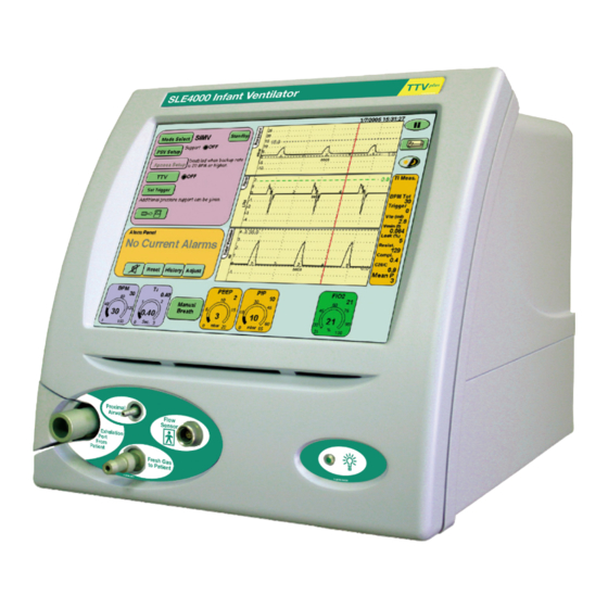
- Page 1 SLE4000 Model K service manual Version 4.3.1 & 4.3.2 software...
- Page 2 All rights reserved. No part of this publication may be reproduced, stored in any retrieval system, or transmitted in any form or by any means, electronic, mechanical, photocopy, recording or otherwise, without prior permission of SLE. © Copyright SLE 21/06/2011. Manual: SM0032 Issue 2 SLE Part Nº:...
-
Page 3: Table Of Contents
10. A0763/4B Monitor and control board ..............52 10.1. A0763/4B board progammable devices ............52 10.2. A0763/4B Board Hardware Identifier............53 11. Electrical Safety Testing of the SLE4000 ..............57 12. PSU Testing ......................61 13. Ventilator Power up and Power down..............64 14. - Page 4 14.1. Battery indicator ....................65 15. Extended storage ....................67 16. Maintenance and Overhaul ..................70 16.1. Preventative Maintenance Kit ...............70 16.2. 12 & 36 month preventative maintenance procedure ........72 16.3. 24 month and 48 month overhaul procedures ..........80 16.4. 24 month / 10,000 hour overhaul procedure..........82 16.5.
- Page 5 25. EMC compliance ..................... 192 25.1. Electromagnetic immunity ................193 25.2. Recommended separation distances between portable and mobile RF communications equipment and the SLE4000 ............195 26. Ventilator labelling ....................196 26.1. SLE4000....................... 196 27. Electrical Block Diagram ..................198 28.
- Page 6 Appendix 5. VueLink .....................300 37. VueLink Technical Data ..................300 37.1. Glossary......................300 37.2. Connecting the SLE4000 to the VueLink patient monitor ......300 37.3. Parameter Descriptions ................301 37.4. Data transferred to the VueLink system from the SLE4000......302 37.5. Alarm and inoperative indications ..............304 37.6.
-
Page 7: Warnings And Cautions
Warnings and Cautions (Model K) Page 7... -
Page 8: Warnings And Cautions
1. Warnings and Cautions 1.1 Warnings The electronic and pneumatic units of the SLE4000 infant ventilator are sealed at the factory with two Warranty Void If Label Broken seals. If the ventilator is subject to a warranty agreement do not attempt to carry out any procedure that would involve breaking these seals. -
Page 9: Cautions
The equipment is not suitable for use with, or in the presence of flammable anaesthetic mixtures. The SLE4000 flow monitoring system is calibrated to work in an air / oxygen mixture, the use of other gas mixtures may affect the flow monitoring accuracy of the ventilator. - Page 10 11. The SLE4000 contains several batteries, three 2 cell sealed lead acid batteries and 2 AA alkaline batteries. At the end of their useful life these batteries should be disposed of in accordance with local authority guidelines. 12. Apart from the batteries, the ventilator and accessories do not contain any hazardous components therefore no special precautions are required for their disposal.
- Page 11 Principles of Operation (Model K) Page 11...
-
Page 12: Principles Of Operation
2. Principles of Operation The SLE4000 infant ventilator consists of an electronic system in the upper section of the ventilator and a pneumatic system in the lower. 2.1 Electronic System The electronic system comprises three autonomous subsystems, one responsible for monitoring the patient, one responsible for controlling the valves of the pneumatic system and one for the user interface (touchscreen and displayed data). -
Page 13: Pneumatic System
2.2 Pneumatic System The pneumatic system comprises of the tubing and electro-mechanical valves necessary to provide the gas in conventional ventilation modes. The two gas controlling functions are blending and pressure generation 2.2.1 Blending The method used for blending air and oxygen in known proportions is to pressure regulate the two supplies (air and oxygen) so they produce equal flow rates and then allow each supply into a mixing chamber for a time period equivalent to the proportions required. - Page 14 This page is intentionally blank. Page 14 (Model K)
-
Page 15: Description Of Symbols
Description of Symbols (Model K) Page 15... -
Page 16: Description Of Symbols
3. Description of Symbols Symbol Description Type BF connection (Situated on front panel) Read manual (Situated on rear panel) Date of Manufacture (Appears on serial number label) Do not dispose of as general waste (WEEE directive) (Appears on serial number label) EEC conformity marking showing compliance with the Medical Devices Directive (Appears on serial number label) Indicates the mains power switch... - Page 17 Symbol Description Indicates a note in the manual Indicates a caution in the manual Check list item. (Model K) Page 17...
- Page 18 This page is intentionally blank. Page 18 (Model K)
- Page 19 Equipment List (Model K) Page 19...
-
Page 20: Equipment List
4. Equipment list To service the SLE4000 infant ventilator the service personnel will require the following equipment. Items marked with an SLE part number can be obtained by contacting the service department. • Electronic engineers tool kit. • Calibration analyser (calibrated in mbar) ..SLE Part Nº: N2830 •... - Page 21 Engineering Mode Software (Model K) Page 21...
-
Page 22: Engmode
5. ENGMODE The SLE4000 ventilator is calibrated via two calibration programs, one for the ventilator and one for the Touch screen. The calibration programs are accessed via the Controller Services panel in the user interface. Note: The calibration program is common to SLE4000 and SLE5000 ventilators. - Page 23 Step 4 Press the Controller button. Step 5 Enter the code supplied by SLE into the ventilator, via the controller services panel to activate the calibration program. Begin psv is the A button. End psv is the B button. Apnea sup is the C button.
-
Page 24: Ventilator Calibration Program
5.2 Ventilator Calibration Program The calibration program has four main functions. 1. Sensor Calibration 2. Jet Calibration 3. O & Flow System Calibration 4. Elapsed Time Reset. 5. Language Selection 6. Exit 5.2.1 Sensor Calibration The sensor calibration panel allows the following sensors to be calibrated. Controller The setting of the block and leak sensor... -
Page 25: O 2 & Flow System Calibration
5.2.2 Jet Calibration The jet calibration panel allows the forward jet, reverse jet and mean jet to be adjusted. Also contained within this panel are the controls to adjust the inspiratory and expiratory leading edges of the CMV wave form. 5.3 O &... -
Page 26: Reset Elapsed Time
5.4 Reset Elapsed Time The reset elapsed time panel allows the ventilators time counter to be reset to zero days and minutes. This function is only used at the 20,000 hour overhaul. 5.5 Language Selection The “Language Selection Program” panel displays the languages choices that can be installed. -
Page 27: Activation Of Language Selection Program Form User Interface
* Please contact SLE or your distributor for information on the availability of secondary languages. To install a secondary language select the language required. The name of the selected... -
Page 28: Touch Screen Calibration Program
Warning: Failure to carry out the touch screen calibration correctly can cause the ventilator to become unusable. A failed touch screen calibration can only be corrected by connection of a specialist device. Please contact SLE or your distributor in this situation. Page 28 (Model K) - Page 29 Component Replacement (Model K) Page 29...
-
Page 30: Component Replacement Procedure
• PC board ..........SLE Part Nº: N6631/LX800 • CAN card ..........SLE Part Nº: N6634 • Computer /display control assembly ..SLE Part Nº: L0275/OEM2 • Serial controller (Touch screen) ....SLE Part Nº: N6631/2216 • Control and monitor board ......SLE Part Nº: A0763/4B •... -
Page 31: Preparing The Sle4000
Caution: the SLE4000 ventilator weighs 21.8kg fully assembled. Care should be taken when handling the ventilator. If preparing to work on both the electronic and pneumatic units of the SLE4000 remove the ventilator from the stand and place it on a flat stable surface. The SLE4000 ventilator is attached to the trolley or pole by two screws with shake proof washers. - Page 32 Warning: If the ventilator is under a warranty agreement removal of the inner covers may void the agreement. Please refer to the warranty documentation. Step 3 Remove the screws (B) (2 screws) (C) (4 screws) to release the electronic inner cover. Step 4 Remove the screws (D) (6 screws) to release the pneumatic unit base plate.
-
Page 33: Component Replacement (Electronic Unit)
8. Component Replacement (Electronic unit) 8.1 N6631/21/CF/50 Compact Flash Card 1. Slide the compact flash card (B) out of its socket in the direction of the arrow. 2. Insertion of the compact flash card is the reverse of removal. Caution: Do not force the compact flash card out of the carrier, as it may catch on the connector mounted on the edge of the board Setup: If the same or new card is inserted software then a full functional test is required for this component. -
Page 34: N6634/Oem2 Can Card
8.3 N6634/OEM2 CAN Card Warning: The CAN card is a static sensitive device. 1.The CAN card (A) is already loose from the removal of the N6331/LX800 PC board. 2. Disconnect the CAN card ribbon cables (B). 3. The CAN card (A) can now be removed. 4. -
Page 35: L0275/Oem2 Computer/Display Control Assembly
8.5 L0275/OEM2 Computer/Display Control assembly Warning: The Computer/Display Control assembly is a static sensitive device. 1. Remove the PCB locking screw. This will allow the top board assembly to slide forward a small amount which gives better access to the edge connectors of the top board. -
Page 36: A0763/4B Control/Monitor Board
8.6 A0763/4B Control/Monitor Board Warning: The Control/Monitor Board is a static sensitive device. 1. Remove the L0275/OEM2 Computer/Display Control assembly as described in section 8.5. 2. Disconnect the following cables. 3. CAN card link ribbon cable controller side (A). (P3) 4.CAN card link ribbon cable controller side (B). -
Page 37: M0915 Power Supply Unit
8.7 M0915 Power Supply Unit 1. Disconnect the main power supply. 2. Remove the four fixing screws. 3. Disconnect the battery monitor cable (A). 4. Disconnect the main loom power cable (B). 5. Disconnect the battery monitor cable (C). 6. Disconnect the Mains Present LED cable (D). -
Page 38: M0901 Batteries
8.8 M0901 Batteries 1. Remove the L0275/OEM2 Computer/Display Control assembly as described in section 8.5. 2. Remove the Control /Monitor board as described in section 8.6. 3. Disconnect all the battery terminal leads. 4. Remove the four retaining screws for the first two battery blocks. -
Page 39: A0761 Transducer Pcb Assembly
8.9 A0761 Transducer PCB Assembly Warning: The Transducer PCB is a static sensitive device. Note: Screen removed for clarity. 1. Remove the L0275/OEM2 Computer/ Display Control assembly as described in section 8.5. 2. Remove the Control/Monitor board as described in section 8.6. 3. -
Page 40: N6631/13 Inverter Pcb
8.10 N6631/13 Inverter PCB Warning: The Transducer PCB is a static sensitive device. Note: Screen removed for clarity. 1. Remove the L0275/OEM2 Computer/Display Control assembly as described in section 8.5. 2. Remove the Control/Monitor board as described in section 8.6. 3. -
Page 41: N6631/02 Lcd & N6631/05 Touch Screen
8.11 N6631/02 LCD & N6631/05 Touch Screen 1. Remove the L0275/OEM2 Computer/Display Control assembly as described in section 8.5. 2. Remove the Control / Monitor board as described in section 8.6. 3. Remove the 4 screws (A) retaining the screen tie bars. 4. - Page 42 16. Remove the 2 nuts, washers (K) and screws (L) retaining the left hand side of the LCD / touch screen assembly. 17. Separate the LCD / touch screen assembly from the mounting plate. 18. Disconnect the connecting cable (M) from the rear of the LCD assembly. 19.
-
Page 43: Component Replacement (Pneumatic Unit)
9. Component Replacement (Pneumatic unit) 9.1 Duckbill and conical filters. Note: The air inlet connector is used to illustrate the process, the procedure is the same for the O inlet connector. Note: The O connector is a left hand thread and the Air connector is a right hand thread. - Page 44 9.1.1 N0288/01 blender manifold block Location in pneumatic unit Part number: N0288/01 1. Disconnect and remove the following tubes: (A) fresh gas supply tube, (B) fresh gas dump tube, (C) O cell sample dump tube, (D) fresh gas to PRV1 tube, (E) blender O supply tube, (F) forward jet supply tube,...
- Page 45 2. Remove the nuts and washers (I) to release the blender manifold assembly (J). 3. Remove the solenoid coil (K) from the solenoid base on the pressure regulator assembly (L). 4. Lift the manifold assembly (J) off the four chassis studs. Note: Leave the old oxygen cell fitted to the assembly.
- Page 46 9.1.2 N0280/02/S46 Pressure regulators (PR4 & PR6) Location in pneumatic unit Part number: N0288/02 1. Disconnect the following tubes: (A) mean jet delivery tube (B) blended gas supply tube (C) forward jet delivery tube 2. Disconnect the electrical connectors from PR4 (D) and PR6 (E). PR4 cable is tagged 4.
- Page 47 4.Remove the four nuts and washers (H) securing the pressure regulator manifold assembly. 5. To remove the pressure regulators (I & J) from the manifold block (K) remove the screws (L), two per regulator. Note: that the ‘O’ rings (M) will be released once the regulator has been removed.
- Page 48 9.1.3 N0280/05 inlet air pressure regulator 1.Remove the remaining tube (A) from the inlet air pressure regulator (B). 2. Remove the two nuts (C). 3. Withdraw the regulator (B). 4. Assembly is reversal of removal. Setup: Full system calibration is required for this component.
- Page 49 9.1.4 N0280/06 inlet oxygen pressure regulator 1. Disconnect the tube (A) from the inlet manifold elbow (B). 2. Disconnect the tube (C) from the inlet manifold elbow (D). 3. Remove the two fixing nuts (E). 4. Draw the regulator (F) from the exhaust block (G) disengaging the tube (H) from the fitting (I).
- Page 50 This page is intentionally blank. Page 50 (Model K)
- Page 51 A0763/4B Board (Model K) Page 51...
-
Page 52: A0763/4B Monitor And Control Board
10. A0763/4B Monitor and control board The SLE4000 uses the base A0760 Rev F PCB to make up the A0763/4B board. 10.1 A0763/4B board progammable devices The A0763/4B board is divided into two sections a) the monitor side and b) the control side.The monitor section is divided into a further two sections c) monitor... -
Page 53: A0763/4B Board Hardware Identifier
The A0763/4B board has a group of resistors that allow the software to recognise the pneumatic unit configuration. There are 10 hardware idents possible on the board. The table below outlines the resistor groups to produce specific hardware ID’s. The SLE4000 Model B ventilator uses Hardware Ident 10. (Model K) Page 53... - Page 54 This page is intentionally blank. Page 54 (Model K)
- Page 55 Electrical Safety Testing (Model K) Page 55...
- Page 56 This page is intentionally blank. Page 56 (Model K)
-
Page 57: Electrical Safety Testing Of The Sle4000
Connect the ventilator to the electrical safety tester and turn the unit ON. Connect the flow sensor connector via a test loom to the electrical safety tester. Perform the tests. Equipment under test is: SLE4000 Infant Ventilator Class 1B (flow sensor is a Floating type applied part). Test... - Page 58 This page is intentionally blank. Page 58 (Model K)
- Page 59 PSU Testing (Model K) Page 59...
- Page 60 This page is intentionally blank. Page 60 (Model K)
-
Page 61: Psu Testing
12. PSU Testing This check should only be carried out if the PSU is suspected to be faulty. a) Unplug the battery connector from the PSU. b) Remove the top board assembly. c) Turn on the ventilator and check the output voltages of the power supply at the following points on the wireloom. - Page 62 This page is intentionally blank. Page 62 (Model K)
- Page 63 Power Up-Down & Battery Care (Model K) Page 63...
-
Page 64: Ventilator Power Up And Power Down
13. Ventilator Power up and Power down. 13.0.1 Mains power indicator. The ventilator has a LED indicator on the front facia to indicate when mains power is present. The indicator unlike previous models does not indicate that the machine is ON. The mains power present indicator allows the user to see that the ventilator is charging the batteries. -
Page 65: Back-Up Battery Charging
14. Back-up Battery Charging Prior to first use, the ventilator should be connected to a suitable power outlet that is ON for a minimum of 24 hours. The ventilator does not need to be turned on to charge the battery. The ventilator will indicate that mains power is present via the indicator LED on the front of the machine. - Page 66 14.1.1 For model K ventilators running version 4.3.1 software. With mains power connected or disconnected a) Charged to 75% or greater, the battery icon displays three green blocks. With mains power disconnected b) Discharged to between 50% and 75% of battery capacity. c) Discharged to between 25% and 50% of battery capacity.
-
Page 67: Extended Storage
15. Extended storage If the ventilator is not going to be used for a period in excess of 40 days then the following protocol has to be followed. The batteries will require charging prior to disconnection for 24 hours. This is required to protect the batteries against damage due to deep discharge. - Page 68 This page is intentionally blank. Page 68 (Model K)
- Page 69 Maintenance and Overhaul (Model K) Page 69...
-
Page 70: Maintenance And Overhaul
16. Maintenance and Overhaul The ventilator has the following maintenance / overhaul schedule. 12 months Preventative maintenance Kit: N9010/12/G 24 months (10,000hrs) Overhaul Kit: N9010/24/G 36 months Preventative maintenance Kit: N9010/12/G 48 months (20,000hrs) Overhaul Kit: N9010/48/G 16.1 Preventative Maintenance Kit The N9010/12/G contains the following: Conical filter Qty 2... - Page 71 12 & 36 Month Maintenance (Model K) Page 71...
-
Page 72: 36 Month Preventative Maintenance Procedure
16.2 12 & 36 month preventative maintenance procedure 16.2.1 Ventilator preparation 1. Preventative maintenance should be carried out with the ventilator still attached to the trolley. 2. Disconnect the air and oxygen supply hoses. 3. Remove the five fixing screws (A) indicated from the rear cover. - Page 73 Warning: If the ventilator is under a warranty agreement removal of the inner covers may void the agreement. Please refer to the warranty documentation. 5. Remove the screws (B) to release the electronic inner cover. The ventilator is now ready for maintenance.
- Page 74 16.2.2 Duckbill and conical filter replacement. The procedure is the same for both air and oxygen inlets. 1.Remove the inlet connector (A). Note: The O connector is a left hand thread and the Air connector is a right hand thread. 2.
- Page 75 16.2.3 Replacement of N2042 “O” Rings 1. Remove the silencer and exhalation block from the ventilator. 2. Locate the two ’O’ rings located (A & B) on gas ports. 3. Using a blunt probe lift out the old ’O’ ring and discard. Repeat the process for the other ’O’...
- Page 76 16.2.4 Replacement of N2191/10 O Cell 1. Remove the O2 cell cover plate (A). 2. Pull out the cable until the connector (B) is visible. Gently pull apart the connector. 3. Unscrew the cell anti-clockwise until free and discard, treat the cell as a battery and dispose of in the appropriate method.
- Page 77 16.2.5 Replacement of CMOS backup batteries 1. Remove the two AA batteries and discard in accordance with local waste authority guidelines. 2. Replace the batteries taking care to correctly insert the cells. (Model K) Page 77...
- Page 78 This page is intentionally blank. Page 78 (Model K)
- Page 79 24 & 48 Month Overhaul (Model K) Page 79...
-
Page 80: Month And 48 Month Overhaul Procedures
16.3 24 month and 48 month overhaul procedures The ventilator has two overhaul points, the first at 24 months or 10,000 hours (whichever is sooner) and 48 months or 20,000 hours (whichever is sooner). The 24 month / 10,000 hour overhaul consists of the replacement of the following components. - Page 81 24 Month / 10,000 Hour Overhaul (Model K) Page 81...
-
Page 82: Month / 10,000 Hour Overhaul Procedure
16.4 24 month / 10,000 hour overhaul procedure The following instructions, list the order in which the 24 month overhaul should be carried out. 1. Remove the five fixing screws (A) indicated from the rear cover. 2. Slide the rear cover towards the rear of the machine. - Page 83 Warning: If the ventilator is under a warranty agreement removal of the inner covers may void the agreement. Please refer to the warranty documentation. 3. Remove the screws (B) (2 screws) (C) (4 screws) to release the electronic inner cover. 4.
- Page 84 16.4.1 L0275/OEM2 Computer/Display Control assembly Warning: The Computer/Display Control assemblies are static sensitive devices. 1. Remove the PCB locking screw. This will allow the top board assembly to slide forward a small amount which gives better access to the edge connectors of the top board.
- Page 85 16.4.2 A0763/4B Control/Monitor Board Warning: The Control/Monitor Board is a static sensitive device. 1. Disconnect the following cables. 3. CAN card link ribbon cable controller side (A). (P3) 4.CAN card link ribbon cable controller side (B). (JP3) 5. Power supply connector controller side, main loom (C).
- Page 86 16.4.3 Removal of the Backup Batteries 1. Disconnect all the battery terminal leads. 2. Remove the four retaining screws for the first two battery blocks. 3. Remove the two batteries. 4. Remove the two fixing screws and washers (A), securing the fixing bracket (B) for the third battery. 5.
- Page 87 7. Remove the two screws retaining the bracket to the battery. 8. Reversing the procedure for replacement of the batteries, re-install all the electronic module components. Note: The pin 1 orientation of the display cable on the L0275/OEM2 assembly is reversed when compared to previous models.
- Page 88 This page is intentionally blank. Page 88 (Model K)
- Page 89 48 Month / 20,000 Hour Overhaul (Model K) Page 89...
-
Page 90: Month / 20,000 Hour Overhaul Procedure
16.5 48 month / 20,000 hour overhaul procedure The procedure for the 48 month / 20,000 overhaul is as follows for Options 1 and 2. 1. Remove the outer cover, inner cover and base plate 2. Remove the front facia panel by removing the attaching countersunk screws. - Page 91 6. Attach the new pneumatic unit (reverse of removal). Note: The service exchange or the new pneumatic unit will be Model N in design. Please refer to the Model N service manual available from the SLE service department. 7. Refit the front facia panel.
-
Page 92: Month Overhaul Procedure Using N9410/48/G Overhaul Kit
16.6 48 month overhaul procedure using N9410/48/G overhaul kit. The overhaul of the electronic unit follows the same procedure as that of a 24 month overhaul. 16.6.1 Pneumatic unit 48 month overhaul procedure Note: Replace any tubing deemed to be brittle, damaged or discoloured. Tubing should be removed and replaced as the item it is attached to is removed from the pneumatic unit. - Page 93 Note: The blender manifold block is a service exchange item, so should not be discarded, but returned to SLE as per your service agreement. 5. Fitting the new manifold assembly is the reversal of removal.
- Page 94 This page is intentionally blank. Page 94 (Model K)
- Page 95 Calibration Procedure V4.3.1 & V4.3.2 (Model K) Page 95...
-
Page 96: Calibration Procedure For V4.3.1 & V4.3.2 Software
17. Calibration Procedure for V4.3.1 & V4.3.2 software The calibration procedure is to be used in-conjunction with a checklist. The checklist is used to record the calibration values set during the procedure. This checklist will be become part of the service record of the ventilator. A template checklist (which should be copied) is to be found in Appendix 1 of this manual on page 273. -
Page 97: Pneumatic Set Up
17.3 Pneumatic set up PRV1 Test point 1 Test point 4 Test point 3 Test point 5 Test point 6 SV13 Test point 2 (Model K) Page 97... - Page 98 2.8 to 3.3 bar. Operating an SLE4000 ventilator set for 3.3 to 6 bar operation at 2.8 to 3.2 bar input pressures, causes the No Gas, No Air and No Oxygen alarms to be triggered continually.
- Page 99 g) With the fresh gas valve SV7 de- energised (ventilator turned off), ensure the flow at the fresh gas port is at least 1.2LPM (typ. 1.8LPM). Check list Item 6. h) Monitor the flow from the proximal airway pressure port using a precision flow meter and adjust regulator PR7 (approx.
-
Page 100: Calibration Of Controller And Monitor Subsystems
17.4 Calibration of Controller and Monitor subsystems a) Before the controller can be calibrated it is necessary to calibrate the pressure sensors of the Monitor Subsystem. b) Enter the Calibration program. See “Accessing the Calibration Programs” on page 22. c) Disconnect the gas supplies. 17.4.1 Monitor Pressure sensor calibration Note: The ventilator must be at working temperature with the metal electronic unit top cover on before calibrating the pressure transducers,... - Page 101 j) Enter Sensor Calibration screen and adjust the gain of both the pressure sensors so that the 1psi and the 2.5psi pressure transducers agree with each other and with the Calibration Analyser. Acceptable tolerance: ±1mbar. k) Go to Jet Calibration screen and set the PIP as specified in PIP Pressure Setting column of the table below.
-
Page 102: Controller "Block And Leak" Pressure Sensor Calibration
17.5 Controller “Block and Leak” pressure sensor calibration a) Connect a Y-piece with a variable restrictor to the fresh gas port and monitor generated pressure with the calibration analyser. b) Set up the ventilator to CMV mode and set the following parameters: Set the controls in the CMV Panel as follows BPM to 0 Insp. -
Page 103: Controller Blender Pressure Sensor Zeroing And Input Pressure Reg. Trim
g) Re-connect the Y-piece with a variable restrictor to the fresh gas port and monitor generated pressure with the calibration analyser. Verify the setting by setting the following pressures via the restrictor. Set Pressure Tolerance ± 1 mbar ± 1 mbar ±... -
Page 104: Mean Jet Pressure Regulator Calibration
17.7 Mean Jet Pressure Regulator Calibration a) Connect a full patient circuit to the ventilator. b) Enter the Jet Calibration screen. c) Connect the ET manifold to the calibration analyser. d) Set up the ventilator to CMV mode and set the following parameters: BPM to 30 Insp. - Page 105 f) Set the reverse jet gain to 430 g) Set the PEEP control to zero and increase the CMV offset on the reverse jet to achieve 0 mbar. h) Repeat steps c, d and e until the set and measured agree. i) Verify PEEP pressure setting by setting the following pressures on the CMV control panel and verifying the displayed pressure in the pressure display bar.
-
Page 106: Forward Jet Pressure Regulator Calibration
17.8 Forward Jet Pressure Regulator Calibration a) Set up the ventilator to CMV mode and set the following parameters: BPM to 30 Insp. time to 1.5 sec Set the PIP control to 60 mbar PEEP to 0 b) Adjust the Forward Jet Gain to achieve 60 mbar ± 1 mbar on the plateau of the Inspiratory phase. -
Page 107: Wave Shaping For Leading And Trailing Edge Of Insp. Phase
17.9 Wave shaping for leading and trailing edge of insp. phase a) Set up the ventilator to CMV mode and set the following parameters: BPM to 25 Insp. time to 1.5 sec Set the PIP control to 20 mbar Set the PEEP to 0 b) Using the insp leading edge adjustment controls, shape the leading edge to produce a square response. -
Page 108: O 2 System Calibration
Example of acceptable wave shape. 17.10 O System Calibration Ensure that the ventilator has been turned on and connected to air for 1 hour prior to carrying out the O system calibration. Connect the oxygen supply. Press start the O System Calibration button. -
Page 109: Gas Fail Detection Verification
17.13 Gas Fail Detection Verification a) With the air and oxygen hoses connected to separately controllable pressure sources Set the ventilator to CMV Gas inlet pressures to 4 Bar BPM: 60 Insp Time: 0.5 PIP: 30 mbar PEEP: 0 mbar b) Ensure there are no current alarm conditions. -
Page 110: Blender And Oxygen Monitoring Verification
17.14 Blender and Oxygen Monitoring Verification Ensure that the ventilator has been turned on and connected to air for 1 hour prior to carrying out the verification. Using a calibrated oxygen analyser, check the accuracy of the blender and the oxygen measurement throughout the range at the following ventilator mode settings. -
Page 111: Soak Test
100% O cell will need to be fitted. (This device is available from SLE on request, part number: L0291). Connect a standard patient circuit with test lung. Carry out a 100% oxygen calibration (One point) with the dummy 100% O cell. -
Page 112: Pressure Calibration Verification
17.18 Pressure Calibration Verification Note: The ventilator must be at working temperature with the metal electronic unit top cover on and connected to air for 1 hour prior to verification. Connect the proximal airway line to the calibration analyser. Check the zero level in CMV mode at the following settings: BPM 5 Insp time 0.10 seconds... - Page 113 Functional Testing (Model K) Page 113...
-
Page 114: Functional Testing
18.1.1 Complete Power Fail Alarm Test. Step 1 The SLE4000 ventilator has a complete power fail alarm. This alarm is activated when both mains power and back-up battery power fail. This alarm is a high pitched, continuous tone emitted by the ventilator in the event of complete power failure. - Page 115 Depress and hold down the mains power switch for 2 seconds. The ventilator will power down but the “Complete Power Fail Alarm” will be active. To cancel the alarm depress the mains switch again but do not hold down. Turn ON the ventilator and wait for it to enter the ventilation off mode.
- Page 116 18.1.5 Calibration of the Flow sensor Step 5 Make sure that there is no flow passing the through the sensor. For this purpose, occlude the flow sensor by holding it between two fingers, closing both ends as shown in the following picture. Press the Options and Service Data button.
- Page 117 18.1.6 Oxygen Alarm Test Step 6 In ventilation off mode panel press the Oxygen Alarm Test button. The Oxygen alarm testing window will now be displayed in the Mode Panel. With the Alarm Auto-Track button set to ON set the FiO parameter to 45% O Once set, press the Alarm Auto-Track button.
- Page 118 Decrease the percentage of oxygen to 37%. The blender will reduce the percentage of oxygen to the set value. The Low Oxygen Alarm will now be triggered. Further decrease the percentage of oxygen to 21% and press the Return button to cancel the Oxygen alarm test.
- Page 119 18.1.7 Function and Alarm Testing Step 9 Set the following parameters in the CPAP preview mode: Ti......1 sec CPAP ....5 mbar PIP....... 20 mbar ..... 21% After pressing the confirm button the user will be presented with the CPAP screen.
- Page 120 Note: If functional testing the ventilator without a flow sensor fitted the TTV button will not appear and the Flow v Time & Tidal Volume v Time windows will be replaced by the Breath Trigger Level bar. Step 12 Remove the test lung and connect the ET manifold to the calibration analyser. Check that the analsyer reads 5 mbar.
- Page 121 Pull the test lung to mimic a breath, then acknowledge and reset the alarm. Verify that: after 10 seconds that the ventilator delivers a backup breath and the visual and audible Apnoea alarm is triggered. Note: Functional testing with a flow sensor, but with the patient circuit occluded, the Breath Not Detected alarm will be triggered on the second mechanical breath.
- Page 122 Step 19 Press the Mode Select button and select CMV from the Mode Select panel, but Do Not press the confirm button. Advance to Step 20. Step 20 Set the following parameters in the CMV preview mode: BPM .....18 Ti ......3 sec PEEP....5mbar PIP .......20 mbar ......21%...
- Page 123 Step 22 Remove the test lung and connect the calibration analyser to the ET manifold. Verify that the calibration analyser alternates between the PEEP and PIP settings. Refit the test lung. 18.1.8 High Pressure Alarm Step 23 Reduce high alarm setting to 19mbar. This should initiate an audible alarm and a High Pressure visual alarm.
- Page 124 18.1.10 Breath Not Detected Alarm Step 25 Set the PEEP to 1 mbar Remove the test lung from the flow sensor. Occlude the flow sensor. After 20 seconds this should initiate an audible and visual Breath Not Detected alarm. Refit the test lung to the flow sensor. The Alarm should self cancel.
- Page 125 18.1.11 Leak / Block Alarm Step 26 Disconnect the fresh gas tubing from the ventilator. This should initiate an audible and visual LEAK alarm indication. Step 27 Occlude the fresh gas outlet. This should initiate an audible and visual BLOCK alarm indication. Reconnect the tubing, audible and visual alarms should reset.
- Page 126 18.1.13 Gas Supply Alarms Warning: Disconnect the gas supplies from the wall outlet only. DO NOT unscrew the hose connections from the rear of the ventilator. Step 29 Disconnect Air supply from wall outlet, an audible / visual alarm should be activated.
- Page 127 18.1.14 Flow Sensor Disconnect Alarm Note: If functional testing without the flow sensor advance to Step 33. Step 32 Disconnect the flow sensor plug from the ventilator an audible / visual alarm should be activated. Press the Continue without flow button. 18.1.15 Cycle Fail Alarm When the ventilator is used without a flow sensor a Cycle Fail alarm threshold...
- Page 128 Step 34 Reconnect the flow sensor and a new audible / visual alarm Calibrate Flow Sensor should be activated and replace the Connect Flow Sensor alarm. Recalibrate the flow sensor. Repeat Step 5 and then advance to Step 35. Step 35 Press the Mode Select button to enter the Mode select panel.
- Page 129 18.1.16 Functional Test of CMV Mode Step 37 For the functional test set the following parameters in the CMV preview mode: BPM..... 30 Ti......1 sec PEEP ....5mbar PIP....... 20 mbar ..... 21% After pressing the confirm button the user will be presented with the CMV screen.
- Page 130 Note: If functional testing the ventilator without a flow sensor fitted the Volume Limit button and the Flow v Time & Tidal Volume v Time windows will not appear. Step 38 Verify that: the ventilator is cycling, the I:E ratio in the breath parameter panel reads 1.0 : 1.0, the waveforms appear in the waveform windows.
- Page 131 Step 40 Verify that: the pressure wave form is modified accordingly. Default position Midway position Step 41 Return the indicator bar to its original position and press the Return button to return to the Services panel panel. Step 42 Press the Next.. button to reach the More Options panel.
- Page 132 Step 45 From the mode select panel press the TTV button. (Skip Step 45 to Step 49, if functional testing without a flow sensor). Step 46 Turn on the Volume targeting by pressing the button marked OFF. The text in the button will change to ON.
- Page 133 Step 48 Set a Tidal volume of 4ml and a Max Ti of 0.50 seconds Verify that: The displayed waveform changes showing a rise in flow with a sharp cut off. Step 49 Turn off the volume limiting. Step 50 Press the Mode Select button and select PSV from the Mode Select panel, but do...
- Page 134 18.1.17 Functional Test of PSV Mode Step 51 For the functional test set the following parameters in the PSV preview mode: Backup ....20 BPM PEEP....5 mbar PIP .......20 mbar Max Ti ....1 sec ......21% After pressing the confirm button the user will be presented with the PSV screen.
- Page 135 Note: If functional testing the ventilator without a flow sensor fitted the TTV button will not appear and the Flow v Time & Tidal Volume v Time windows will be replaced by the Breath Trigger Level bar. Step 53 Press the PSV Setup button to display the Pressure Support panel.
- Page 136 Step 54 Reduce the back up rate to 19 BPM. The Apnoea Setup button should now become active. Press the Apnoea Setup button on the Mode Panel. The Apnoea Settings panel should now be displayed. Set Apnoea alarm delay to 10 seconds. Press the Return button to return to the Mode panel.
- Page 137 18.1.18 Functional Test of SIMV Mode Step 57 For the functional test set the following parameters in the SIMV preview mode: BPM..... 20 Ti......1 sec PEEP ....4 mbar PIP....... 25 mbar ..... 21% After pressing the confirm button the user will be presented with the SIMV screen.
- Page 138 Note: If functional testing the ventilator without a flow sensor fitted the TTV button will not appear and the Flow v Time & Tidal Volume v Time windows will be replaced by the Breath Trigger Level bar. Step 58 Verify that: the ventilator cycles, the cycle waveform appears in the waveform windows, after 1 minute the BPM Tot should read 20 BPM in the breath...
- Page 139 Step 61 Remove the test lung and connect the calibration analyser Verify that: the PIP is 25 mbar. Refit the test lung. Step 62 Press the PSV Setup button to display the Pressure Support settings panel. Set provide support to 50% of PIP and stop support at 5% of peak flow.
- Page 140 This page is intentionally blank. Page 140 (Model K)
-
Page 141: Trouble Shooting
Trouble shooting (Model K) Page 141... -
Page 142: Trouble Shooting Chart
19. Trouble Shooting Chart 1. Symptom: Mains present LED is OFF but ventilator is connected to mains power supply. Possible Cause Mains power supply turned off. Blown main fuse. Power supply has developed a fault. Remedy Turn on mains supply. Replace main fuse. - Page 143 3. Symptom: Ventilator freezes, displaying software version start up screen with a grey square present in corner. Possible Cause Dip switches on CAN Card oxidized or incorrectly set. Remedy Toggle switches. Reset switches as follows 1 off, 2 on, 3 on, 4 off, 5 off, 6 off, 7 off and 8 on If switches hardwired (on underside of board) and this fault is present, exchange the CAN card.
- Page 144 6. Symptom: Touch screen buttons do not operate. Possible Cause Touch screen cable disconnected. Touch screen failure. Remedy Examine touch screen cable. Replace touch screen. (See “N6631/02 LCD & N6631/05 Touch Screen” on page 41). 7. Symptom: Total power fail alarm active (Audible Only) after turning off the ventilator.
- Page 145 10. Symptom: Sub ambient pressure alarm. Alarm Message: Sub Ambient Pressure. Possible Cause Failure of reverse pressure regulator PR3. Remedy Replace pressure regulator PR3. 11. Symptom: Controller failure alarm. Alarm Message: Controller Not Responding. (Displayed below alarm panel). Possible Cause Controller services activated from user interface.
- Page 146 14. Symptom: No Gas alarm. Alarm Message: No Gas. Possible Cause Air and Oxygen supplies not connected to ventilator. Air and Oxygen supply Failed. Air and Oxygen supplies below 4bar. Remedy Connect Air and Oxygen supplies to ventilator. Restore Air and Oxygen supplies. Increase input pressure to 4bar.
- Page 147 17. Symptom: Pressure sensor drift alarm. Alarm Message: Pressure Sensor Drift. Possible Cause A pressure sensor transducer has failed an internal system check. Remedy Re-calibrate the ventilator. Replace Transducer PCB assembly. (See “A0761 Transducer PCB Assembly” on page 39). 18. Symptom: System fail alarm Alarm Message: System Fail with one of the following sub messages (Monitor Isolated System fail) or (Monitor Error Comms) or (Monitor Isol System Fail) or (Unable to calibrate flow ADC) or (Alarm controller Fail)
- Page 148 20. Symptom: User interface failure alarm. Alarm Message: User interface failure. Possible Cause Internal hardware reset has occurred. Remedy Re-start the ventilator. 21. Symptom: Fresh gas solenoid fail alarm. Alarm Message: Fresh Gas Solenoid Fail. Possible Cause Block and leak pressure transducer out of calibration. Fresh gas solenoid fail.
- Page 149 24. Symptom: Set PIP / PEEP pressure do not meet delivered pressures. Possible Cause Tolerance of 1 mbar. Pressure transducers out of calibration. Forward and mean jets out of calibration. Remedy Re-calibrate pressure transducers. Re-calibrate forward and mean jets. 25. Symptom: Set O % is not the same as displayed O Possible Cause cell has aged.
- Page 150 This page is intentionally blank. Page 150 (Model K)
- Page 151 Software Version History (Model K) Page 151...
-
Page 152: Software Version History
20. Software Version History The following is a list of software versions used on the SLE4000 infant ventilators. Software Display Controller Controller Controller Monitor Monitor Version subsystem hardware software Checksum software software N°: Isolated Isolated 121203-4 V3.2 270105-4 V3.3 230305-4 V3.3.1... -
Page 153: Technical Information
Technical Information (Model K) Page 153... -
Page 154: Oxygen Calibration Routines
21. Oxygen Calibration Routines The SLE4000 ventilator has two oxygen cell calibration routines. The first calibration is the 100% oxygen calibration (One Point). This calibration is carried at the following intervals after the unit is turned on: 0.5 minutes, 10 minutes, 30 minutes, 60 minutes, 90 minutes and then at 8 hourly intervals. - Page 155 The second through the engineering mode software from the & Flow System Calibration screen. Warning: The user must not carry out the two point calibration whilst connected to a patient. The Calibration process only functions in Ventilation Off mode and would deliver 21% O to the patient for 7 minutes.
-
Page 156: Alarms
22. Alarms 22.1 Alarm Protocols The following descriptions summarizes the alarms to be generated by the ventilator. The alarms are sorted by their priority ratings. An alarm of a higher priority can interrupt a lower priority alarm, effectively, masking lower priority alarms. -
Page 157: Alarm Descriptions And Actions To Be Taken
22.3 Alarm Descriptions and actions to be taken Alarm 1. Monitor Failure Alarm message........Monitor failure Alarm sub message ......Remove ventilator from service Priority of alarm........1 Monitor mode........N/A Can alarm be muted ......No Sounder Priority ........High Alarm Description: If the monitor system fails this alarm is generated by the controller system. - Page 158 Alarm 3. Sub-ambient Pressure Alarm message ........Sub ambient pressure Alarm sub message ......Safety shutdown activated and ventilator restarting Priority of alarm ........3 Monitor mode ........All Can alarm be muted ......No Sounder Priority........High Alarm Description: If the proximal pressure falls below -2mbar for <50ms a sub-ambient alarm is generated but mean pressure is maintained.
- Page 159 Alarm 5. 101 System Fail (Memory Checksum Error) Alarm message........Monitor EEPROM fail Alarm sub message ......Monitor checksum Fail Alarm code........... 101 Priority of alarm........5 Monitor mode........All Can alarm be muted ......No Sounder Priority ........High Alarm Description: At power up flow data in EEPROM corrupt.
- Page 160 Alarm 8. 104 System Fail (Memory Checksum Error) Alarm message ........Monitor EEPROM fail Alarm sub message ......Monitor checksum Fail Alarm code ...........104 Priority of alarm ........8 Monitor mode ........All Can alarm be muted ......No Sounder Priority........High Alarm Description: At power up pressure gain data in EEPROM corrupt. Action: Remove ventilator from service.
- Page 161 Alarm 11. Continuing Positive Pressure Alarm message........Continuing positive pressure Alarm sub message ......Check patient circuit Priority of alarm........11 Monitor mode........All Can alarm be muted ......Yes Sounder Priority ........High Alarm Description: When the ventilator detects a increase of 5mbar above the PEEP that is maintained for more than 10 seconds this alarm is generated.
- Page 162 Alarm 14. Pressure Change Detected Alarm message ........Pressure Change Detected Alarm sub message ......Check Patient Connection Priority of alarm ........14 Monitor mode ........HFO+CMV only Can alarm be muted ......Yes Sounder Priority........High Alarm Description: When the user changes a pressure related parameter the ventilator stores the maximum inspiration and expiration pressure values.
- Page 163 Alarm 17. Unexpected Rise in Mean P Alarm message........Unexpected rise in mean P Alarm sub message ......Press autoset to adjust HFO alarms to new pressures Priority of alarm........17 Monitor mode........HFO Only Can alarm be muted ......Yes Sounder Priority ........
- Page 164 Alarm 20. Unexpected Drop in Max P Alarm message ........Unexpected drop in max P Alarm sub message ......Press autoset to adjust HFO alarms to new pressures Priority of alarm ........20 Monitor mode ........HFO Only Can alarm be muted ......Yes Sounder Priority........High Alarm Description: When the ventilator set alarm threshold of 5mbar below the max pressure is crossed this alarm is generated.
- Page 165 Alarm 23. No Gas Alarm message........No gas Alarm sub message ......Connect ventilator to gas Priority of alarm........23 Monitor mode........All Can alarm be muted ......No Sounder Priority ........High Alarm Description: If no gas is detected by the ventilator this alarm is generated. Action: Connect gas supplies to ventilator.
- Page 166 Alarm 26. Battery Fault Alarm message ........Battery fault Alarm sub message ......Internal battery not detected Priority of alarm ........26 Monitor mode ........All Can alarm be muted ......No Sounder Priority........High Alarm Description: The battery can not be detected by the ventilators monitoring system Action: Remove ventilator from service.
- Page 167 Alarm 29. Leaking Fresh Gas Alarm message........Leaking fresh gas Alarm sub message ......Fresh gas supply to patient may be leaking Priority of alarm........29 Monitor mode........All Can alarm be muted ......No Sounder Priority ........High Alarm Description: If the fresh gas supply is detected to be leaking this alarm is generated.
- Page 168 Alarm 32. Flow Monitor (Flow ADC Unable to Calibrate) Alarm message ........System Fail Alarm sub message ......Unable to calibrate flow ADC Priority of alarm ........32 Monitor mode ........Flow Can alarm be muted ......Yes Sounder Priority........High Alarm Description: Errors detected within the flow monitoring device. Action: Remove patient to alternative form of ventilation, then remove ventilator from service.
- Page 169 Alarm 35. Connect Flow Sensor Alarm message........Connect flow sensor Alarm sub message ......Flow sensor is not connected Priority of alarm........35 Monitor mode........Flow Can alarm be muted ......Yes Sounder Priority ........Medium Alarm Description: If the sensor is not connected or both wires have been broken this alarm is generated. Action: Connect flow sensor, if sensor already in situ replace and discard the defective flow sensor.
- Page 170 Alarm 38. User Interface Failure Alarm message ........User interface failure Alarm sub message ......User interface has reset unexpectedly Priority of alarm ........38 Monitor mode ........All Can alarm be muted ......Yes Sounder Priority........High Alarm Description: When a hardware reset has taken place within the ventilator this alarm is generated. Action: Remove patient to alternative form of ventilation, then remove ventilator from service.
- Page 171 Alarm 41. Low Tidal Volume Alarm message........Low tidal volume Alarm sub message ......Tidal volume below low threshold Priority of alarm........41 Monitor mode........Flow Can alarm be muted ......Yes Sounder Priority ........High Alarm Description: Tidal volumes lower than a user-selected threshold will generate this alarm. Action: Check patient.
- Page 172 Alarm 44. Breath Not Detected Alarm message ........Breath not detected Alarm sub message ......Check patient connection Priority of alarm ........44 Monitor mode ........Flow Can alarm be muted ......Yes Sounder Priority........Medium Alarm Description: If after a machine delivered breath the ventilator does not detect a patient response within 10 seconds then this alarm is generated.
- Page 173 Alarm 47. Main Power Failure Alarm message........Main power fail Alarm sub message ......Running on internal battery Priority of alarm........46 Monitor mode........All Can alarm be muted ......Yes Sounder Priority ........High Alarm Description: If the mains supply fails this alarm is generated. Action: Check mains connection.
- Page 174 Alarm 50. Calibrate Oxygen Cell Alarm message ........Calibrate oxygen cell Alarm sub message ......The oxygen cell needs calibrating Priority of alarm ........49 Monitor mode ........All Can alarm be muted ......Yes Sounder Priority........Medium Alarm Description: If at any time the measured oxygen is >100% this alarm will be generated. Action: Recalibrate O sensor.
- Page 175 Alarm 53. High Oxygen Level Alarm message........High oxygen level Alarm sub message ......The O is higher than desired Priority of alarm........52 Monitor mode........All Can alarm be muted ......Yes Sounder Priority ........High Alarm Description: If the delivered oxygen differs from the user selected level by more than 5% the above alarm is generated.
-
Page 176: Software And System Fail Protocols
Alarm 56. Alarm Controller Fail Alarm message ........System Fail Alarm sub message ......Alarm Controller Fail Priority of alarm ........55 Monitor mode ........All Can alarm be muted ......No Sounder Priority........High Alarm Description: If the alarm controller fails this message is generated. Action: Remove patient to alternative form of ventilation, then remove ventilator from service. -
Page 177: Cleaning, Disinfection And Sterilization
62°C. DO NOT immerse any part of the ventilator in any liquid, with the exception of the expiratory exhalation block (SLE part No N6622). 23.1 Preparation of a new ventilator Remove all transit packaging. Inspect the fresh gas port and proximal airway port for any packing material. -
Page 178: Cleaning Method
• Unlock the exhalation block by turning the clamp through 90 degrees until it is horizontal. • Gently pull away the exhalation block and silencer from the gas ports. • Separate the silencer and exhalation block. Refitting the silencer and exhalation block is the reversal of removal. Do not force the exhalation block into place. -
Page 179: Disinfection Method
Ensure that the detergent solution does not enter the unit or the exhalation block gas ports on the side of the machine. (Touch Screen) Do not use any abrasive cleaners on the touch screen surface. Flow Sensor Wash in hand hot water/mild general purpose detergent solution (as prescribed by the appropriate hospital authority). -
Page 180: Sterilization Method
23.5 Sterilization method The silencer (N2186/01), flow sensor (N5201) and exhalation block (N6622) must be sterilized between use on patients. The ventilator cannot be sterilized. The exhalation block must be cleaned as an essential prerequisite to sterilization. For the silencer, flow sensor and exhalation block. Autoclave with pure dry saturated steam at: 134ºC (277ºF) (Allowable variation of temperature of +3ºC) at 220kPa (32psi) with a minimum holding time of 3 minutes... -
Page 181: Technical Specification
24. Technical Specification This section summarizes the specification of the ventilator in terms of the modes, ranges and limits that are required on the controls and the displays. It also summarizes the mechanical and electrical power constraints. 24.1 Operating Modes Conventional Ventilation 24.1.1 CPAP Inspiratory Time: 0.1 to 3.0 seconds (Resolution 0.01 seconds) -
Page 182: Exhalation Block Port Jet Sizes
24.1.4 PSV Inspiratory Time: 0.1 to 3.0 seconds (Resolution 0.01 seconds) CPAP Pressure: 0 mbar to 20 mbar (Resolution 1mbar) Inspiratory Pressure: 0 mbar to 65 mbar (Resolution 1mbar) Volume Targeting: 2 ml to 200 ml From 2ml to 6ml the parameter increments in 0.2ml steps (Fine resolution). From 6ml to 100ml the parameter increments in 1ml steps (Standard resolution). - Page 183 24.2.1 Controls (Via touch screen display) Adjust button: Activates alarm thresholds for modification Alarm Auto-Track button: Sets selected %0 for testing Apnea Sup Button: Sends diagnostic pulse Apnoea setup button: Activates Backup/Apnoea settings panel Arrow buttons: Increments value up or down or scrolls left/right Auto set Button: Autoset high, cycle and low alarm thresholds Backup parameter control:...
- Page 184 Monitor Pressure Button: Toggles between waveforms, diagnostic use only Mute button: Mutes a mutable alarm for 1 minute. Next button: Activates next panel Night and screen lock button: Activates night mode for LCD ON/OFF button: Toggles function state between on and off Options and service data Activates calibration options panel button:...
- Page 185 V/P Loop button: Selects volume versus pressure loop display Waveform display sync button: Toggles waveform display synchronization Waveshaping button: Activates change wave shape panel Zero button: Zeros seconds Zoom in button: Zooms in on a trend display Zoom out button: Zooms out of a trend display 24.2.2 Controls ON/OFF:...
-
Page 186: Measurement
24.3 Measurement 24.3.1 Flow and Volume Flow Sensor Type: 10 mm dual-hot-wire-anemometer with replaceable hot- wire subassembly, autoclaveable. Sensor electrically isolated. Flow Rate: 0.2 lpm to 32 lpm (Accuracy ±8 % maximum) Expiratory Tidal Volume:0 to 999ml (0.1ml) Expiratory Minute Volume: 0 to 18L (Resolution: 1ml) Deadspace: 1 ml... -
Page 187: Alarms
24.4 Alarms 24.4.1 User settable Alarms High Pressure: Autoset when patient pressure controls are adjusted, or manually adjustable. Range: 10 to 110 mbar Resolution: 0.5 mbar Cycle Fail: Autoset when patient pressure controls are adjusted, or manually adjustable. Range: 0 or 5 mbar above low-pressure threshold (whichever is lower) to 5 mbar below high-pressure threshold. -
Page 188: Patient Circuits
24.4.2 Obligatory Alarms (non adjustable by user) Monitor Failure Sustained sub ambient Sub ambient Controller Failure System fail, Memory checksum error System fail, Alarm controller error Gas not connected not connected Air not connected Block alarm Leak alarm Battery fault Battery low Continuing positive pressure Pressure sensor drift... -
Page 189: Outputs
Trigger Count Measured Minute Volume Measured Leak Measure Resistance Measured Compliance Measured C20/C Current Alarm ID For more details refer to the RS232 addendum. Contact SLE for more details. Compatability with: Vuelink. Contact SLE for more details. (Model K) Page 189... -
Page 190: Gas Supplies
24.7 Gas supplies The air and oxygen high pressure gas supplies are used as fresh gas. 24.7.1 Oxygen supply The ventilator requires a supply of pure oxygen between 2.8 to 6 bar (Please refer to section 24.7.3 for further details). 24.7.2 Air supply The ventilator requires a supply of medical grade compressed air to ISO8573.1 Class 1.4.1 (minimum level of filtration) between 2.8 to 6 bar... -
Page 191: Power, Dimensions, Classification Etc
10ºC-40ºC Humidity: 30-75% (Non condensing) Size, Ventilator only: 330mm W x 330mm H x 470mm D Height on pole: 1140 mm Weight (ventilator only):SLE4000 Model K, 21.6Kgs Connectors Exhalation block: Conical to ISO5356-1 Proximal Airway: Non Conical Fresh Gas Port: Non Conical 24.9 Classification... -
Page 192: Emc Compliance
Guidance and manufacturer's declaration - electromagnetic emissions The SLE4000 is intended for use in the electromagnetic environment specified below. The customer or the user of the SLE4000 should assure that it is used in such an environment. Emissions test Compliance... -
Page 193: Electromagnetic Immunity
25.1 Electromagnetic immunity Guidance and manufacturer's declaration - electromagnetic immunity The SLE4000 is intended for use in the electromagnetic environment specified below. The customer or the user of the SLE4000 should assure that it is used in such an environment. - Page 194 Guidance and manufacturer's declaration - electromagnetic immunity The SLE4000 is intended for use in the electromagnetic environment specified below. The customer or the user of the SLE4000 should assure that it is used in such an electromagnetic environment. Immunity test...
-
Page 195: Recommended Separation Distances Between Portable And Mobile Rf Communications Equipment And The Sle4000
RF communications equipment and the SLE4000 The SLE4000 is intended for use in an electromagnetic environment in which radiated RF disturbances are controlled. The customer or the user of the SLE4000 can help prevent electromagnetic interference by maintaining a minimum between portable and mobile RF communications equipment (transmitters) and the SLE4000 as recommended according to the maximum output power of the communications equipment. -
Page 196: Ventilator Labelling
26. Ventilator labelling 26.1 SLE4000 Page 196 (Model K) - Page 197 Schematic & Circuit Diagrams (Model K) Page 197...
-
Page 198: Electrical Block Diagram
27. Electrical Block Diagram Page 198 (Model K) -
Page 199: L0288/Kv Pneumatic Unit Layout & Schematic
28. L0288/KV Pneumatic Unit Layout & Schematic 28.1 Layout (Model K) Page 199... -
Page 200: Schematic
28.2 Schematic Page 200 (Model K) -
Page 201: Main Loom Circuit Diagram
29. Main Loom Circuit Diagram (Model K) Page 201... -
Page 202: L0275/Oem2 Assembly Schematic
30. L0275/OEM2 Assembly Schematic Page 202 (Model K) - Page 203 A0761 Circuit Diagram (Model K) Page 203...
-
Page 204: A0761 Circuit Diagram
31. A0761 circuit diagram 31.1 Transducer PCB Assembly Page 204 (Model K) - Page 205 A0763/4B Circuit Diagrams (Model K) Page 205...
-
Page 206: A0763/4B Circuit Diagrams
32. A0763/4B circuit diagrams 32.1 Micro Controller Page 206 (Model K) -
Page 207: Conventional Valve Drive
32.2 Conventional Valve Drive (Model K) Page 207... -
Page 208: Power Distribution And Hardware Identifier
32.3 Power Distribution And Hardware Identifier Page 208 (Model K) -
Page 209: Analogue Valve Drive / Non Volatile Memory / Interboard Comms
32.4 Analogue Valve Drive / Non Volatile Memory / Interboard Comms. (Model K) Page 209... -
Page 210: High Speed Valve Drive
32.5 High Speed Valve Drive Page 210 (Model K) -
Page 211: Analogue Data Acquisition/Monitor Port
32.6 Analogue Data acquisition/Monitor port (Model K) Page 211... -
Page 212: Control & Monitor, Pcb Psu Circuit
32.7 Control & Monitor, PCB PSU Circuit Page 212 (Model K) -
Page 213: Control & Monitor, Micro Non-Isolated
32.8 Control & Monitor, Micro Non-isolated (Model K) Page 213... -
Page 214: Control & Monitor, Micro Isolated
32.9 Control & Monitor, Micro Isolated Page 214 (Model K) -
Page 215: Control & Monitor, Analog Isolated
32.10 Control & Monitor, Analog Isolated (Model K) Page 215... -
Page 216: Control & Monitor, Alarm Controller
32.11 Control & Monitor, Alarm Controller Page 216 (Model K) - Page 217 Illustrated Parts List (Model K) Page 217...
-
Page 218: Illustrated Parts List
How to use the illustrated parts list Illustrations: The illustrations in this part list are representative of the actual components. The parts list is divided into five columns, Items Nº, SLE Part Nº, Description, Effectivity code and Units Per Assy. - Page 219 The Dot classification system. Items within the parts list have a dot prefix. The item with no dot as a prefix is the main assembly for that figure. Any item with one dot belongs to the main assembly. Any item with two dots is attached to the one dot item above it. (Three dot items are attached to two dot items etc).
-
Page 220: Ventilator Assembly
View A Ventilator assembly Figure 1 (Sheet 1 of 5) Page 220 (Model K) - Page 221 View B Ventilator assembly Figure 1 (Sheet 2 of 5) (Model K) Page 221...
- Page 222 Ventilator assembly Figure 1 (Sheet 3 of 5) Page 222 (Model K)
- Page 223 Ventilator assembly Figure 1 (Sheet 4 of 5) (Model K) Page 223...
- Page 224 Ventilator assembly Figure 1 (Sheet 5 of 5) Page 224 (Model K)
- Page 225 Units Item SLE Part Nº Description Effectivity code Assy. L4007 Infant Ventilator, Model K N6622 .Exhalation Block Assy N21866/01 .Silencer, Long T1267/M1 .Moulding, Case rear Attaching Parts H4116 ..Screw (M4 x 16mm) H4095 ..Washer, nylon (M4) T1297/01/UK/09 .Label, air vent Part of the T1297/01/UK label set T1297/01/UK/06 .Label, Mains switch...
- Page 226 Units Item SLE Part Nº Description Effectivity code Assy. 1 90 T129701/UK/11 .Label, Fuse rating Part of the T1297/01/UK label set T129701/UK/10 .Label, Air O inlet Part of the T1297/01/UK label set T129701/UK/04 .Label, Input pressures Part of the T1297/01/UK label set M0219 .Label, serial number...
-
Page 227: Base Plate And Side Door Assembly
Base plate and side door assembly Figure 2 (Model K) Page 227... - Page 228 Units Item SLE Part Nº Description Effectivity code Assy. L0274/M3 Base plate & side door assembly (See figure 1 for next highest assembly) T1269/M3 .Side Door Attaching Parts T1252/M6 ..Stud plate T1239/01 ..Plate, hinge H3091 ..Nut, (M3) H3094 ..Washer, shakeproof (M3) H4095 ..Washer, plain Nylon (M4)
-
Page 229: Front Facia Assembly
Front facia assembly Figure 3 (Model K) Page 229... - Page 230 Units Item SLE Part Nº Description Effectivity code Assy. L4007-1002 Front facia assembly (See figure 1 for next highest assembly) N6633 .Seal, cover N6632 .Seal, screen W0334/01 .Loom, flow senor M0767/06 .Core, ferrite hinged M0767 .Core, ferrite hinged Attaching Parts T1261 ..Bezel...
-
Page 231: Electronic Module
Electronic module Figure 4 (Sheet 1 of 13) (Model K) Page 231... - Page 232 View A View B Electronic module Figure 4 (Sheet 2 of 12) Page 232 (Model K)
- Page 233 Electronic module Figure 4 (Sheet 3 of 13) (Model K) Page 233...
- Page 234 View C1 Electronic module Figure 4 (Sheet 4 of 13) Page 234 (Model K)
- Page 235 View D Electronic module Figure 4 (Sheet 5 of 13) (Model K) Page 235...
- Page 236 View E Electronic module Figure 4 (Sheet 6 of 13) Page 236 (Model K)
- Page 237 View F Electronic module Figure 4 (Sheet 7 of 13) (Model K) Page 237...
- Page 238 View G Electronic module Figure 4 (Sheet 8 of 13) Page 238 (Model K)
- Page 239 View H View I Electronic module Figure 4 (Sheet 9 of 13) (Model K) Page 239...
- Page 240 View J Electronic module Figure 4 (Sheet 10 of 13) Page 240 (Model K)
- Page 241 View K View L Electronic module Figure 4 (Sheet 11 of 13) (Model K) Page 241...
- Page 242 Electronic module Figure 4 (Sheet 12 of 13) Page 242 (Model K)
- Page 243 View M Electronic module Figure 4 (Sheet 13 of 13) (Model K) Page 243...
- Page 244 Units Item SLE Part Nº Description Effectivity code Assy. L0270 Electronic module assembly (See figure 1 for next highest assembly) W0358 .Cable, ribbon, long W0359 .Cable, ribbon, short N6631/22 .Cable LCD assembly Obsolete item, use item 10A N6631/024/001 .Cable LCD assembly M0767/12 .Core, ferrite hinged...
- Page 245 Units Item SLE Part Nº Description Effectivity code Assy. N6631/2216 ..Serial controller PCB Attaching Parts H3091 ..Nut (M3) H3094 ..Washer, shakeproof (M3) H0305/36 ..Spacer Attaching Parts H3106 ..Screw (M3 x 6mm) H3094 ..Washer, shakeproof (M3) W0346 ..Cable, assembly ...
- Page 246 Units Item SLE Part Nº Description Effectivity code Assy. 4 285 N6631/02 .Liquid Crystal display (Supplier: L.G.Philips) (Part Nº LB121S02-A2) N6631/05 .Touch screen Attaching Parts M0907 ..Tape T0253/02 ..Spacer, block Attaching Parts H3106 ..Screw (M3 x 6mm) L4007-1005 .Screen Mounting Assembly...
- Page 247 Units Item SLE Part Nº Description Effectivity code Assy. 4 385 M0856 .Clamp, cable tie M0305/10 .Spacer, Nylon (12mm long) Attaching Parts H3220 ..Screw (M3 x 20mm) H3093 ..Washer (M3) T1240 .Screen Mounting Plate N6631/13 .Inverter PCB Attaching Parts M0305/36 ..Pillar...
- Page 248 Units Item SLE Part Nº Description Effectivity code Assy. 4 505 A0761 .Transducer PCB Assembly Attaching Parts M0305/36 ..Pillar H3206 ..Screw (M3 x 6mm) H3091 ..Nut (M3) H3094 ..Washer, shakeproof (M3) N0280/75 .Tube -535 M0434 .Cable tie N2520 .Y Piece Connector ...
- Page 249 Units Item SLE Part Nº Description Effectivity code Assy. L4007-1008 PCB Bracket Runner Assembly (See items 560-600) Attaching Parts H3210 ..Screw (M3 x 10mm) M0901 .Battery, Back-up T1254 .Bracket, Battery Attaching Parts H5110 ..Screw (M5 x 10mm) M0904 .PCB Runner...
- Page 250 Units Item SLE Part Nº Description Effectivity code Assy. N6616 (1) .Pneumatic connector (Supplier: West Group) Attaching Parts N6616 (2) ..Nut, Locking (Supplier: West Group) M0706/02 .label, earth O0431 (1) .Switch, Push Button Attaching Parts O0431 (2) .Nut, locking ...
- Page 251 Units Item SLE Part Nº Description Effectivity code Assy. 4 820 M0802/103 .Label, Fuse (Issue 2) T1188/01 .Chassis, Electronic Unit - Item Not illustrated (Model K) Page 251...
-
Page 252: Pneumatic Module
View A Pneumatic module Figure 5 (Sheet 1 of 7) Page 252 (Model K) - Page 253 View B Pneumatic module Figure 5 (Sheet 2 of 7) (Model K) Page 253...
- Page 254 View C Pneumatic module Figure 5 (Sheet 3 of 7) Page 254 (Model K)
- Page 255 View D Pneumatic module Figure 5 (Sheet 4 of 7) (Model K) Page 255...
- Page 256 Pneumatic module Figure 5 (Sheet 5 of 7) Page 256 (Model K)
- Page 257 View E Pneumatic module Figure 5 (Sheet 6 of 7) (Model K) Page 257...
- Page 258 View F Pneumatic module Figure 5 (Sheet 7 of 7) Page 258 (Model K)
- Page 259 Units Item SLE Part Nº Description Effectivity code Assy. L0288/KV Pneumatic module assembly (See Figure 1 for next highest assembly) N0280/75 .Tube, Polyurethane (Length 200mm) N0280/75 .Tube, Polyurethane (Length 320mm) N0280/75 .Tube, Polyurethane (Length 140mm) N0280/75 .Tube, Polyurethane (Length 255mm) N0280/75 .Tube, Polyurethane (Length 210mm)
- Page 260 Units Item SLE Part Nº Description Effectivity code Assy. 5 144 N0288/03 .Loom, pressure regulators N0280/75 .Tube, Polyurethane (Length 140mm) N0280/75 .Tube, Polyurethane (Length 190mm) N0280/75 .Tube, Polyurethane (Length 210mm) N0280/75 .Tube, Polyurethane (Length 35mm) N0280/02/S46 .Pressure regulator assembly N0280/02/01 .O ring...
- Page 261 Units Item SLE Part Nº Description Effectivity code Assy. 5 245 N0288/01 Manifold assembly, blender Attaching parts H4091/03 ..Nut, self locking (M4) H4093 ..Washer, plain (M4) N0280/04 .Air & Oxygen Inlet assembly (See items 275-310) Attaching parts H4212 ..Screw (M4 x 12) ...
- Page 262 Units Item SLE Part Nº Description Effectivity code Assy. N0280/10/02 .Oxygen inlet connector, N0280/10/08 .O-ring N2185/06 .Filter, Nylon cone N0280/10/04 .Washer, duckbill N2185/05 .Check valve, duckbill N0280/10/06 .Connector N0280/10/08 .O-ring N0280/10/01 .Air inlet connector, N0280/10/08 .O-ring N2185/06 .Filter, Nylon cone N0280/10/04 .Washer, duckbill...
- Page 263 Units Item SLE Part Nº Description Effectivity code Assy. 5 465 N0280/09/04 . Connector, proximal airway Attaching parts H1091 ..Nut (M10) H1094 ..Washer (M10) N0280/40/07 .Tube connector N0280/09/05 .Bracket, pressure regulators (issue 2) Attaching parts H4091/03 ..Nut, self locking (M4) H4093 ..Washer, plain (M4)
-
Page 264: Diss Air And Oxygen Fittings
DISS air and oxygen fittings Figure 6 (Sheet 1 of 1) Page 264 (Model K) - Page 265 Units Item SLE Part Nº Description Effectivity code Assy. N2185/33 .Oxygen connector, DISS N2185/33 (1) .Oxygen inlet connector, . N6618 ..O-ring N2185/06 ..Filter, Nylon cone T1170 ..Washer, duckbill N2185/05 ..Check valve, duckbill N2185/33 (2) ..Connector N6618 ..O-ring N2185/32 .
- Page 266 This page is intentionally blank. Page 266 (Model K)
- Page 267 Equipotential Stud Modification (Model K) Page 267...
-
Page 268: Equipotential Stud Modification
34. Equipotential stud modification Units Item SLE Part Nº Description Effectivity code Assy. T1193/EP Top cover with EP stud T1193/EP/01 (1) Stud, EP Attaching Parts H6091 H6093 Washer H6094 Washer, shakeproof H6093 Washer, M6 W0325/EP Cable, EP stud earthing ... -
Page 269: Equipotential Stud Connection
34.1 Equipotential stud connection The T1193/EP assembly is connected to the earth bonding stud. Note: Illustration does not show the PCB boards or brackets for clarity. Note: The user will have to discard one lock nut to allow fitment of the earthing cable. - Page 270 This page is intentionally blank. Page 270 (Model K)
- Page 271 Appendix 1. Calibration Checklist (Model K) Page 271...
- Page 272 This page is intentionally blank. Page 272 (Model K)
-
Page 273: Appendix 1. Calibration Checklist
Appendix 1. Calibration Checklist Please make copies of this checklist to record the calibration values at overhaul/service intervals. Item 1: Ventilator Serial Number Record Ventilator Serial Number: Item 2: Elapsed time record Elapsed time: Item 3: Service Date Service Date: Item 4: Service Engineer Name:... - Page 274 Record of pre-calibration constants. Block and Leak Blender ±1 PSI Sensor ±2.5 PSI Sensor Gain: Gain: Gain: Gain: Offset: Offset: Offset: Offset: Mean Jet Forward Jet Gain: Gain: CMV Offset: CMV Offset: Insp Leading Edge Insp Trailing Edge Fast Rise: Fast Rise: Slow Rise: Slow Rise:...
- Page 275 Item 5: FR8 adjustment with SV7 energised Lower limit Actual reading Upper limit 0.20 mbar 0.30 mbar Item 6: Fresh gas flow with SV7 energised. Lower limit Actual reading Upper limit 7.75 lpm 8.25 lpm Item 7: With SV7 de-energised, check the fresh gas flow is within range Lower limit Actual reading Upper limit...
- Page 276 Item 12: Pressure Triggering Verification Pressure Trigger Verified: Item 13: Gas Fail Detection Verification Gas Fail Detection Verified: Item 14: Blender and Oxygen Monitoring Verification CPAP Set Oxygen concentration Lower Limit Actual Upper limit Reading 100% 100% Item 15: Battery Charge Verification Lower limit Actual reading Upper limit...
- Page 277 Item 17: Total Power Fail Alarm Test Total power fail alarm test: Initial Item 18: Pressure Calibration Verification a) CPAP PIP Setting Lower limit Actual reading Upper limit 0 mbar 0 mbar 1 mbar 5 mbar 4 mbar 6 mbar 10 mbar 9 mbar 11 mbar...
- Page 278 Record of post-calibration constants. Block and Leak Blender ±1 PSI Sensor ±2.5 PSI Sensor Gain: Gain: Gain: Gain: Offset: Offset: Offset: Offset: Mean Jet Forward Jet Gain: Gain: CMV Offset: CMV Offset: Insp Leading Edge Insp Trailing Edge Fast Rise: Fast Rise: Slow Rise: Slow Rise:...
- Page 279 Appendix 2. Check list (Model K) Page 279...
- Page 280 This page is intentionally blank. Page 280 (Model K)
-
Page 281: Appendix 2. Check List
Appendix 2. Check list The ventilator must pass all the test’s. Pass Fail Step 1: Complete power fails alarm test. Audible alarm triggered and cancelled. Step 2: Setting FiO Measured value corresponds to set. Step 3: Test of Touch Screen Beep ... - Page 282 Pass Fail Step 24: Low Pressure alarm. Alarm triggered and cancelled Step 25: Breath Not Detected Alarm. Alarm triggered and cancelled Step 26: Leak alarm. Alarm triggered and cancelled Step 27: Block alarm. ...
- Page 283 Pass Fail Step 43: Waveform display synchronisation. Waveforms should be displayed starting at the left hand edge of the window. Step 44: Waveform display synchronisation. Waveforms should be displayed starting any where in the window. Step 48: Wave shape modified by TTV. ...
- Page 284 Pass Fail Step 61:Pressure Support functional test. Analyser reads PIP as 25mbar Step 62:Pressure Support functional test. Ventilator displays PIP of 12-13mbar Page 284 (Model K)
- Page 285 Appendix 3. List of Technical Bulletins & Service Information Letters (Model K) Page 285...
-
Page 286: Appendix 3. Tb & Si Index
35. Technical Bulletin & Service Information Letters The following is a list of Technical Bulletins and Service Information Letters that have been issued in relation to both the SLE5000 and SLE4000 infant ventilators. Please contact the SLE Service Department for copies of the bulletins or letters. - Page 287 Equipment: SLE4000/5000 Design change of N2521/03 and the N2521/04 pressure transducer. SI061001 25/10/06 Equipment: SLE4000/5000 Introduction of Model C SLE4000 and Model D SLE5000 Infant ventilators SI070302 29/06/07 Equipment: SLE5000 Introduction of SLE5000 model E & G. and SLE4000 model F...
-
Page 288: Technical Bulletins
Ventilator freezing on startup due to N6634 CAN card dip switch movement. TB060902 15/09/06 Equipment: SLE5000 N9053 restrictor tubing assembly. TB070401 20/04/07 Equipment: SLE4000/5000 Deep discharge of ventilator backup batteries. TB071001 12/10/07 Equipment: SLE4000/5000 False “Battery Fail Alarm” TB080301 10/03/08... - Page 289 Appendix 4. RS232 (Model K) Page 289...
-
Page 290: Rs232
36. RS232 This section describes the data format and connections for the serial interface of the SLE4000 infant ventilator using V4.3.1 & V4.3.2. software. 36.1 Warnings for RS232 Any computer connected to the ventilator must be specified for medical use (i.e. it must comply with the requirements of BS-EN-60601:1990). -
Page 291: Overview
36.3 Overview 36.4 Data and Pinout description. 36.4.1 Version 3.3 Data Format: RS232-C compatible, 9600 bps, 8 data bits, 1 stop bit, no parity. The data output is a comma delimited ASCII text string terminated by carriage return and linefeed (<CR>,<LF>). -
Page 292: Parameter Descriptions And Format
36.6 Parameter Descriptions and format The text string that is output contains: 41 parameters for V4.3 to V4.3.2 40 parameters for V4.1, (no DCO parameter) 39 parameters for V3.3, (no High Tidal volume & DCO parameters) e.g. for V4.3.2 60,2,6,10,23,100,4,2,100,1,0,5,20,0,45,20,30,160,280,0,0,15000,60,3,10,145,139,3,25,99, 22,13,0,824,10,3275,6,39,00,64, A description of each parameter follows;... - Page 293 Details Param. Nº Description Units TTV Status 0 = off 255 = on Set Termination Set percentage Sensitivity 0 to 50 = percentage of max. flow that triggers termination, if value < 0 then termination sens. is off Set Breath Trig. lpm for flow 2 to 200 (0.2 to 20lpm for flow Threshold...
- Page 294 Details Param. Nº Description Units Measured Insp. 0.1ml 0 to 32768 (0 to 3.2768 l) Volume Measured Exp. 0.1ml 0 to 32768 (0 to 3.2768 l) Volume Measured PEEP mbar -175 to 175 mbar Measured PIP mbar -175 to 175 mbar Measured FiO2 0 to 100 % Measured HFO Delta...
-
Page 295: Table Of Current Alarm Condition Codes
36.8 Table of current alarm condition codes. Value Currently Displayed alarm condition No Current Alarms Oxygen Cell Disconnected Calibrate Oxygen Cell Oxygen Cell Exhausted O2 Calibration Fail High Oxygen Level Low Oxygen Level Monitor EEPROM Fail System Fail - Monitor Isolated System Fail Pressure Sensor Drift High Pressure Low Pressure... - Page 296 Battery Fault High Minute Volume Low Minute Volume Low Tidal Volume High Patient Leak Apnoea - Volume Breath Not Detected High Tidal Volume Blocked Fresh Gas Leaking Fresh Gas No O2 Supply No Air Supply No Gas Max. Pressure too low Fresh Gas Solenoid Fail Controller Failure - control subsys.
-
Page 297: Rs232 Connection Settings And Testing Data Output
Monitor/Display Comms Fail EEProm Flow data corrupt EEProm Oxygen data corrupt EEProm Pressure Offset data corrupt EEProm Pressure Gain data corrupt EEProm Pressure Time constant Data corrupt 36.9 RS232 Connection Settings and Testing Data Output 36.9.1 Version 3.3 Connect a standard serial cable from the ventilator to the test computer. Turn on the ventilator and allow it to enter ventilation off mode. - Page 298 This page is intentionally blank. Page 298 (Model K)
- Page 299 Appendix 5. VueLink Technical Data (Model K) Page 299...
-
Page 300: Appendix 5. Vuelink
The module must be of the ‘Ventilator’ type. The cable from the M1032A module (Agilent part number: M1032-61654) requires the SLE VueLink adaptor (SLE part number: W0344) to connect it to the 9-pin RS232 socket on the back of the SLE4000 ventilator. -
Page 301: Parameter Descriptions
BPM on the VueLink system refers to pulse rate (beats per minute) whereas AWRR refers to airway respiratory rate. Therefore the names of parameters on the VueLink monitor are not the same as those on the SLE4000. A cross reference table follows. -
Page 302: Data Transferred To The Vuelink System From The Sle4000
37.4 Data transferred to the VueLink system from the SLE4000 The RS232 interface to the VueLink monitor enables the SLE4000 to send monitored patient data, ventilator settings, waveforms and alarms. Three digital waveforms are transmittable to the VueLink system, which are Pressure (AWP), Flow(AWF) and Tidal Volume(AWV). - Page 303 Rdyn 0 to 999.9 mbar/l/ Measured dynamic resistance. Same as resist. on the display. Only available with a flow sensor. Set to zero in HFO modes. Leak 0 to 100 Patient leak. Only available with a flow ...
-
Page 304: Alarm And Inoperative Indications
The textual alarm messages on the VueLink system are brief summaries of the ventilator alarm conditions. The following table shows how the SLE4000 messages correspond to VueLink display messages. - Page 305 GREEN Inop - “O2 CELL None Indicates that the oxygen cell is CALIB” currently being calibrated. The parameter value for FIO_2 is displayed as -?- GREEN Inop - “PR. Pres. Sens. Drift (11) Indicates that pressure sensor SENS. DRIFT” drift has occurred. RED Alarm - Sust.
- Page 306 YELLOW Alarm - High Minute Vol (34) Indicates either high or low “MIN. VOL. ALARM” Low Minute Vol (37) minute volume alarm has occurred. YELLOW Alarm - Pat. Leak Alarm (35) “PATIENT LEAK” YELLOW Alarm - Low Tidal Vol. (36) “LOW TIDAL VOL.”...
-
Page 307: Vuelink Task Window Layout
37.6 VueLink Task Window Layout The VueLink task window for the SLE4000 will display the parameters as shown below. |-------------------|-------------------|-------------------| | sPEEP mbar | sPIP mbar | sAWRR | PEEP mbar | PIP mbar | Trig trig/min | |-------------------|-------------------|-------------------| | sFIO_2 %... -
Page 308: Notes On General System Behaviour
40 seconds to start again. Only one alarm is condition is visible on the SPI at a time. As with the SLE4000, if there are several alarm conditions present then only the highest priority alarm will be displayed. -
Page 309: Activation Of Vuelink
37.8 Activation of VueLink VueLink is activated by entering the activation code into the SLE4000/SLE5000 ventilator. To access the VueLink activation screen, goto the controller services panel within the user interface. Enter the code provided by SLE into the ventilator via the controller services panel to display the activation screen. -
Page 310: Disabling Vuelink
SLE Limited will then provide the activation code which is entered via the 6 input boxes. An example activation code would be 20, 53, 45, 203, 229, 104. This code would be entered as follows. Digit 1 Digit 2 Digit 3... - Page 311 SLE reserves the right to make changes without prior notice in equipment, publications and prices as may be deemed necessary or desirable. (Model K) Page 311...
Need help?
Do you have a question about the SLE4000 and is the answer not in the manual?
Questions and answers