Sign In
Upload
Manuals
Brands
SLE Manuals
Fan
SLE4000 Model B
SLE SLE4000 Model B Infant Ventilator Manuals
Manuals and User Guides for SLE SLE4000 Model B Infant Ventilator. We have
3
SLE SLE4000 Model B Infant Ventilator manuals available for free PDF download: Service Manual, User Manual
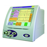
SLE SLE4000 Model B User Manual (292 pages)
Infant Ventilator
Brand:
SLE
| Category:
Fan
| Size: 5 MB
Table of Contents
Table of Contents
5
1 Introduction
14
About this Manual
14
Intended Use
14
Intended Users
14
2 Description of the Ventilation Modes
15
Cpap
15
CPAP with Apnoea Backup
15
CPAP with TTV (Targeted Tidal Volume) for Back up Breaths
15
CMV
16
CMV with TTV
16
Ptv
17
PTV with TTV
18
Psv
19
PSV with TTV
20
SIMV (Synchronized Intermittent Mandatory Ventilation)
21
SIMV with PSV
22
SIMV with TTV
23
HFO (SLE5000 Only)
23
HFO+CMV (SLE5000 Only)
23
Mode Controls
24
TTV Control Mode
24
Technical Description
25
3 User/Owner Responsibility
26
4 Warnings
28
Operational Warnings
28
Clinical Warnings
31
5 Ventilator Description
34
6 Description of Symbols and Buttons
37
7 User Interface
44
User Interface Sections
44
Description of User Interface Indicators
45
Description of User Interface Controls
45
Examples of Control Use
46
Description of the Mode Panel in Ventilation off Mode
48
Mode Panel in Ventilation off Mode
48
Mode Select Button
48
Oxygen Alarm Test
49
Services Panel
49
Flow
50
Oxygen
50
Wave Shaping
50
Alarm Volume
51
More Options Panel
51
Language Toggle
52
Version Information Panel
53
Monitor Services
54
Controller Services
54
Mode Panel Functions in a Ventilation Mode
55
Standby Button (All Modes)
55
Apnoea Setup for CPAP
56
Apnoea Setup for PTV, PSV and SIMV
56
TTV for CPAP, PSV, PTV & SIMV
57
Set Trigger for CPAP, PSV, PTV & SIMV
57
Pressure Support in PSV
57
Pressure Support in SIMV
58
HFO Activity (SLE5000 Only)
58
Alarm Panel
59
Default Waveform Windows
60
Alarm and Breath Detection Thresholds
62
How to Set an Alarm Threshold
63
Ventilation Parameters
66
Lung Mechanics and Measurement Panel
68
The Pause Button
70
Night Button and Screen Lock
70
8 Loops, Trends & Waveforms
72
Waveforms
72
Loops
74
Storing and Retrieving Loops
74
Trends
76
Description of Trend Windows
76
9 Ventilator Set-Up
78
Preparing the Ventilator for Use
78
Setup Related Items
82
Shutting down of the Ventilator
82
Back-Up Battery Charging
82
10 Quick Setup
84
Complete Power Fail Alarm Test
85
Calibration of the Flow Sensor
86
Low Oxygen Alarm Test
87
Apnoea Alarm
89
Leak / Block Alarm
90
High Pressure Alarm
90
Low Tidal Volume
90
Functional Test of HFO+CMV Mode
91
11 Functional Testing
94
Stage 1 Functional Testing
95
Complete Power Fail Alarm Test
95
Setting Fio
96
Functional Testing with no Flow Sensor
96
Calibration of the Flow Sensor
96
Oxygen Alarm Test
98
Function and Alarm Testing
100
High Pressure Alarm
104
Low Alarm
104
Breath Not Detected Alarm
105
Leak / Block Alarm
106
Mains Failure Alarm
106
Gas Supply Alarms
107
Flow Sensor Disconnect Alarm
108
Cycle Fail Alarm
108
Functional Test of HFO Mode
110
Functional Test of HFO+CMV Mode
112
Pressure Change Alarm
114
Stage 2 Functional Testing
115
Functional Test of CMV Mode
115
Functional Test of PSV Mode
120
Functional Test of SIMV Mode
123
12 Stage 1 Check List
129
13 Stage 2 Check List
131
14 Operational Considerations
134
General
134
Ventilation off Mode
134
Gas Input Pressures
134
Mode Memory on Power up
134
Back up Battery Power
134
Parameter Memory
135
BPM or Backup, Measured and Set Parameters
135
Tidal Volume Parameter Resolution
135
HFO, Mean and Delta P Parameters
135
Displayed Fio
135
Breath Detection
136
Max Ti in PSV
136
TTV (Targeted Tidal Volume)
136
Overshoot
137
Wave Shaping
137
Circuit Disconnection Procedure
138
BPM Tot. Measurement
139
Alarms
140
High and Low Alarm Operation
140
Minute Volume Alarm Threshold
141
Cycle Fail Alarm Threshold
141
Sub-Ambient Pressure Alarm in Non HFO Modes
141
HFO Only Ventilator Set Threshold Alarms (SLE5000 Only)
142
Patient Leak Alarm
143
Reset Contamination Alarm
143
Patient Circuits, Humidification and Nitric Oxide Therapy
144
Patient Circuits with Incubators, Cots and Paediatric Beds
144
Autofeed Humidification Chambers
145
Nitric Oxide Therapy
146
Nebulization of Medication
147
15 Flow and Pressure Triggering
150
Breath Detection Threshold (Flow Triggering)
150
Breath Trigger Sensitivity (Pressure Triggering)
151
Setting the Pressure Trigger Level in CPAP, SIMV, PTV and PSV
152
16 Basic Set-Up
154
Pre Set-Up Checks
154
Setting the Fio
155
CPAP Set-Up
156
Actions after Connection to Patient in CPAP
157
Ventilation Without a Flow Sensor Connected
159
CMV Set-Up
160
Actions after Connection to Patient in CMV
161
Ventilation Without a Flow Sensor Connected
162
PTV Set-Up
163
Actions after Connection to Patient in PTV
164
Ventilation Without a Flow Sensor Connected
166
PSV Set-Up
167
Actions after Connection to Patient in PSV
168
Ventilation Without a Flow Sensor Connected
170
SIMV Set-Up
171
Actions after Connection to Patient in SIMV
172
Ventilation Without a Flow Sensor Connected
175
HFO Only Set-Up (SLE5000 Only)
176
Actions after Connection to Patient in HFO
177
Ventilation Without a Flow Sensor Connected
177
HFO+CMV Set-Up (SLE5000 Only)
178
Actions after Connection to Patient in HFO+CMV
179
Ventilation Without a Flow Sensor Connected
179
17 N5201 Flow Sensor
182
Calibration of the Flow Sensor
182
Cleaning and Sterilization
184
18 Frequently Asked Questions
188
Ventilator Related Questions
188
What Range of Patients Is the Ventilator Designed to Ventilate
188
Can the Ventilator be Used Without a Flow Sensor
188
How Often Must the Flow Sensor be Calibrated
188
What Does "SENSOR CONTAMINATION" Mean
188
What Is Standby Mode Used for
188
What Happens When the Pause Button Is Pressed
189
What Is the Operating Time of the Battery
189
What Is the Battery Charging Time
189
What Is the Difference between PTV and PSV
189
When Looking at the Parameter Settings, What Do I Record
189
Where Do I Set the Trigger Sensitivity
189
Mode Related Questions
190
What Is Meant by Targeted Tidal Volume
190
What Are Appropriate Tidal Volumes
190
What Is the Meaning of Compliance and Resistance
190
How Do I Minimise the Apnoea Alarm in CPAP
190
In TTV some of the Breaths Exceed the Set TTV. Why
190
Why Is There no SET Value for MAP and Dp in HFO Mode
191
Patient Circuits
191
What Is the Difference between the N2188 and N5188 Patient Circuit
191
Why Is a Restrictor Necessary
191
What Is a /02 Patient Circuit
191
What Is a /850 Patient Circuit
191
What Happens if the Restrictor Is Placed in the Expiratory Limb Instead of the Inspiratory Limb
191
Should Bacterial Filters be Used on the Expiratory Limb
191
When Using the INOSYS Nitric Oxide Therapy and the Ventilator What Scavenging Filters Do I Need
191
How Often Does the Exhalation Block and Silencer Need to be Autoclaved
192
How Do I Clean the Exhalation Block and Scavenging System after Using no
192
19 Commonly Seen Alarms
194
High Pressure Alarm
194
Low Pressure Alarm
194
Breath Not Detected
194
Low Tidal Volume
194
Unexpected Rise or Drop in Mean P (SLE5000 Only)
195
Unexpected Rise or Drop in Max P (SLE5000 Only)
195
Unexpected Rise or Drop in Min P (SLE5000 Only)
195
Continuing Positive Pressure
195
Leaking Fresh Gas
195
High Patient Leak
196
Clean Flow Sensor
196
Faulty Flow Sensor
196
Calibration Fail
197
Calibrate Flow Sensor
197
Apnoea (Volume)
197
Trouble Shooting Chart
199
20 Trouble Shooting Chart
200
Ventilator Related Problems
200
Ventilation Related Problems
209
Technical Information
213
21 Oxygen Calibration Routines
214
One Point O Calibration
214
Two Point O Calibration
214
22 Preventative Maintenance and Overhaul Schedule
215
23 Rs232
216
Warnings for RS232
216
Location of RS232 Port
216
Overview
217
Data and Pinout Description
217
Cable
217
Parameter Descriptions and Format
218
List of Parameters
218
Table of Current Alarm Condition Codes
221
RS232 Connection Settings and Testing Data Output
223
24 Alarms
224
Alarm Protocols
224
Alarm Sounds
224
Alarm Descriptions and Actions to be Taken
225
Software and System Fail Protocols
244
25 Bacterial Filters
245
Bacterial Filter, SLE Part Nº:N2029 (Autoclavable)
245
Bacterial Filter, SLE Part Nº: N2587 (Single Use)
246
Precautions When Using Bacterial Filter N2587
246
26 Patient Circuits
247
Warnings for Patient Circuit Use
247
10Mm Diameter Re-Usable Patient Circuit (SLE Part Nº N2391/50)
248
Sterilising of the N2391/50 Re-Usable Patient Circuit
248
10Mm Patient Circuit, SLE Part Nº N5188 & N5188/850
250
10Mm Patient Circuit, SLE Part Nº N5188/02 & N5188/02/850
252
N5238/50 Heated Patient Circuit for no Therapy
254
Nitric Oxide Delivery Adaptor Kit (SLE Part Nº N2238/50)
256
27 Cleaning, Disinfection and Sterilization
257
Preparation of a New Ventilator
257
Cleaning and Disinfection of an In-Service Ventilator
257
Cleaning, Disinfection & Sterilization Chart
258
Cleaning Method
258
Disinfection Method
259
Sterilization Method
260
28 Technical Specification
261
Operating Modes Conventional Ventilation
261
Cpap
261
CMV
261
Ptv
261
Psv
262
Simv
262
HFO Ventilation
262
HFO Only
262
Hfo+CMV
262
Controls (Via Touch Screen Display)
263
Controls
266
Measurement
266
Flow and Volume
266
Oxygen Concentration
266
Pressure
267
Alarms
268
User Settable Alarms
268
Obligatory Alarms (Non Adjustable by User)
269
Patient Circuits
269
Outputs
270
Gas Supplies
271
Oxygen Supply
271
Air Supply
271
Flows
271
Power, Dimensions, Standards Etc
272
Environmental Storage Conditions
272
29 Pneumatic Unit Schematic
273
30 Ventilator Labelling
274
Sle4000
274
Sle5000
275
31 Consumables and Accessories
278
32 Glossary of Abbreviations Used in this Manual
284
33 Index
287
Advertisement
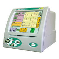
SLE SLE4000 Model B Service Manual (312 pages)
Infant Ventilator with Touch-Screen Model K
Brand:
SLE
| Category:
Fan
| Size: 9 MB
Table of Contents
Table of Contents
3
Warnings and Cautions
7
1 Warnings and Cautions
8
Warnings
8
Cautions
9
2 Principles of Operation
12
Electronic System
12
Pneumatic System
13
Description of Symbols
15
3 Description of Symbols
16
4 Equipment List
20
5 Engmode
22
Accessing the Calibration Programs
22
Ventilator Calibration Program
24
O 2 & Flow System Calibration
25
Reset Elapsed Time
26
Language Selection
26
Activation of Language Selection Program Form User Interface
27
Exit
27
Touch Screen Calibration Program
28
6 Component Replacement Procedure
30
7 Preparing the SLE4000
31
8 Component Replacement (Electronic Unit)
33
N6631/21/CF/50 Compact Flash Card
33
N6631/LX800 PC Board
33
N6634/OEM2 CAN Card
34
N6631/2216 Serial Controller (Touch Screen)
34
L0275/OEM2 Computer/Display Control Assembly
35
A0763/4B Control/Monitor Board
36
M0915 Power Supply Unit
37
M0901 Batteries
38
A0761 Transducer PCB Assembly
39
N6631/13 Inverter PCB
40
N6631/02 LCD & N6631/05 Touch Screen
41
9 Component Replacement (Pneumatic Unit)
43
Duckbill and Conical Filters
43
10 A0763/4B Monitor and Control Board
52
A0763/4B Board Progammable Devices
52
A0763/4B Board Hardware Identifier
53
11 Electrical Safety Testing of the SLE4000
57
12 PSU Testing
61
13 Ventilator Power up and Power down
64
14 Back-Up Battery Charging
65
Battery Indicator
65
15 Extended Storage
67
16 Maintenance and Overhaul
70
Preventative Maintenance Kit
70
36 Month Preventative Maintenance Procedure
72
Month and 48 Month Overhaul Procedures
80
Month / 10,000 Hour Overhaul Procedure
82
Month / 20,000 Hour Overhaul Procedure
90
Month Overhaul Procedure Using N9410/48/G Overhaul Kit
92
17 Calibration Procedure for V4.3.1 & V4.3.2 Software
96
Equipment Required for Calibration
96
Preliminary Inspection before Calibration
96
Pneumatic Set up
97
Calibration of Controller and Monitor Subsystems
100
Controller "Block and Leak" Pressure Sensor Calibration
102
Controller Blender Pressure Sensor Zeroing and Input Pressure Reg. Trim
103
Mean Jet Pressure Regulator Calibration
104
Forward Jet Pressure Regulator Calibration
106
Wave Shaping for Leading and Trailing Edge of Insp. Phase
107
O 2 System Calibration
108
Flow System Calibration
108
Pressure Triggering Verification
108
Gas Fail Detection Verification
109
Blender and Oxygen Monitoring Verification
110
Soak Test
111
Battery Charge Verification
111
Total Power Fail Alarm Test
111
Pressure Calibration Verification
112
18 Functional Testing
114
Ventilator Setup
114
Trouble Shooting
141
19 Trouble Shooting Chart
142
20 Software Version History
152
Technical Information
153
21 Oxygen Calibration Routines
154
One Point or 100% Oxygen System Calibration
154
Two Point or 21% & 100% Oxygen System Calibration
154
22 Alarms
156
Alarm Protocols
156
Alarm Sounds
156
Alarm Descriptions and Actions to be Taken
157
Software and System Fail Protocols
176
23 Cleaning, Disinfection and Sterilization
177
Preparation of a New Ventilator
177
Cleaning and Disinfection of an In-Service Ventilator
177
Cleaning Method
178
Disinfection Method
179
Sterilization Method
180
24 Technical Specification
181
Operating Modes Conventional Ventilation
181
Exhalation Block Port Jet Sizes
182
Measurement
186
Alarms
187
Patient Circuits
188
Outputs
189
Gas Supplies
190
Power, Dimensions, Classification Etc
191
Classification
191
Environmental Storage Conditions
191
25 EMC Compliance
192
Electromagnetic Immunity
193
Recommended Separation Distances between Portable and Mobile RF Communications Equipment and the SLE4000
195
26 Ventilator Labelling
196
Sle4000
196
27 Electrical Block Diagram
198
28 L0288/KV Pneumatic Unit Layout & Schematic
199
Layout
199
Schematic
200
29 Main Loom Circuit Diagram
201
30 L0275/OEM2 Assembly Schematic
202
31 A0761 Circuit Diagram
204
Transducer PCB Assembly
204
32 A0763/4B Circuit Diagrams
206
Micro Controller
206
Conventional Valve Drive
207
Power Distribution and Hardware Identifier
208
Analogue Valve Drive / Non Volatile Memory / Interboard Comms
209
High Speed Valve Drive
210
Analogue Data Acquisition/Monitor Port
211
Control & Monitor, PCB PSU Circuit
212
Control & Monitor, Micro Non-Isolated
213
Control & Monitor, Micro Isolated
214
Control & Monitor, Analog Isolated
215
Control & Monitor, Alarm Controller
216
33 Illustrated Parts List
218
Ventilator Assembly
220
Base Plate and Side Door Assembly
227
Front Facia Assembly
229
Electronic Module
231
Pneumatic Module
252
DISS Air and Oxygen Fittings
264
34 Equipotential Stud Modification
268
Equipotential Stud Connection
269
Appendix 1. Calibration Checklist
273
Appendix 2. Check List
281
Appendix 3. TB & si Index
286
35 Technical Bulletin & Service Information Letters
286
Service Information Letters
286
Technical Bulletins
288
Appendix 4
290
Overview
291
Data and Pinout Description
291
Cable
291
Parameter Descriptions and Format
292
List of Parameters
292
Table of Current Alarm Condition Codes
295
RS232 Connection Settings and Testing Data Output
297
Glossary
297
36 Rs232
290
Warnings for RS232
290
Location of RS232 Port
290
Appendix 5. Vuelink
300
37 Vuelink Technical Data
300
Glossary
300
Connecting the SLE4000 to the Vuelink Patient Monitor
300
Parameter Descriptions
301
Data Transferred to the Vuelink System from the SLE4000
302
Alarm and Inoperative Indications
304
Vuelink Task Window Layout
307
Notes on General System Behaviour
308
Activation of Vuelink
309
Disabling Vuelink
310
SLE SLE4000 Model B Service Manual (329 pages)
Model C
Brand:
SLE
| Category:
Fan
| Size: 13 MB
Table of Contents
Warnings and Cautions
7
Warnings and Cautions
8
Cautions
9
Principles of Operation
12
Pneumatic System
13
Description of Symbols
15
Description of Symbols
16
Equipment List
20
Engmode
22
Ventilator Calibration Program
24
Reset Elapsed Time
26
Activation of Language Selection Program Form User Interface
27
Touch Screen Calibration Program
28
Component Replacement Procedure
30
Preparing the SLE4000
31
Component Replacement (Electronic Unit)
33
N6634 CAN Card
34
L0275 Computer/Display Control Assembly
35
A0763/4B Control/Monitor Board
36
M0900 Power Supply Unit
37
M0901 Batteries
38
A0761 Transducer PCB Assembly
39
N6631/13 Inverter PCB
40
N6631/02 LCD & N6631/05 Touch Screen
41
Component Replacement (Pneumatic Unit)
43
L0287 Blender Assembly
44
N2195/06 SV7 Fresh Gas Supply Solenoid
45
N6612 FR7 Flow Regulator
46
N6615/01 PR1 Input Air Regulator
47
N6615/02 PR2 Input Oxygen Regulator
49
L0289 Pressure Regulator Module
52
N2181 PR5 Regulator
54
N6623/S38 PR4 & PR6 Pressure Regulators
55
N2195/16 SV13 Solenoid
57
A0763/4B Monitor and Control Board
60
A0763/4B Board Hardware Identifier
61
Electrical Safety Testing of the SLE4000
65
PSU Testing
69
Maintenance and Overhaul
72
Month Preventative Maintenance Procedure
74
Month and 48 Month Overhaul Procedures
82
Month / 10,000 Hour Overhaul Procedure
84
Month / 20,000 Hour Overhaul Procedure
91
Month Overhaul Procedure Using N9410/48 Overhaul Kit
93
Calibration Procedure for V4.1 to 4.3.2 Software
104
Pneumatic Set up
105
Calibration of Controller and Monitor Subsystems
106
Controller "Block and Leak" Pressure Sensor Calibration
108
Mean Jet Pressure Regulator Calibration
110
Forward Jet Pressure Regulator Calibration
111
Wave Shaping for Leading and Trailing Edge of Insp. Phase
112
Flow System Calibration
113
Gas Fail Detection Verification
114
Blender and Oxygen Monitoring Verification
115
Soak Test
116
Battery Charge Verification
117
Pressure Calibration Verification
118
Functional Testing
120
Trouble Shooting
147
Trouble Shooting Chart
148
Software Version History
156
Technical Information
157
Oxygen Calibration Routines
158
Alarms
160
Alarm Descriptions and Actions to be Taken
161
Software and System Fail Protocols
180
Cleaning, Disinfection and Sterilization
181
Cleaning Method
182
Disinfection Method
183
Sterilization Method
184
Technical Specification
185
Measurement
190
Exhalation Block Port Jet Sizes
191
Alarms
192
Patient Circuits
193
Outputs
194
Gas Supplies
195
Power, Dimensions, Standards Etc
196
Ventilator Labelling
197
Electrical Block Diagram
200
L0288 Pneumatic Unit Layout
201
Pneumatic Unit Schematic
202
Pneumatic Unit Tubing Connections
203
Main Loom Circuit Diagram
204
A0761 Circuit Diagram
206
A0763/02 Circuit Diagrams
208
Conventional Valve Drive
209
Power Distribution and Hardware Identifier
210
Analogue Valve Drive / Non Volatile Memory / Interboard Comms
211
High Speed Valve Drive
212
Analogue Data Acquisition/Monitor Port
213
Control & Monitor, PCB PSU Circuit
214
Control & Monitor, Micro Non-Isolated
215
Control & Monitor, Micro Isolated
216
Control & Monitor, Analog Isolated
217
Control & Monitor, Alarm Controller
218
Illustrated Parts List
220
Ventilator Assembly
222
Base Plate and Side Door Assembly
229
Front Facia Assembly
231
Electronic Module
233
Pneumatic Module
253
Pressure Regulator Module
260
Oxygen Regulator Module
268
Partition Assembly
271
Pneumatic Module, Sub Assembly
275
Equipotential Stud Modification
284
Equipotential Stud Connection
285
Appendix 1. Calibration Checklist
289
Appendix 2. Check List
297
Appendix 3. TB & si Index
302
Technical Bulletins
304
Appendix 4. RS232
306
Overview
307
Parameter Descriptions and Format
308
Table of Current Alarm Condition Codes
311
RS232 Connection Settings and Testing Data Output
313
Appendix 5. Vuelink
316
Parameter Descriptions
317
Data Transferred to the Vuelink System from the SLE4000
318
Alarm and Inoperative Indications
320
Vuelink Task Window Layout
323
Notes on General System Behaviour
324
Activation of Vuelink
325
Disabling Vuelink
326
Advertisement
Advertisement
Related Products
SLE SLE2000 HFO
SLE SLE5000 Model J
SLE SLE1000
SLE 2000 HFO
SLE 2000 HFO+
SLE Categories
Fan
Medical Equipment
Home Lighting
Air Compressor
Printer
More SLE Manuals
Login
Sign In
OR
Sign in with Facebook
Sign in with Google
Upload manual
Upload from disk
Upload from URL