
Related Manuals for SLE 2000 HFO


Summary of Contents for SLE 2000 HFO
- Page 1 SLE 2000 HFO Ventilator User manual High Frequency Oscillatory Ventilator 0120 Issue...
- Page 2 All rights reserved. No part of this publication may be reproduced, stored in any retrieval system, or transmitted in any form or by any means, electronic, mechanical, photocopy, recording or otherwise, without prior permission of SLE. © Copyright SLE 01/10/2004. Manual : UM0008 Issue 13 SLE Part Nº:...
-
Page 3: Table Of Contents
7.2. To Use the SLE 2000 HFO in CMV Mode .......... 28 7.3. Patient Trigger Modes ................ 29 7.3.1. To Use SLE 2000 In PTV or SIMV Mode........29 7.4. To Use the SLE 2000 HFO in the Oscillator Mode ......30 Technical information 8. Ventilator Controls ..................34 8.1. - Page 4 12. Patient Circuit Connection ............... 47 13. Filter Systems .................... 49 13.1. Bacterial filter, SLE Part Nº:N2029 (Autoclavable) ......49 13.2. Bacterial filter, SLE Part Nº:N2587 (Single use) ....... 49 13.2.1. Precautions when using bacterial filter N2587 ......49 Page 4 of 70...
- Page 5 20.6.2. Air supply ................... 63 20.7. Power , Dimensions etc..............64 20.8. Environmental Storage Conditions ........... 64 21. Consumables and Accessories for SLE 2000 HFO ........ 65 22. Ordering Information for the SLE2000 HFO ........... 67 22.0.1. Options..................67 22.0.2.
- Page 6 This page is intentionally blank. Page 6 of 70...
- Page 7 How to use the SLE2000 HFO NOTE THE WARNINGS (PAGE 12) MUST BE READ AND UNDERSTOOD BEFORE USING THE SLE2000 HFO VENTILATOR. FAILURE TO DO SO COULD LEAD TO INJURY OR DEATH 1 PERFORM THE FUNCTIONAL TESTS : PAGE 18 (THIS SHOULD TAKE NO MORE THAN 20 MINUTES) 2 SETUP THE SLE2000 HFO IN THE CHOSEN MODE: PAGE 25 3 THE SLE2000 HFO IS READY FOR USE...
-
Page 8: Introduction
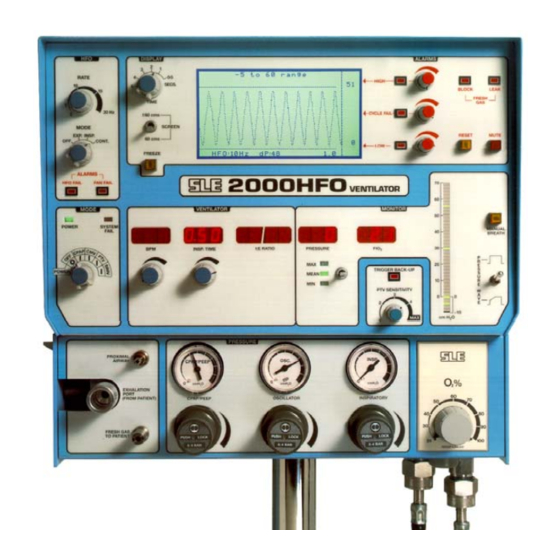
1. Introduction The SLE2000 HFO ventilator is designed for use on neonates/infants. Its principle of operation is time cycled, pressure limited ventilation using a constant fresh gas flow. Main features are that it has no expiratory valve but uses a reverse flow of mixed gas that is injected into the expiratory limb of the patient circuit from the exhaust manifold. -
Page 9: Principles Of Operation Sle 2000 Hfo
1.1 Principles of Operation SLE 2000 HFO The patient circuit is supplied with a constant fixed flow of fresh gas at 5 litres per minute. This gas comes from the internally mounted Oxygen Blender and its concentration is monitored by a fuel cell and displayed on the FlO digital display. - Page 10 The same gas mixture from the Oxygen Blender is used to supply the patient Fresh Gas, CPAP, Inspiratory and Oscillation driving gas pressure. This avoids any possibility of dilution of the Fresh Gas mixture. There is a wave shape switch. This modifies the Driving Gas flow rate from the Solenoid valve through the nozzle and is used to slow down the rise time of the pressure waveform.
-
Page 11: User/Owner Responsibility
SLE, or parts which are otherwise approved by SLE. Equipment which is not functioning correctly or is... -
Page 12: Warnings
The ventilator functional tests must be carried out each time the SLE 2000 HFO is used on patients. If any of these tests do not function as described then there is a problem and the ventilator must not be used until it is rectified. -
Page 13: Clinical Warnings
No external voltage should be applied to the auxiliary socket. Any connections to this socket must be approved by SLE and screened to comply with EMC regulations. Ensure protection cap is fitted when socket is not in use. - Page 14 Maintenance of an adequate airway is paramount in the infant or child undergoing high-frequency oscillatory ventilation. The following points should be stressed in airway management on units employing HFOV: The largest endotracheal tube should be used which is compatible with a close, but not tight, fit in the larynx;...
-
Page 15: Glossary Of Abbreviations Used In This Manual
4. Glossary of Abbreviations Used in This Manual Unit of Barometric Pressure Kilogram Breaths Per Minute Light Emitting Diode Centimetre Low Frequency Centimetres of Water Litres per Minute Centimetres of Water Maximum Inspiratory Time Controlled Mechanical Ventilation Millilitres CPAP Continuous Positive Airway Pressure Millisecond °C Degrees Celsius... -
Page 16: Symbols
5. Symbols The Following Symbols are used on the Equipment Alternating Current Attention, consult accompanying documents. Conformance mark and notified body registration 0120 Type B (IEC601-1) protection against electric shock. On (power: connection to the mains) Off (power: disconnected from the mains) Rotate: clockwise to increase, anticlockwise to decrease Page 16 of 70... -
Page 17: Operating Instructions
Operating Instructions Page 17 of 70... -
Page 18: Sle 2000 Hfo Functional Tests
4 bar. Connect mains cable to a suitably rated and grounded electrical power source. Step 2. Connect SLE approved patient circuit with test lung to the ventilator. • For further information see page 47 or instructions supplied with patient circuit. -
Page 19: Automatic Power On Test
Operating Instructions 6.2 Automatic Power On Test Select ventilator mode to CPAP. The ventilator will now carry out a self test as follows. Power LED shows green and an automatic test of functions & alarms is initialised. Firstly the displays and audible alarms are turned on for approximately two seconds to demonstrate that they are operable, then for a further three seconds all the digital displays show a sequence of numbers from O to 9 before returning to their normal state. -
Page 20: Cmv Mode
Operating Instructions 6.5 CMV Mode Step 1. Set the following ventilator conditions :- • CPAP/PEEP regulator to 0 cmH Inspiratory regulator to ≈ 30 cmH • • Mode switch to CMV • BPM Rate to 60 • INSP TIME to 0.50 •... -
Page 21: Simv Mode
Operating Instructions 6.7 SIMV Mode Select SIMV with mode switch. Ensure that:- • The ventilator continues to cycle. • The BPM display shows set rate. • The TRIGGER BACK-UP LED illuminates on each inspiration. Apply a varying pressure to test lung to simulate patient breathing. Ensure that:- •... - Page 22 Operating Instructions Set HFO mode to INSP Ensure that :- • 10 Hz oscillation shown on inspiratory cycle of waveform. Set HFO mode to CONT Ensure that :- • 10 Hz oscillation shown on both inspiratory and expiratory cycles of waveform. Set mode switch to CPAP.
-
Page 23: Alarm Test
Operating Instructions 6.9 Alarm Test 6.9.1 To Verify Alarms Set the following ventilator conditions :- • HFO mode OFF. CPAP/PEEP regulator to ≈10 cmH • Inspiratory regulator to ≈30 cmH • • Oscillator Regulator to 0 cmH • Mode switch to CMV •... -
Page 24: Leak/Block Alarm
Operating Instructions 6.9.5 Leak/block Alarm Disconnect the fresh gas tubing from the ventilator. This should initiate an audible and LEAK visual alarm indication. Occlude the fresh gas outlet. This should initiate an audible and BLOCK visual alarm indication. Reconnect tubing, audible and visual alarms should self reset. -
Page 25: Basic Set Up For The Sle 2000 Hfo
4 bar. Connect mains cable to a suitably rated and grounded electrical power source. Step 2. Connect SLE approved patient circuit to the Ventilator and Humidifier. • For further information see page 47 or instructions supplied with patient circuit. - Page 26 Operating Instructions Do not continue until alarms are cleared • The ranges of the graphic display can be set using the display controls. A FREEZE button allows the waveform to be held. Press to freeze, press again to un-freeze. • Do not carry out any adjustments with the display in the freeze mode.
-
Page 27: To Use The Sle 2000 Hfo In Cpap Mode
Operating Instructions 7.1 To Use the SLE 2000 HFO in CPAP Mode As steps 1 to 6 in basic set-up Step 7. (a) Set pressure display switch to minimum (b) Increase CPAP/PEEP pressure to required level These Controls are lockable. Push to lock, Pull to unlock. -
Page 28: To Use The Sle 2000 Hfo In Cmv Mode
Operating Instructions 7.2 To Use the SLE 2000 HFO in CMV Mode As steps 1 to 7 basic set-up and CPAP then:- Step 8. (a) Set INSP. TIME to required rate (displayed in seconds) (b) Select Pressure Wave Shape SQUARE or TAPER... -
Page 29: Patient Trigger Modes
Operating Instructions 7.3 Patient Trigger Modes 7.3.1 To Use SLE 2000 In PTV or SIMV Mode As steps 1 to 7 then:- Step 9. (a) Set PTV sensitivity to min (b) Set the BPM control to provide either:- The desired back-up rate for PTV... -
Page 30: To Use The Sle 2000 Hfo In The Oscillator Mode
Operating Instructions 7.4 To Use the SLE 2000 HFO in the Oscillator Mode THERE ARE 4 OSCILLATORY MODES 1 EXP. Expiratory oscillation combined with conventional ventilation. (a) Set ventilator mode to CMV (see page 28) (b) Set HFO mode to EXP (c) Set HFO frequency using rate control. - Page 31 Operating Instructions 3 CONT. (combined) Insp+Exp oscillation combined with conventional ventilation. (a) Set ventilator mode to CMV (see page 28) (b) Set HFO mode to CONT (c) Set HFO frequency using rate control (d) Set amplitude using oscillation pressure regulator •...
- Page 32 Operating Instructions This page is intentionally blank. Page 32 of 70...
- Page 33 Technical Information Page 33 of 70...
-
Page 34: Ventilator Controls
Technical Information 8. Ventilator Controls 8.1 Electronic Module 8.1.1 Mode Switch (5 positions) OFF- CPAP- CMV- PTV- SIMV • OFF = All electrical power off. Note: There is a limited fresh gas supply with mode switch in the OFF position, if ventilator is used with Head boxes etc. switch to CPAP. -
Page 35: Ptv Mode
Technical Information 8.1.5 PTV Mode BPM control no longer functions in this mode. The last BPM setting in CMV, prior to switching to PTV will be the back-up rate. (Setting a time window for Apnea). Additionally the PTV sensitivity control is activated, all inspiratory efforts at chosen sensitivity should trigger the ventilator. - Page 36 Technical Information The SIMV mode of the SLE 2000HFO functions in the following manner: The BPM control setting will determine the number of breaths that will be supplied in each minute. In the period between each of these breaths a time window is opened.
-
Page 37: Bpm
Technical Information 8.1.7 BPM Ten-turn control with LED digital indication to set the breath rate per minute. 8.1.8 Inspiration Time Set by ten-turn control with indication on 3 digit LED display showing the set value in seconds. Invalid settings of the BPM. and INSP. TIME controls are indicated by these two displays flashing. -
Page 38: Pressure Display Bargraph
Technical Information 8.1.13 Pressure Display Bargraph. Shows pressure and selected alarm settings -10 to +70 cms 8.1.14 Pressure Wave Switch This switch alters the pressure waveform from SQUARE to TAPERED as indicated. • This is an Automatic Locking Toggle Switch. Pull toggle lever to release. •... -
Page 39: Hfo Controls
Technical Information 8.1.16 HFO Controls Mode. Four positions. OFF - EXP- INSP - CONT Oscillation is provided on the expiratory, inspiratory and expiratory/inspiratory parts of the pressure wave. Continuous oscillation can also be provided by selecting CONT on the HFO mode control and CPAP on the MODE control. Rate Controls the frequency of HFO oscillation in Hertz. -
Page 40: Pneumatic Module
Technical Information 8.2 Pneumatic Module 8.2.1 Proximal Airway Input from patient ET connector to pressure display bargraph and internal pressure transducers. 8.2.2 Removable Exhalation Block Can be removed easily for cleaning by lowering side panel. PRESSURE RELIEF VALVE 8.2.3 Fresh Gas Port The Fresh Gas port supplies 5 LPM of the blended gas via the humidifier to the patient inspiratory port on the ET connector. -
Page 41: Regulator And Pressure Gauges
Technical Information 8.2.4 Regulator and Pressure Gauges 8.2.4.1 CPAP This regulator controls the base pressure in the circuit. In HFO mode this control will be used to set the mean pressure. 8.2.4.2 Oscillator This regulator controls the amplitude of the oscillatory pressure. -
Page 42: Alarms
Technical Information 9. Alarms Warning Audible and Visual warning alarms indicate a potentially harmful condition to the patient. Failure to take corrective action could result in injury or death to the patient. 9.0.1 Microprocessor The microprocessor system failure and other electronic circuitry failures are alarmed as follows. -
Page 43: Fresh Gas Fail Alarm (Block & Leak)
Technical Information 9.0.4 Fresh Gas Fail Alarm (Block & Leak) This fresh gas failure system will detect either a blockage or a leak in the Fresh Gas supply line.To achieve this there is a small restrictor fitted in the inspiratory limb of the patient circuit, creating a pressure in the alarm circuitry to the Electronics Module. -
Page 44: Cycle Fail Alarm
Technical Information 9.0.9 Cycle Fail Alarm This alarm will be activated should the pressure wave fail to pass through the CYCLE FAIL alarm setting on either inspiration or expiration, indicating a drop in airway pressure, a leak or circuit blockage. The audible alarm will reset automatically on correct pressure being restored but the visual alarm must be RESET by pressing the reset button. -
Page 45: Auxiliary Output
10. Auxiliary Output Warning No external voltage should be applied to the auxiliary socket. Any connections to this socket must be approved by SLE and screened to comply with EMC regulations. Ensure protection cap is fitted when socket is not in use. -
Page 46: Rear Panel
Technical Information 11. Rear Panel 232 SELSDON ROAD SOUTH CROYDON SURREY CR2 6PL U.K. Auxiliary Output Connector TYPE Nº SERIAL Nº 100% Adjustment SUPPY V ~ Hz POWER A CLASS TYPE FuseHolders 100% Adjustment Tool Fan Filter Fan Filter Alarm Sounder Mains Cable Running Time indicator Fan Filter... -
Page 47: Patient Circuit Connection
RE-USABLE PATIENT CIRCUIT (SLE Part Nº N2391) This circuit must be clean and sterilised before use. It is designed to be used with an SLE 2000 or SLE2000HFO Infant Ventilator in combination with a Servo controlled humidifier- typically a Fisher and Paykel or equivalent. - Page 48 - typically SLE3000, Fisher and Paykel or equivalent. DIRECTIONS FOR USE CAUTIONS It is recommended that a high quality bacteria filter (SLE part • Make sure that all connections are made properly and No. N2029) is fitted at the fresh gas connection to the are tight before use.
-
Page 49: Filter Systems
12 months. For other makes of bacterial filter please refer to manufacturers instructions. 13.2 Bacterial filter, SLE Part Nº:N2587 (Single use) This single use bacterial filter is fitted onto the exhalation block outlet. This filter should be disposed of in accordance with local hospital authority guidelines. A new filter should be used for every new patient. -
Page 50: Cleaning, Disinfection And Sterilization
DO NOT steam autoclave the SLE 2000 HFO or otherwise subject it to temperatures above 62°C. DO NOT immerse any part of the SLE 2000 HFO in any liquid, with the exception of the expiratory exhalation block (SLE part No N0635). -
Page 51: Cleaning, Disinfection & Sterilization Chart
Technical Information • Lift up lever (A) on side of ventilator and lower side flap. • Remove the silencer (B) by pulling it through the hole at the rear. • Remove the exhalation block (C) by firstly taking hold of the block and then pulling it out towards you without the need for undue force. -
Page 52: Disinfection Method
14.5 Sterilization method The silencer SLE part Nº N2186 and exhalation block SLE part Nº N0635 must be sterilized between use on patients. The ventilator cannot be sterilized. The exhalation block must be cleaned as an essential prerequisite to sterilization. -
Page 53: Service And Maintenance Programmes
Technical Information 15. Service and Maintenance Programmes Service or calibration of this ventilator should only be carried out by an SLE trained hospital engineer or an SLE service engineer. 15.1 Maintenance 6 Month Preventative Maintenance Preventative maintenance should be performed at 6 monthly intervals. This maintenance is intended to be carried out in the hospital. -
Page 54: User Operational Checks
The filters are accessed by pulling the fan covers off. • Two on the back panel and one on the side panel • SLE part no M0701/04 3. Check the running time meter on the rear of the ventilator to see if preventative maintenance or overhaul is due. -
Page 55: Sle 2000 Hfo Trouble Shooting Chart
Technical Information 17. SLE 2000 HFO Trouble Shooting Chart Symptom Possible Cause Remedy Leak Alarm - audible Incorrect circuit fitted. Replace with correct circuit & visual P/No. N2188 or variant. Replace with new circuit. Damaged circuit fitted. Replace chamber. Humidifier chamber. - Page 56 Technical Information Symptom Possible Cause Remedy HFO Fail Alarm- Component failure Refer to qualified SLE trained audible & visual. Engineer Fan Fail Alarm - Component failure As above. audible & visual. System Fail - Component failure As above. audible & visual.
- Page 57 Regulator cap is in LOCKED Pull regulator cap out to release position. from locked status. Jammed regulator. Consult SLE trained Engineer. Jet nozzle blocked. Consult SLE trained Engineer. High alarm condition. Reset alarm setting. OSCILLATION HFO Mode Switch off.
-
Page 58: Service Programmes
Technical Information 18. Service Programmes Service or calibration of this ventilator should only be carried out by an SLE trained hospital engineer or an SLE service engineer. To assist in checking operational use and service periods, the ventilator is fitted with a time elapsed meter. - Page 59 10,000 Hrs (24 MONTHLY) OVERHAUL Overhaul should be carried out at a maximum of 10,000 hours operation or every two years of service. This overhaul must be performed by an SLE trained hospital engineer or an SLE service engineer. In addition to the checks and items performed during the preventative maintenance, an overhaul will include replacement of:- •...
-
Page 60: Pressure Unit Conversion Constants
Technical Information 19. Pressure Unit Conversion Constants k Pascal mmHg 1.000 6.8947 70.308 51.715 6.8947 x 10 k Pascal 0.14504 1.000 10.1973 7.5006 10.000 x 10 14.5 1.000 1019.73 750.06 1.42237 x 0.09806 1.000 0.7355 9.806 x 10 mmHg 1.9337 x 0.13332 1.3595 1.000... -
Page 61: Technical Specification
Technical Information 20. Technical Specification 20.1 Conventional Ventilation Modes: CPAP,CMV,PTV,SIMV BPM Range: 1-150 breaths per minute (1BPM STEPS) Inspiratory Time: 0.1-3.0 seconds (0.02 SECOND STEPS) I:E Range : 9.9:1 - 1:9.9 calculated from BPM and Inspiratory time settings. CPAPPressure: 0 cmH O to 35 cmH O minimum. -
Page 62: Controls
Active for 60 seconds (approximately) Trigger Sensitivity Control: Range: 2ml / 0.5 sec max. To 10ml / 0.5 sec min. when using SLE N2188 patient circuit. HIGH, CYCLE FAIL, LOW Resolution : 1 cmH O on LCD , 2 cmH... -
Page 63: Alarms
Technical Information 20.5 Alarms Audible only: Loss of mains supply: Battery powered alarm Loss of Air or O supply: Blender alarm. Audible and Visual: High Circuit Pressure Cycle Fail Low Circuit Pressure Fresh Gas Block Fresh Gas Leak Or Total Gas Supply System Fail Hfo Fail Fan Fail. -
Page 64: Power , Dimensions Etc
Technical Information 20.7 Power , Dimensions etc. Voltage : 100-250V/ 50-60 Hz Power : 120 VA Fuses : 220-250V~50-60 Hz : Fuse T 1.0A 100-120V~50-60 Hz : Fuse T 2.0A Operating Environment: Temp: 10-40°C Humidity: 0-90% (non condensing) Size, Ventilator only : 37 cms W ×... -
Page 65: Consumables And Accessories For Sle 2000 Hfo
Technical Information 21. Consumables and Accessories for SLE 2000 HFO MR700 Heater Base usable with all appropriate items listed below N3700/01 (230V) N3700/02 (100V) N3700/03 (115V) N3220 -MR220 Single use chamber (Box of 50) for use with above N2188 - Standard Single use Patient Circuits for use with... - Page 66 N2186 Silencer (fitted to rear of exhalation block) N2006/00 User Manual for SLE 2000 HFO N2005/00 Service Manual for SLE 2000 HFO N2004/01 User Manual for SLE 2000 HFO on CD-ROM N2004 Service Manual for SLE 2000 HFO on CD-ROM Page 66 of 70...
-
Page 67: Ordering Information For The Sle2000 Hfo
Technical Information 22. Ordering Information for the SLE2000 HFO SLE 2000 HFO Z2540* (without humidifier) (3 single use Patient Circuits included for user start up). SLE 2000 HFO Z2541* (with humidifier) Stand mounted Ventilator, Air and Oxygen hoses & manual. -
Page 68: Technical Bulletins
New versions of control software. TB 000601: New versions of control software (V1.12). TB 010201: New operational warnings. TB 040401: V0226 potentiometer design change Any of the above technical bulletins can be obtained by contacting the SLE Service Department. Page 68 of 70... - Page 69 SLE reserves the right to make changes without prior notice in equipment, publica- tions and prices as may be deemed necessary or desirable. Page 69 of 70...
Need help?
Do you have a question about the 2000 HFO and is the answer not in the manual?
Questions and answers