
Related Manuals for SLE 2000 HFO


Summary of Contents for SLE 2000 HFO
- Page 1 SLE 2000 HFO Ventilator Service manual High Frequency Oscillatory Ventilator 0120 Issue...
- Page 2 All rights reserved. No part of this publication may be reproduced, stored in any retrieval system, or transmitted in any form or by any means, electronic, mechanical, photocopy, recording or otherwise, without prior permission of SLE. © Copyright SLE 01/10/2004. Manual : SM0006 Issue 10 SLE Part Nº:...
-
Page 3: Table Of Contents
4.4. Disinfection method .................... 30 4.5. Sterilization method .................... 30 5. Filter Systems ......................31 5.1. Bacterial filter, SLE Part Nº:N2029 (Autoclavable) ..........31 5.2. Bacterial filter, SLE Part Nº:N2587 (Single use)..........31 5.2.1. Precautions when using bacterial filter N2587..........31 6. - Page 4 9. SLE 2000 HFO Set up and Calibration ..............40 9.1. Recommended Equipment ................. 40 10. Step 1: Pneumatic Module Initial Setup ..............40 10.1. Internal Pressure Regulator................40 10.2. O Cell Flow Needle Valve ................40 10.3. Fresh Gas Flow Needle Valve ................40 11.
- Page 5 13.12. Pressure Controls................... 54 13.13. Verification of HFO safety solenoid SV5............55 13.14. Verifying Pressure Drift Detection..............55 13.15. HFO NEEP Verification................... 56 14. Technical Specification .................... 58 14.1. Operating Modes ....................58 14.1.1. Conventional Ventilation ................58 14.1.2. HFO Ventilation..................58 14.2.
- Page 6 17.7. AS/A0736/03 Main PCB Revision F Issue 4............ 111 17.7.1. CD/A0736/03 Main PCB Circuit Diagram Issue 3........112 17.8. AS/A0736/03 Main PCB Revision G Issue 5 ........... 116 17.8.1. CD/A0736/03 Main PCB Circuit Diagram Issue 4........117 17.9. AS/A0736/03 Main PCB Revision G Issue 5 ........... 121 17.9.1.
- Page 7 19.1.10. SI 990801 Enhanced EMC ..............225 19.1.11. SI 991101 Ventilator Power Supplies ............230 19.1.12. SI 000101 Modification of SLE 2000 HFO motor drive circuit board..233 19.1.13. SI 000201 Leak Alarm Trigger Threshold..........236 19.1.14. SI 000602 Addition of HFO NEEP ............238 19.1.15.
- Page 8 This page is intentionally blank. Page 8 of 258 Issue 10 (01/10/2004)
- Page 9 Issue 10 (01/10/2004) Page 9 of 258...
-
Page 10: Introduction
1. Introduction The SLE2000 HFO Principles of Operation The SLE2000 HFO is based on the patented valveless ventilator design and can be operated in conventional modes of ventilation. When used as a High frequency oscillatory ventilator an additional flow of driving gas is introduced into the exhalation block. - Page 11 Issue 10 (01/10/2004) Page 11 of 258...
-
Page 12: Ventilator Control Description
2. Ventilator Control Description The SLE 2000 HFO+ consists of two linked modules, Electronic and Pneumatic. Electronic Module Pneumatic Module Page 12 of 258 Issue 10 (01/10/2004) -
Page 13: Front Panel
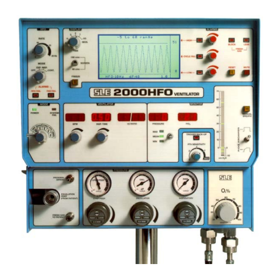
2.1 Front Panel 2.1.1 Front panel controls Power on and mode switch. HFO mode switch. HFO rate switch. Screen switch Time control switch. Display Freeze button. Display screen. Low alarm adjustment control. High alarm adjustment control. Cycle fail alarm adjustment control. Alarm Reset button. - Page 14 Manual breath button. Pressure wave selector switch. Airway pressure monitoring selection switch. PTV sensitivity control. blender control. inlet. Medical air inlet. Inspiratory pressure regulator. Oscillator pressure regulator. CPAP/PEEP pressure regulator. Fresh gas to patient port. Exhalation block. Pressure monitoring port. Inspiration time control.
-
Page 15: Back Panel
2.2 Back Panel 1) Auxiliary Output 2) FIO Calibration adjustment. 3) Running time meter - pneumatic module 4) Fuse holders 5) Product information plate 6) FIO Adjustment Tool 7) Fan and Filter. 8) Filter only. Issue 10 (01/10/2004) Page 15 of 258... -
Page 16: Electronic Module
2.3 Electronic Module Board positions within the electronic unit The Electronic module is shielded against EM interference, these shields must be removed taking care not to damage the contact fingers at the connecting edges. Position of the boards within the electronic module. HFO Main Board Assembly (A0736/03) Ventilator CPU Board Assembly (A0702/04) Motor Drive Board Assembly (A0739/02) - Page 17 Issue 10 (01/10/2004) Page 17 of 258...
-
Page 18: Access To The Sle2000 Hfo
3. Access to the SLE2000 HFO Caution: All electrical and pneumatic connections must be disconnected before attempting to gain access to either the Electronic or Pneumatic modules. The SLE 2000 HFO consists of two linked modules, Electronic and Pneumatic Electronic Module... -
Page 19: Pneumatic Module
3.2 Pneumatic Module 1. Open side flap. 2. Remove 2 screws at rear and 2 screws at base of unit. 3. Lift complete unit from base. The unit can then be placed on the work surface upside down. (See section 3.3 on page 20) Issue 10 (01/10/2004) Page 19 of 258... -
Page 20: Separating The Two Modules
3.3 Separating the two modules Invert the ventilator to gain access to the base of the pneumatic unit (see section 3.2 on page 19). 1. Remove the four screws 2. Remove proximal airway pressure tube connection 3. Remove fresh gas monitoring tube connection 4. -
Page 21: Removal Of The Oxygen Cell
3.4 Removal of the oxygen cell Trapped Screw In There are two types of oxygen cell fittings. Screw in and Trapped. 3.4.1 Screw in method 1. Gain access to the pneumatic module (see section 3.2 on page 19). 2. Release the electrical connector from the plastic clip and disconnect. 3. -
Page 22: Removal Of The Motor Assembly
Firstly gain access to the pneumatic module (see section 3.2 on page 19) 3.5.1 Motor assemblies The SLE 2000 HFO ventilator has three models of motor assembly, Part Nº N2524, N2524/01 and N2524/02. The first step is to ascertain which motor assembly is fitted to your ventilator. - Page 23 3. Remove the 2 screws (3) securing the orifice block. 4. Remove the 2 screws (4) retaining the motor assembly. 5. Remove the 2 screws (5) retaining the cover plate (6) and lift clear 6. Remove the final screw (7) retaining the motor assembly 7.
-
Page 24: Removal Of N2524/01 Or N2524/02 Motor Assembly
3.5.3 Removal of N2524/01 or N2524/02 motor assembly 1. Fully unscrew the retaining nuts on the two pneumatic connectors (1) and remove the two tubes. Note that one of the connectors is marked for identification on re-assembly. 2. Pull out the grommet retaining the loom (3) and disconnect the 8-way Molex connector (4). Page 24 of 258 Issue 10 (01/10/2004) - Page 25 3. Remove the 2 screws (5) securing the orifice block 4. Remove the 2 screws (6) retaining the motor assembly. 5. Remove the 2 screws (7) retaining the cover plate (8) and lift clear 6. Remove the final screw (9) retaining the motor assembly 7.
- Page 26 This page is intentionally blank. Page 26 of 258 Issue 10 (01/10/2004)
- Page 27 Issue 10 (01/10/2004) Page 27 of 258...
-
Page 28: Cleaning, Disinfection And Sterilization
DO NOT steam autoclave the SLE 2000 HFO or otherwise subject it to temperatures above 62°C. DO NOT immerse any part of the SLE 2000 HFO in any liquid, with the exception of the expiratory exhalation block (SLE part No N0635). -
Page 29: Cleaning, Disinfection & Sterilization Chart
• Lift up lever (A) on side of ventilator and lower side flap. • Remove the silencer (B) by pulling it through the hole at the rear. • Remove the exhalation block (C) by firstly taking hold of the block and then pulling it out towards you without the need for undue force. -
Page 30: Disinfection Method
4.5 Sterilization method The silencer SLE part Nº N2186 and exhalation block SLE part Nº N0635 must be sterilized between use on patients. The ventilator cannot be sterilized. The exhalation block must be cleaned as an essential prerequisite to sterilization. -
Page 31: Filter Systems
The filter can be autocalved a maximum of 25 times within its anticipated service life of 12 months. For other makes of bacterial filter please refer to manufacturers instructions. 5.2 Bacterial filter, SLE Part Nº:N2587 (Single use) This single use bacterial filter is fitted onto the exhalation block outlet. This filter should be disposed of in accordance with local hospital authority guidelines. -
Page 32: Maintenance
6. Maintenance 6.1 Monthly Operational Checks 6.1.1 Battery condition and LED display test. Switch unit to CPAP position. All alarms should sound for two seconds. All digital displays should show a sequence of digits from 0 to 9 and all alarm LED's (except the HFO fail and Block LED) will be on for the duration of this test. -
Page 33: Inspiratory Nozzle
6.1.4 Inspiratory Nozzle Set ventilator to CMV, 60BPM, 0.5 sec inspiration time. Set a driving gas pressure to read 40cmH O. Peak inspiration pressure should be between 37 and 43 cmH 6.1.5 CPAP pressure check Set ventilator to CPAP, HFO mode off. Check that the CPAP pressure regulator can be set up to produce a pressure of at least 35 cmH 6.1.6 HFO pressure check Check that the Oscillator pressure regulator can be set up to produce a peak to peak pressure... -
Page 34: Servicing
A sevice should be completed every 6 months. This maintenace is inteneded to be carried out in the hosptial. Service of this ventilator should only be carried out by an SLE trained hospital engineer or an SLE service engineer. The ventilator is fitted with a time elapsed meter to assist in checking operational use and service periods. - Page 35 Issue 10 (01/10/2004) Page 35 of 258...
-
Page 36: Overhaul
Overhaul should be carried out at a maximum of 10,000 hours operation or every two years of service which ever is sooner. This overhaul will be performed by an SLE trained hospital engineer or an SLE service engineer at SLE. - Page 37 Issue 10 (01/10/2004) Page 37 of 258...
-
Page 38: Exchanging A Pneumatic Unit
8. Exchanging a Pneumatic Unit The following details how to exchange the pneumatic unit of the SLE 2000 HFO. Firstly gain access to the ventilator (See section ’3. Access to the SLE2000 HFO’ on page 18) and remove the pneumatic unit (See section ’3.3 Separating the two modules’ on page 20). - Page 39 Issue 10 (01/10/2004) Page 39 of 258...
-
Page 40: Sle 2000 Hfo Set Up And Calibration
9. SLE 2000 HFO Set up and Calibration 9.1 Recommended Equipment The following equipment is recommended to perform this calibration procedure; A Standard SLE Patient Circuit (N2029) A Test Lung. A Calibrated 20MHz+ Storage Oscilloscope. A Calibrated DVM able to resolve 1mV. -
Page 41: Step 2: Electronic Module Setup
11. Step 2: Electronic Module Setup 11.1 Power Supply Unit 11.1.1 Voltage verification and setting Check the following pin voltages with mains applied to the unit. Measure between pins; Voltage 1(GND) and 3 on PSU: +5.12V ± 0.1V (see below for adjustment) 1(GND) and 9 on PSU: +12V ±... -
Page 42: Ventilator Cpu Board (A0702/04)
11.2 Ventilator CPU Board (A0702/04) To work on the A0702/04 CPU board requires removal of the A0736/03 board. Removal of the A0736/03 board cause’s the supply voltage to rise. It is necessary to insert the dummy load resistor (15 Ohms 1.5W) between PLA pin 1a/b and PLA pin 32a/b to mimic the power drain of the removed board. -
Page 43: Fresh Gas Block And Leak Alarm
Switch ventilator on to CPAP mode and confirm that fresh gas flow is :5L/min ± 0.25L/min Connect the flow regulator assembly in the following configuration: SLE 2000 HFO Ventilator To RT200 Calibration Analyser Ventilator Fresh Gas Port or equivalent. -
Page 44: Maximum Inspiration Time
11.2.6 Maximum Inspiration Time Select CPAP mode With max. insp. time control turned fully clockwise adjust RV6 to display:3.00 secs. 11.2.7 Airway Trigger Calibration Set up the ventilator electrically and pneumatically and fit a standard patient circuit with a 2ml syringe fitted to the ET manifold. -
Page 45: Motor Drive Board (A0739/02)
11.3 Motor Drive Board (A0739/02) Switch HFO mode to EXP. Turn motor speed control fully clockwise. Monitor TP1 with a calibrated oscilloscope or calibrated timer/counter. Adjust RV1 to produce a frequency of: 4KHz ±40Hz (250ms±25ms) Turn motor speed control fully anti-clockwise Verify that frequency at TP1 is: 600Hz ±60Hz(1.67ms±0.167ms)Factory set. -
Page 46: Bargraph Calibration
Adjust P11 so that displayed high alarm level: 62 cmH Adjust P13 so that displayed cycle fail level: 50 cmH Adjust P12 so that displayed low alarm level: 40 cmH Confirm that the fresh gas dump solenoid is de-activated at a position above the high alarm setting of between: 0cm and 2cm 11.4.2 Bargraph Calibration... -
Page 47: Hfo Rate Display
11.4.6 HFO Rate Display Ensure that the motor speeds have been calibrated before performing this adjustment. Switch the HFO mode to continuous and ventilator mode to CPAP a) Turn motor speed control fully anti-clockwise. Adjust P3 to produce a displayed rate of: b) Turn motor speed control fully clockwise. -
Page 48: Pressure Drift Monitor Board (A0745)
11.6 Pressure Drift Monitor Board (A0745) Procedure depends on which issue of board is fitted. Issue 1 (recognisable as only having two potentiometers) Pay special attention to the indicated polarities when measuring voltages. a) Set the DC voltage between (High) (+) and (Low)(-) to +180mV ±5mV using RV1. b) Set the DC voltage between (High) (+) and (Diff)(-) to +90mV ±5mV using RV2. -
Page 49: Stage 3: Pneumatic Module Final Setup
12. Stage 3: Pneumatic Module Final Setup Monitor the proximal airway pressure with a standard test manometer. With the PIP regulator turned fully anticlockwise, turn CPAP regulator fully clockwise and ensure that the CPAP pressure exceeds 35cmH O. Turn CPAP regulator fully anticlockwise and check that the airway pressure is now less than 1cmH Set high pressure alarm fully clockwise. -
Page 50: Operational Verification
All 7 Segment displays increment from 0 to 9 (Check all segments are operative) LCD firmware initialises & displays SLE logo. With mode switch set successively in CPAP, CMV, PTV, and SIMV, disconnect the mains supply & confirm that the Mains Failure audible alarm is activated in each posi- tion. -
Page 51: Hfo Modulation
By selecting a range of CPAP pressures from O cmH O to 30 cmH O in 10 cmH steps, and adjusting the CPAP alarm setting to the CPAP pressure, observe that the displayed CPAP pressure plateau and bargraph display correspond with alarm line and LED Segment, respectively. -
Page 52: Display Timebase
Switch to CMV mode. Select 30 BPM with 1 second INSP time. Set an inspiratory pres- sure of 30 cmH O and a CPAP pressure of 0 cmH O. Set HIGH alarm to 60 cmH CYCLE FAIL alarm to 20 cmH O, and LOW alarm to -20 cmH O. -
Page 53: Freeze Push-Button
13.5 Freeze Push-Button Press FREEZE push-button and confirm that ‘FREEZE’ message is displayed for 1 minute ± 3 seconds. Displayed waveform should not update during this period. After 1 minute the display should revert to updating mode. By pressing FREEZE push-button repeatedly check that the FREEZE function can be toggled on and off. -
Page 54: Simv Mode
13.10 SIMV Mode Check operation of the SIMV trigger system, ensuring that the back-up audible beep is activated during machine initialised breaths. Check that the SIMV BPM rate may be controlled by adjustment of the BPM control and display. 13.11 Block and Leak alarms Under simulated temperature conditions for normal operation (28°C-32°C). -
Page 55: Verification Of Hfo Safety Solenoid Sv5
Check that CPAP pressures are in accord with decal markings for 10, 20, 30 and 30 and 40 cmH Check that INSPIRATORY pressures are in accord with decal markings for 10, 20, 30, 40, 50 and 60 cmH Check that OSCILLATOR pressures are in accord with decal markings for 10, 20, 30, 40 and 50 cmH O, with the ET Tube occluded. -
Page 56: Hfo Neep Verification
13.15 HFO NEEP Verification This verification is only for ventilators fitted with HFO NEEP. Set vent to HFO Cont. and set the frequency to 10Hz. Set the CPAP regulator fully anti- clockwise. Set the OSCILLATOR pressure regulator to 100cmH Occlude the ET patient connector Verify that the mean pressure level is not greater than +6 cmH Note: If the reading is outside the stated limits check the seating of the exhalation block and that the rotating jet assembly jets are not blocked. - Page 57 Issue 10 (01/10/2004) Page 57 of 258...
-
Page 58: Technical Specification
14. Technical Specification 14.1 Operating Modes 14.1.1 Conventional Ventilation Modes: OFF,CPAP,CMV,PTV,SIMV BPM Range: 1-150 breaths per minute Inspiratory Time: 0.1-3.0 seconds I:E Range: 9.9:1 - 1:9.9 calculated from BPM and Inspiratory time settings. CPAP Pressure: 0cmH O to 35cmH O minimum. Inspiratory Pressure: 0cmH O to 60cmH... -
Page 59: Controls
Mute active for 60 seconds (approx.) Display Freeze push button: Active for 60 seconds (approx.) Trigger Sensitivity Control: Range: 2ml/0.5 sec max. To 10ml/0.5sec min. when using SLE N2188 patient circuit. HIGH, CYCLE FAIL, LOW pressure Resolution: 1cmH O on LCD, 2cmH O on bar- alarm setting controls: graph. -
Page 60: Alarms
14.4 Alarms Audible only: Loss of mains supply: Battery powered alarm Loss of Air or O supply: Blender alarm. Audible and Visual: HIGH CIRCUIT PRESSURE CYCLE FAIL LOW CIRCUIT PRESSURE FRESH GAS BLOCK FRESH GAS LEAK or TOTAL GAS SUPPLY FAIL (loss of air and O SYSTEM FAIL: HFO FAIL, FAN FAIL. -
Page 61: Circuit Descriptions
15. Circuit Descriptions 15.0.1 Front Panel Board Assembly (A0700/02) This board is mounted behind the front panel of the SLE2000 HFO Electronic unit and is above the A0701/02 board. On this board are the seven segment LED displays for; BPM, INSP, I:E, PRESSURE and FIO . -
Page 62: Hfo Main Board Assembly (A0736/03)
The Mains Failure Alarm relay-RLl is energised from the 5.12 volt logic supply and holds pins 1 and 14 open. Should the relay de-energise contacts 1 and 14 will close, and a battery powered alarm will be activated via connections PLB 18a and PLB 20a. PTR1 monitors proximal airway pressure in the range -60 to +60 cmH O. -
Page 63: Bargraph Display Board Assembly (A0737)
15.0.4.4 Dual Fan Fail Alarm This circuit operates audible and visual alarms if the speed of either fan motor falls below approx. 75% of normal rate. Current pulses from the motor commutation develop pulses which are compared with a reference voltage in U23A and B. This results in output pulses from U23/ 1 and U23/7 for each fan. -
Page 64: Alarm Board Assembly (A0738/02)
proximal airway pressure signal. This multiplexed signal is fed into four bargraph drivers (LM3914's) which in turn drive four 10*LED arrays. For each level of the signal only one of the 40 LED's is illuminated. 15.0.6 Alarm Board Assembly (A0738/02) 15.0.6.1 Alarm Conditioning Circuit The Alarm circuit comprises U1, U2 and U3. -
Page 65: Motor Drive Board Assembly (A0739/02)
2 at revision C. See drawing “AS/A0756 HFO Motor Start Up PCB Issue 2” on page 143. See “SI 000101 Modification of SLE 2000 HFO motor drive circuit board.” on page 233 for further details on how to modify the board. -
Page 66: Pressure Drift Monitor Board Assembly (A0745)
15.0.8 Pressure Drift Monitor Board Assembly (A0745) The Purpose of this board is to provide an output signal if the difference between the pressure transducer signal on the A0702 board and the pressure transducer signal on this board differ by more than a set voltage (determined by RV1) Op amp U1B is used to generate an 8VDC supply from the 12VDC. -
Page 67: Graphic Lcd Module
15.0.10 Graphic LCD Module The Graphic LCD module is a 240 × 128 pixel display. It incorporates a built-in LCD controller with an on-board character generator, ROM and RAM. The LCD is a transmissive type with CCFL (Cold Cathode Fluorescent) backlighting provided by a tube mounted on the lower edge of the module. -
Page 68: Pneumatic Circuit
15.1 Pneumatic Circuit For access to the pneumatic unit section 3.2 on page 19 Schematic representation of the SLE 2000 HFO pneumatics; Image:sm0006_001 Page 68 of 258 Issue 10 (01/10/2004) -
Page 69: Pneumatic Layout
15.1.1 Pneumatic Layout There are three possible pneumatic layouts within the pneumatic unit. Schematic 1. For HFO ventilators with no proximal airway purge. Schematic 2. For HFO ventilators with Version 1 proximal airway purge. Issue 10 (01/10/2004) Page 69 of 258... -
Page 70: How To Identify Proximal Airway Purge Type
Schematic 3. For HFO ventilators with Version 2 proximal airway purge. 15.1.2 How to Identify Proximal Airway Purge Type To identify the type of purge fitted to the ventilator, locate the proximal airway tube where it exits the electronic unit. This will be the starting point for identification. -
Page 71: Conventional Ventilation
page 164). 15.1.2.3 Ventilator with Version 2 Proximal Airway Purge The regulator REG 3 should have all four outlet ports used.The proximal airway tube should be split by a "Y" connector. One limb should run to the proximal airway outlet port, the other limb should contain another "Y"... -
Page 72: Hfo Operation
When the fresh gas is dumped a residual flow of 1 LPM0.8 to 1.5LPM is maintained by REG3 in order to prevent excessive temperatures in the humidification chamber. Both the SLE2000 single use patient circuit (N2188) and the reusable patient circuit (N2220) incorporate a restrictor close to the inspiratory port of the ET connector. - Page 73 Issue 10 (01/10/2004) Page 73 of 258...
-
Page 74: Sle2000 Hfo Troubleshooting Chart
16. SLE2000 HFO Troubleshooting Chart Symptom Possible Cause Remedy Leak Alarm - audible & visual Incorrect circuit fitted. Replace with correct circuit -P/No. N2188 or variant. Damaged circuit fitted. Replace with new circuit. Humidifier chamber. Replace chamber. High alarm condition. High alarm LED illuminated - reset Insp. - Page 75 Intermittent alarm on start up Only in oscillation while CR circuit is of Oscillation. charging, if persistent check soft- ware version with SLE Life Support Service Dept. Proximal Airway line discon- Reconnect tubing. nected. Replace solenoid and soak test ven- SV1 - Solenoid failure.
- Page 76 PEAK INSP. PRESSURE Faulty patient circuit. Replace circuit. Unable to set desired pres- sure. Incorrectly assembled patient Reassemble as per drawing sup- circuit. plied with circuit. Exhalation block - located Relocate the block assembly. incorrectly. Regulator cap is in LOCKED Pull regulator cap out to release position.
- Page 77 Displayed Faults Displayed in I:E window Replace pot assembly. HELP message. -O/S of BPM or INSP pot. SOL message. Displayed in BPM window Check wiring and solenoids. O/S of solenoid circuitry. Use dummy load. LCD measurements vary from that displayed by pressure display.
- Page 78 This page is intentionally blank. Page 78 of 258 Issue 10 (01/10/2004)
- Page 79 Issue 10 (01/10/2004) Page 79 of 258...
-
Page 80: Circuit Details
17. Circuit Details 17.1 AS/A0700/02 Display Board Assembly Page 80 of 258 Issue 10 (01/10/2004) -
Page 81: Cd/A0700/02 Display Board Circuit Diagram
17.1.1 CD/A0700/02 Display Board Circuit Diagram Issue 10 (01/10/2004) Page 81 of 258... - Page 82 PARTS LIST Finished Item Stock Number A0700/02 Finished Item Description Display Pcb Assy (HFO) Bill of materials AS/A0700/02 Issue 4 Part Number Component Description Used Component Reference(s) J0700 Display Board blank 1.00 ITEM 1 (PCB) D0308 LED Green Rectangular LGB480EH 1.00 LED 6 L0008 Display extender board...
-
Page 83: As/A0701/02 Led Pcb Assembly
17.2 AS/A0701/02 LED PCB Assembly Issue 10 (01/10/2004) Page 83 of 258... -
Page 84: Cd/A0701/02 Led Board Circuit Diagram
17.2.1 CD/A0701/02 LED Board Circuit Diagram Page 84 of 258 Issue 10 (01/10/2004) - Page 85 PARTS LIST Finished Item Stock Number A0701/02 Finished Item Description LED Pcb Assy (HFO) Bill of materials AS/A0701/02 Issue 2 Part Number Component Description Used Component Reference(s) J0701 LED pcb blank 1.00 ITEM 1 (PCB) D0308 LED Green Rectangular LGB480EH 3.00 LED2,3,4 D0508 74HC00...
- Page 86 CPU Board AS/A0702/04 AS/A0702/04 Issue 2: Standard board (See board drawing AS/A0702/04 issue 2 on page 87 and circuit diagram CD/A0702/04 issue 2 on page 89). Stabilization of leak alarm trigger threshold AS/A0702/04 Issue 3: Addition of capacitor C0481 to stabilise leak alarm trigger threshold (See board drawing AS/A0702/04 issue 3 on page 93 and circuit diagram CD/A0702/04 issue 3 on page 95).
-
Page 87: As/A0702/04 Cpu Pcb Issue 2 Sheet 1 Of 2
17.3 AS/A0702/04 CPU PCB Issue 2 Sheet 1 of 2 Issue 10 (01/10/2004) Page 87 of 258... -
Page 88: As/A0702/04 Cpu Pcb Issue 1 Sheet 2 Of 2
17.3.1 AS/A0702/04 CPU PCB Issue 1 Sheet 2 of 2 Page 88 of 258 Issue 10 (01/10/2004) -
Page 89: Cd/A0702/04 Cpu Board Circuit Diagram Issue 2
17.3.2 CD/A0702/04 CPU Board Circuit Diagram Issue 2 A3 version on page 189 of circuit diagram appendix. Issue 10 (01/10/2004) Page 89 of 258... - Page 90 PARTS LIST Finished Item Stock Number A0702/04 Finished Item Description Ventilator CPU PCB Assy' CE MK Bill of materials AS/A0702/04 Issue 2 Part Number Component Description Used Component Reference(s) J0702 Ventilator CPU pcb blank 1 00 Each ITEM 1 (PCB Rev D) Check pressure transducer type (ITEM PTR2)and read note for component pre-fix C0256...
- Page 91 Part Number Component Description Used Component Reference(s) D0581 LMC660AIN 2 00 Each U13,U202 D0584 CD40106BE 1 00 Each U200 D0636 IRLU110 power MOSFET,TO-251 1 00 Each D0638 ZTX450Each 1 00 Each D0644/01 P80C32EBPN 8-bit CMOS CPU 1 00 Each M0626 Jumper Link 1 00 Each ITEM 5...
- Page 92 Part Number Component Description Used Component Reference(s) R0504 2.2M Resistor 1% 0.25W 1.00 Each R0506 3.3M Resistor 1% 0.25W SMA0207 3.00 Each Rll,R505,R506 R0555 470K x 8 Resistor Network 1.00 Each R0556 10K x 8 Resistor Network 1.00 Each R0571 10k Resistor 1% 0.125W M/Film 2.00 Each R213 &...
-
Page 93: As/A0702/04 Cpu Pcb Issue 3 Sheet 1 Of 2
17.4 AS/A0702/04 CPU PCB Issue 3 Sheet 1 of 2 Issue 10 (01/10/2004) Page 93 of 258... -
Page 94: As/A0702/04 Cpu Pcb Issue 3 Sheet 2 Of 2
17.4.1 AS/A0702/04 CPU PCB Issue 3 Sheet 2 of 2 Page 94 of 258 Issue 10 (01/10/2004) -
Page 95: Cd/A0702/04 Cpu Pcb Circuit Diagram Issue 3
17.4.2 CD/A0702/04 CPU PCB Circuit Diagram Issue 3 A3 version on page 191 of circuit diagram appendix. Issue 10 (01/10/2004) Page 95 of 258... - Page 96 PARTS LIST Finished Item Stock Number A0702/04 Finished Item Description Ventilator CPU PCB Assy' CE MK Bill of materials AS/A0702/04 Issue 3 Part Number Component Description Used Component Reference(s) J0702 Ventilator CPU pcb blank 1 00 Each ITEM 1 (PCB Rev D) Check pressure transducer type (ITEM PTR2)and read note for component pre-fix C0256...
- Page 97 Part Number Component Description Used Component Reference(s) D0580 TLC555CP 1 00 Each D0581 LMC660AIN 2 00 Each U13,U202 D0584 CD40106BE 1 00 Each U200 D0636 IRLU110 power MOSFET,TO-251 1 00 Each D0638 ZTX450Each 1 00 Each D0644/01 P80C32EBPN 8-bit CMOS CPU 1 00 Each M0626 Jumper Link...
- Page 98 Part Number Component Description Used Component Reference(s) R0501 1.0M Resistor 1% 0.25W SMA0207 2.00 Each R211,R212 R0504 2.2M Resistor 1% 0.25W 1.00 Each R0506 3.3M Resistor 1% 0.25W SMA0207 3.00 Each Rll,R505,R506 R0555 470K x 8 Resistor Network 1.00 Each R0556 10K x 8 Resistor Network 1.00 Each...
-
Page 99: As/A0702/04 Cpu Pcb Issue 5 Sheet 1 Of 2
17.5 AS/A0702/04 CPU PCB Issue 5 Sheet 1 of 2 Issue 10 (01/10/2004) Page 99 of 258... -
Page 100: As/A0702/04 Cpu Pcb Issue 5 Sheet 2 Of 2
17.5.1 AS/A0702/04 CPU PCB Issue 5 Sheet 2 of 2 Page 100 of 258 Issue 10 (01/10/2004) -
Page 101: Cd/A0702/04 Cpu Pcb Circuit Diagram Issue 4
17.5.2 CD/A0702/04 CPU PCB Circuit Diagram Issue 4 A3 version on page 193 of circuit diagram appendix. Issue 10 (01/10/2004) Page 101 of 258... - Page 102 PARTS LIST Finished Item Stock Number A0702/04 Finished Item Description Ventilator CPU PCB Assy' CE MK Bill of materials AS/A0702/04 Issue 5 Part Number Component Description Used Component Reference(s) J0702 Ventilator CPU pcb blank 1 00 Each ITEM 1 (PCB Rev D) Check pressure transducer type (ITEM PTR2)and read note for component pre-fix C0256...
- Page 103 Part Number Component Description Used Component Reference(s) D0580 TLC555CP 1 00 Each D0581 LMC660AIN 2 00 Each U13,U202 D0584 CD40106BE 1 00 Each U200 D0636 IRLU110 power MOSFET,TO-251 1 00 Each D0638 ZTX450Each 1 00 Each D0644/01 P80C32EBPN 8-bit CMOS CPU 1 00 Each M0626 Jumper Link...
- Page 104 Part Number Component Description Used Component Reference(s) R0501 1.0M Resistor 1% 0.25W SMA0207 2.00 Each R211,R212 R0504 2.2M Resistor 1% 0.25W 1.00 Each R0506 3.3M Resistor 1% 0.25W SMA0207 3.00 Each Rll,R505,R506 R0555 470K x 8 Resistor Network 1.00 Each R0556 10K x 8 Resistor Network 1.00 Each...
- Page 105 Main Board AS/A0736/03 Revision E: Standard board (See board drawing AS/A0736/03 issue 3 on page 106 and circuit diagram CD/ A0736/03 issue 2 on page 107). Revision F: U7 timer (ZN1034E) no longer manufactured and replaced by timer (NE555N) which required additional components. (See board drawing AS/A0736/03 issue 4 on page 111 and circuit diagram CD/ A0736/03 issue 3 on page 112).
-
Page 106: As/A0736/03 Main Pcb Revision E Issue 3
17.6 AS/A0736/03 Main PCB Revision E Issue 3 Note: Check the revision status of the main board Page 106 of 258 Issue 10 (01/10/2004) -
Page 107: Cd/A0736/03 Main Pcb Circuit Diagram Issue 2
17.6.1 CD/A0736/03 Main PCB Circuit Diagram Issue 2 (For Revision E Main Board ) Note: Check the revision status of the main board A3 version on page 195 of circuit diagram appendix. Issue 10 (01/10/2004) Page 107 of 258... - Page 108 Note: Check the revision status of the main board PARTS LIST Finished Item Stock Number A0736/03 Finished Item Description HFO Main PCB Assy'CE Papst Fan Bill of materials AS/A0736/03 Issue 3 Part Number Component Description Used Component Reference(s) J0736 HFO Main Board blank 1.00 Each ITEM 1 (PCB Rev E) C0224...
- Page 109 Part Number Component Description Used Component Reference(s) D0576 27C128A-20 1.00 Each D0578 74AC540 2.00 Each U4 & U21 D0580 TLC555CP 1.00 Each D0581 LMC660AIN 3.00 Each U28-U30 D0585 BC327 1.00 Each D0594 ZN1034 1.00 Each D0595 74LS148N 1.00 Each D0596 Crystal 8.OMhz 1.00 Each XTL1...
- Page 110 Part Number Component Description Used Component Reference(s) R0463 10K Resistor 1% 0.25W SMA0207 30.00 Each R5,13,29,35,41,42,52,53,5 7, 58,61 ,62,64,67,68,70, 72,73,75,76,81,86,88,89,9 1,92, 99, 100 ,102,R114 R0464 12.1K Resistor 1% 0.25W SMA020 4.00 Each R69,71,74,R101 R0467 15K Resistor 1% 0.25W SMA0207 3.00 Each R56,R116 &...
-
Page 111: As/A0736/03 Main Pcb Revision F Issue 4
17.7 AS/A0736/03 Main PCB Revision F Issue 4 Note: Check the revision status of the main board Issue 10 (01/10/2004) Page 111 of 258... -
Page 112: Cd/A0736/03 Main Pcb Circuit Diagram Issue 3
17.7.1 CD/A0736/03 Main PCB Circuit Diagram Issue 3 (For Revision F Main Board) Note: Check the revision status of the main board A3 version on page 197 of circuit diagram appendix. Page 112 of 258 Issue 10 (01/10/2004) - Page 113 Note: Check the revision status of the main board PARTS LIST Finished Item Stock Number A0736/03 Finished Item Description HFO Main PCB Assy'CE Papst Fan Bill of materials AS/A0736/03 Issue 4 Part Number Component Description Used Unit Component Reference(s) J0736 HFO Main Board blank 1.00 Each ITEM 1 (PCB Rev E)
- Page 114 Part Number Component Description Used Unit Component Reference(s) D0531 4013 1.00 Each D0544 4538 1.00 Each D0576 27C128A-20 1.00 Each D0578 74AC540 2.00 Each U4 & U21 D0580 TLC555CP 1.00 Each D0581 LMC660AIN 3.00 Each U28-U30 D0585 BC327 1.00 Each D0594 ZN1034E Precision Timer IC 0.00 Each...
- Page 115 Part Number Component Description Used Unit Component Reference(s) R0456 5.6K Resistor 1% 0.25W SMA0207 1.00 Each R0463 10K Resistor 1% 0.25W SMA0207 30.00 Each R5,13,29,35,41,42,52,53,5 7, 58,61 ,62 ,64,67,68,70, 72,73,75, 76,81,86,88, 89,91,92,99, 100 ,102,R114 R0464 12.1K Resistor 1% 0.25W SMA020 4.00 Each R69,71,74,R101 R0467...
-
Page 116: As/A0736/03 Main Pcb Revision G Issue 5
17.8 AS/A0736/03 Main PCB Revision G Issue 5 Note: Check the revision status of the main board Page 116 of 258 Issue 10 (01/10/2004) -
Page 117: Cd/A0736/03 Main Pcb Circuit Diagram Issue 4
17.8.1 CD/A0736/03 Main PCB Circuit Diagram Issue 4 (For Revision G Main Board) Note: Check the revision status of the main board A3 version on page 199 of circuit diagram appendix. Issue 10 (01/10/2004) Page 117 of 258... - Page 118 Note: Check the revision status of the main board PARTS LIST Finished Item Stock Number A0736/03 Finished Item Description HFO Main PCB Assy'CE Papst Fan Bill of materials AS/A0736/03 Issue 5 Part Number Component Description Used Unit Component Reference(s) J0736 HFO Main Board blank 1.00 Each ITEM 1 (PCB Rev E)
- Page 119 Part Number Component Description Used Unit Component Reference(s) D0544 4538 1.00 Each D0576 27C128A-20 1.00 Each D0578 74AC540 2.00 Each U4 & U21 D0580 TLC555CP 1.00 Each D0581 LMC660AIN 3.00 Each U28-U30 D0585 BC327 1.00 Each D0594 ZN1034E Precision Timer IC 0.00 Each Replaced by DO457 CN0619 for REV-F ofPCB Blank...
- Page 120 Part Number Component Description Used Unit Component Reference(s) R0463 10K Resistor 1% 0.25W SMA0207 32.00 Each R5,13,29,35,41,42, 48, 52, 53, 57, 58,61,62 ,64, 67, 68, 70, 72 ,73 ,75 , 76, 81,86,88, 89,91,92,99, 100 ,102,114 R122 R0464 12.1K Resistor 1% 0.25W SMA020 4.00 Each R69,71,74,R101 R0467...
-
Page 121: As/A0736/03 Main Pcb Revision G Issue 5
17.9 AS/A0736/03 Main PCB Revision G Issue 5 Note: Check the revision status of the main board Issue 10 (01/10/2004) Page 121 of 258... -
Page 122: Cd/A0736/03 Main Pcb Circuit Diagram Issue 5
17.9.1 CD/A0736/03 Main PCB Circuit Diagram Issue 5 (For Revision G Main Board) Note: Check the revision status of the main board A3 version on page 201 of circuit diagram appendix. Page 122 of 258 Issue 10 (01/10/2004) - Page 123 Note: Check the revision status of the main board PARTS LIST Finished Item Stock Number A0736/03 Finished Item Description HFO Main PCB Assy'CE Papst Fan Bill of materials AS/A0736/03 Issue 6 Part Number Component Description Used Unit Component Reference(s) J0736 HFO Main Board blank 1.00 Each ITEM 1 (PCB Rev E)
- Page 124 Part Number Component Description Used Unit Component Reference(s) D0531 4013 1.00 Each D0544 4538 1.00 Each D0576 27C128A-20 1.00 Each D0578 74AC540 2.00 Each U4 & U21 D0580 TLC555CP 1.00 Each D0581 LMC660AIN 3.00 Each U28-U30 D0585 BC327 1.00 Each D0594 ZN1034E Precision Timer IC 0.00 Each...
- Page 125 Part Number Component Description Used Unit Component Reference(s) R0463 10K Resistor 1% 0.25W SMA0207 32.00 Each R5,13,29,35,41,42, 48, 52, 53, 57, 58,61,62 ,64, 67, 68, 70, 72 ,73 ,75 , 76, 81,86,88, 89,91,92,99, 100 ,102,114 R122 R0464 12.1K Resistor 1% 0.25W SMA020 4.00 Each R69,71,74,R101 R0467...
-
Page 126: As/A0737/01 Bargraph Display Pcb Assembly
17.10 AS/A0737/01 Bargraph Display PCB Assembly Page 126 of 258 Issue 10 (01/10/2004) -
Page 127: Cd/A0737/01 Bargraph Display Pcb Circuit Diagram
17.10.1 CD/A0737/01 Bargraph Display PCB Circuit Diagram Issue 10 (01/10/2004) Page 127 of 258... - Page 128 PARTS LIST Finished Item Stock Number A0737/01 Finished Item Description Bargraph Display Pcb Assembly Bill of materials AS/A0737/01 Issue 2 Part Number Component Description Used Unit Component Reference(s) J0737 Bargraph Board blank 1.00 ITEM 1 (PCB) C0450 0.1uF Capacitor 63V 10% MKS2 3.00 C1,C2,C4 R0429...
-
Page 129: As/A0738/02 Alarm Pcb Assembly
17.11 AS/A0738/02 Alarm PCB Assembly Issue 10 (01/10/2004) Page 129 of 258... -
Page 130: Cd/A0738/02 Alarm Pcb Circuit Diagram
17.11.1 CD/A0738/02 Alarm PCB Circuit Diagram Page 130 of 258 Issue 10 (01/10/2004) - Page 131 PARTS LIST Finished Item Stock Number A0738/02 Finished Item Description ALARM PCB ASSEMBLY Bill of materials AS/A0738/02 Issue 3 Part Number Component Description Used Unit Component Reference(s) J0738/01 Alarm board pcb Rev.D 1.00 ITEM 1 N2179 Battery Holder (AA size) 1.00 N2096 SMA-24L Audible Alarm 98dB...
- Page 132 Part Number Component Description Used Unit Component Reference(s) D0634 ZN458A 1.00 S0242 IC Socket 14 way DIL 2.00 ITEM 5 (U1,U5) S0237 IC Socket 20 way DIL 1.00 ITEM 6 (U2) S0241 IC Socket 8 way DIL 2.00 ITEM 7 (U3 & U4) H3210 M3 x 10 Csk Hd Pozi s.st 2.00...
- Page 133 (See board drawing AS/A0739/02 issue 3 on page 139 and circuit diagram CD/ A0739/02 issue 3 on page 140). Also see service information “SI 000101 Modification of SLE 2000 HFO motor drive circuit board.” on page 233. Issue 10 (01/10/2004)
-
Page 134: As/A0739/02 Motor Drive Pcb Issue 1 Sheet 1 (Revision B)
17.12 AS/A0739/02 Motor drive PCB Issue 1 Sheet 1 (Revision B) Page 134 of 258 Issue 10 (01/10/2004) -
Page 135: As/A0739/02 Motor Drive Pcb Issue 1 Sheet 2 (Revision B)
17.12.1 AS/A0739/02 Motor drive PCB Issue 1 Sheet 2 (Revision B) Issue 10 (01/10/2004) Page 135 of 258... -
Page 136: Cd/A0739/02 Motor Drive Pcb Circuit Diagram Issue 1(Revision B)
17.12.2 CD/A0739/02 Motor drive PCB Circuit Diagram Issue 1(Revision B) Page 136 of 258 Issue 10 (01/10/2004) - Page 137 PARTS LIST Finished Item Stock Number A0739/02 Finished Item Description Motor Drive PCB Assy' CE Mk Bill of materials AS/A0739/02 Issue 1 Part Number Component Description Used Unit Component Reference(s) J0739 Motor Drive Board blank 1.00 Each ITEM 1 (PCB) C0410 3.3nF Capacitor 50V 10% Ceramc 1.00 Each...
- Page 138 Part Number Component Description Used Unit Component Reference(s) M0706/03 Label,Hazard Flash (25sq.) 1.00 Each ITEM 15 M0716 Spacer hex.6.35-ID3.5 x 6.35lg 4.00 Each ITEM 13 M0718 Label, PCB Identification 1.00 Each ITEM 17 M0720 T0-3P IC Mounting Kit Silicone 1.00 Each ITEM 12 S0237 IC Socket 20 way DIL...
-
Page 139: As/A0739/02 Motor Drive Pcb Issue 3 (Revision C)
17.13 AS/A0739/02 Motor Drive PCB Issue 3 (Revision C) Issue 10 (01/10/2004) Page 139 of 258... -
Page 140: Cd/A0739/02 Motor Drive Pcb Circuit Diagram Issue 3 (Revision C)
17.13.1 CD/A0739/02 Motor drive PCB Circuit Diagram Issue 3 (Revision C) Page 140 of 258 Issue 10 (01/10/2004) - Page 141 PARTS LIST Finished Item Stock Number A0739/02 Finished Item Description Motor Drive PCB Assy' CE Mk Bill of materials AS/A0739/02 Issue 2 Part Number Component Description Used Unit Component Reference(s) J0739 Motor Drive Board blank 1.00 Each ITEM 1 (PCB) C0260 10nF Capacitor 63V 20% MKS2 1.00 Each...
- Page 142 Part Number Component Description Used Unit Component Reference(s) M0309/01 H12 x 20mm Sleeve (1.2mm I/D) 16.00 Each ITEM 90 M0463 T0220 Transistor Heatsink 2.00 Each ITEM 14 M0680/01 Heatsink (modified) 1.00 Each ITEM 2 M0706/03 Label,Hazard Flash (25sq.) 1.00 Each ITEM 15 M0716 Spacer hex.6.35-ID3.5 x 6.35lg...
-
Page 143: As/A0756 Hfo Motor Start Up Pcb Issue 2
17.14 AS/A0756 HFO Motor Start Up PCB Issue 2 Issue 10 (01/10/2004) Page 143 of 258... - Page 144 PARTS LIST Finished Item Stock Number AS/A0756 Finished Item Description HFO Start-up Motor PCB Assembly Bill of materials AS/A0756 Issue 2 Part Number Component Description Used Component Reference(s) J0756 HFO Start-up Motor Mod PCB 1.00 Each Rev A C0485 2.2uf Cap 63/50v 20% 2F4 1.00 Each D0406 1N4148...
-
Page 145: As/A0745 Pressure Drift Monitor Board Issue 1
17.15 AS/A0745 Pressure Drift Monitor Board Issue 1 Issue 10 (01/10/2004) Page 145 of 258... -
Page 146: Cd/A0745 Pressure Drift Monitor Board Circuit Diagram Issue 1
17.15.1 CD/A0745 Pressure Drift Monitor Board Circuit Diagram Issue 1 Page 146 of 258 Issue 10 (01/10/2004) -
Page 147: As/A0745 Pressure Drift Monitor Board Issue 2
17.16 AS/A0745 Pressure Drift Monitor Board Issue 2 Issue 10 (01/10/2004) Page 147 of 258... -
Page 148: Cd/A0745 Pressure Drift Monitor Board Circuit Diagram Issue 5
17.16.1 CD/A0745 Pressure Drift Monitor Board Circuit Diagram Issue 5 Page 148 of 258 Issue 10 (01/10/2004) - Page 149 PARTS LIST Finished Item Stock Number A0745 Finished Item Description HFO Pressure Drift Monitor PCB Bill of materials AS/A0745 Issue 2 Part Number Component Description Used Unit Component Reference(s) C0450 O.luF Capacitor 63V 10W MKS2 1.00 Each D0406 lN4148 2.00 Each D1,D2 D0581 LMC660AIN...
-
Page 150: Serial Interface Option Cd/A0702/03
17.17 Serial Interface Option CD/A0702/03 Page 150 of 258 Issue 10 (01/10/2004) - Page 151 PARTS LIST Finished Item Stock Number A0702/03 Finished Item Description RS423 option for A0702 pcb Part Number Component Description Used Unit Component Reference(s) D0643 HPCL 2730 2.00 U20,21 D0640 UA9636ACP 1.00 D0593 NMA0512D 1.00 D0432 7805 Regulator 1.00 D0250 BZX79C6V8 2.00 D300,301 R0443...
-
Page 152: Cd/W0308 Wireloom Issue 6
17.18 CD/W0308 Wireloom Issue 6 A3 version on page 203 of circuit diagram appendix. Page 152 of 258 Issue 10 (01/10/2004) -
Page 153: Front Panel
17.19 Front Panel Issue 10 (01/10/2004) Page 153 of 258... -
Page 154: Sk0057 Power Supply Wiring Diagram
17.20 SK0057 Power Supply Wiring Diagram Page 154 of 258 Issue 10 (01/10/2004) -
Page 155: Cd/W0307 Electronic/Pneumatic Module Interconnection
17.21 CD/W0307 Electronic/Pneumatic Module interconnection Issue 10 (01/10/2004) Page 155 of 258... -
Page 156: Electronic Chassis Sheet 1 Of 2
17.22 Electronic Chassis Sheet 1 of 2 Page 156 of 258 Issue 10 (01/10/2004) -
Page 157: Electronic Chassis Sheet 2 Of 2
17.22.1 Electronic Chassis Sheet 2 of 2 Issue 10 (01/10/2004) Page 157 of 258... - Page 158 PARTS LIST Finished Item Stock Number L0200 Finished Item Description HFO Electronic Chassis Assy CE Mark’ Bill of materials SM/L0200 Part Number Component Description Used Unit Component Reference(s) T0939 Chassis for HFO (Electronic Assy’) 1.00 ITEM 1 A0702/04 Ventilator CPU PCB Assy.(HFO) 1.00 ITEM 2 A0736/03...
- Page 159 Part Number Component Description Used Unit Component Reference(s) A0737/01 Bargraph Display Pcb Assembly 1.00 ITEM 17 A0738/02 ALARM PCB ASSEMBLY 1.00 ITEM 18 L0015 Graphic LCD Module Assy' 1.00 ITEM 19 V0226 10K Pot. Panel mt, Single turn 4.00 VR1,VR2,VR3 & VR4 V0416 10K Pot.
- Page 160 Pneumatic Chassis AS/L0203 Issue 3: For ventilator with SLE Part Nº N2524 motor assembly with Version 1 proximal airway purge. (See drawings AS/A0L0203 issue 3 on page 161). Issue 4: For ventilator with SLE Part Nº N2524/01 motor assembly with Version 2 proximal airway purge.
-
Page 161: Pneumatic Unit Assy. As/L0203 Issue 3
17.23 Pneumatic Unit Assy. AS/L0203 Issue 3 17.23.1 AS/L0203 Sheet 1 of 4 (For ventilator with SLE Part Nº N2524 motor assembly.) See “Motor assemblies” on page 22. Issue 10 (01/10/2004) Page 161 of 258... -
Page 162: As/L0203 Sheet 2 Of 4
17.23.2 AS/L0203 Sheet 2 of 4 (For ventilator with SLE Part Nº N2524 motor assembly) See “Motor assemblies” on page 22. Page 162 of 258 Issue 10 (01/10/2004) - Page 163 17.23.3 AS/L0203 Sheet 3 of 4 (For ventilator with SLE Part Nº N2524 motor assembly) See “Motor assemblies” on page 22. Issue 10 (01/10/2004) Page 163 of 258...
-
Page 164: As/L0203 Sheet 4 Of 4
17.23.4 AS/L0203 Sheet 4 of 4 (For ventilator with SLE Part Nº N2524 motor assembly) See “Motor assemblies” on page 22. Page 164 of 258 Issue 10 (01/10/2004) - Page 165 For Ventilator with SLE Part Nº N2524 motor assembly. (See “Motor assemblies” on page 22.) PARTS LIST Finished Item Stock Number L0203 Finished Item Description HFO Pneumatic Assembly CE Mk Bill of materials AS/L0203 Issue 3 Part Number Component Description...
- Page 166 Part Number Component Description Used Unit Component Reference(s) N2180 Pressure regulator 0-2 bar 1.00 Each ITEM 41 N2180/01 Blanking Plug 1/8 4.00 Each Sht 4 of drg. ITEM 25 N2181 Pressure Regulator 0-4 bar 3.00 Each ITEM 7 N2185 Microblender (UK version) 1.00 Each ITEM 6 N2185/99...
- Page 167 Part Number Component Description Used Unit Component Reference(s) T0622 Partition (Outer) 1.00 Each ITEM 71 T0624 Washer, special seal,nylon 1.00 Each Sht 4 of drg. ITEM 11 T0624/01 Washer,special seal 1/2"-20unf 1.00 Each Sht 4 of drg. ITEM 11 T0625 Spacer,M3 x 22mm lg.
- Page 168 Part Number Component Description Used Unit Component Reference(s) T0236 Fixing Block (end) 2.00 Each ITEM 3 T0237 Fixing block (small end) 1.00 Each ITEM 1 T0240 Relief Valve Cover 1.00 Each ITEM 89 T0241 Relief Valve Block 1.00 Each ITEM 90 T0243 Spacer - solenoid 10.00 Each...
-
Page 169: Pneumatic Unit Assy As/L0203 Issue 4
17.24 Pneumatic Unit Assy AS/L0203 Issue 4 17.24.1 AS/L0203 Sheet 1 of 4 (For ventilator with SLE Part Nº N2524/01 motor assembly) See “Motor assemblies” on page 22. Issue 10 (01/10/2004) Page 169 of 258... -
Page 170: As/L0203 Sheet 2 Of 4
17.24.2 AS/L0203 Sheet 2 of 4 (For ventilator with SLE Part Nº N2524/01 motor assembly) See “Motor assemblies” on page 22. Page 170 of 258 Issue 10 (01/10/2004) - Page 171 17.24.3 AS/L0203 Sheet 3 of 4 (For ventilator with SLE Part Nº N2524/01 motor assembly) See “Motor assemblies” on page 22. Issue 10 (01/10/2004) Page 171 of 258...
-
Page 172: As/L0203 Sheet 4 Of 4
17.24.4 AS/L0203 Sheet 4 of 4 (For ventilator with SLE Part Nº N2524/01 motor assembly) See “Motor assemblies” on page 22. Page 172 of 258 Issue 10 (01/10/2004) - Page 173 For Ventilator with SLE Part Nº N2524/01 motor assembly. (See “Motor assemblies” on page 22.) PARTS LIST Finished Item Stock Number L0203 Finished Item Description HFO Pneumatic Assembly CE Mk Bill of materials AS/L0203 Issue 4 Part Number Component Description...
- Page 174 Blanking Plug 1/8 4.00 Each Sht 4 of drg. ITEM 25 N2181 Pressure Regulator 0-4 bar 3.00 Each ITEM 7 N2185/40 Black SLE Blender Fascia Label 1.00 Each (Replaces existing fascia) N2194 Relief Valve Series 500 1.00 Each ITEM 91 N2195/01 Tested Solenoid Valve HFO 4.00 Each...
- Page 175 Part Number Component Description Used Unit Component Reference(s) T0219 Patient Connector 1.00 Each ITEM 15 T0220 Hummidifier Connector 1.00 Each ITEM 14 T0223 Regulator Bracket 1.00 Each ITEM 42 T0224 Captive Nut 2.00 Each ITEM 43 T0226 Analyser Base 1.00 Each ITEM 34 T0228 Analyser block...
- Page 176 Part Number Component Description Used Unit Component Reference(s) T0644 Orifice Block (HFO) 1.00 Each ITEM 26 T0647 Chopper Wheel 1.00 Each ITEM 86 T0648/01 OPTO PCB Bracket 1.00 Each Introduced on CN0647 T0667/01 Locknut (modified) 3.00 Each ITEM 10 T0826 Label - RV2(19x40mm)White ABLE 1.50 Each ITEM 102...
-
Page 177: Pneumatic Unit Assy As/L0203 Issue 5
17.25 Pneumatic Unit Assy AS/L0203 Issue 5 17.25.1 AS/L0203 Sheet 1 of 4 (For ventilator with SLE Part Nº N2524/02 motor assembly) See “Motor assemblies” on page 22. Issue 10 (01/10/2004) Page 177 of 258... -
Page 178: As/L0203 Sheet 2 Of 4
17.25.2 AS/L0203 Sheet 2 of 4 (For ventilator with SLE Part Nº N2524/02 motor assembly) See “Motor assemblies” on page 22. Page 178 of 258 Issue 10 (01/10/2004) - Page 179 17.25.3 AS/L0203 Sheet 3 of 4 (For ventilator with SLE Part Nº N2524/02 motor assembly) See “Motor assemblies” on page 22. Issue 10 (01/10/2004) Page 179 of 258...
-
Page 180: As/L0203 Sheet 4 Of 4
17.25.4 AS/L0203 Sheet 4 of 4 (For ventilator with SLE Part Nº N2524/02 motor assembly) Page 180 of 258 Issue 10 (01/10/2004) - Page 181 See “Motor assemblies” on page 22. For Ventilator with SLE Part Nº N2524/02 motor assembly. (See “Motor assemblies” on page 22.) PARTS LIST Finished Item Stock Number L0203 Finished Item Description HFO Pneumatic Assembly CE Mk Bill of materials AS/L0203 Issue 5...
- Page 182 Blanking Plug 1/8 4.00 Each Sht 4 of drg. ITEM 25 N2181 Pressure Regulator 0-4 bar 3.00 Each ITEM 7 N2185/40 Black SLE Blender Fascia Label 1.00 Each (Replaces existing fascia) N2194 Relief Valve Series 500 1.00 Each ITEM 91 N2195/01 Tested Solenoid Valve HFO 3.00 Each...
- Page 183 Part Number Component Description Used Unit Component Reference(s) S0413 4 Way 0.10"Pitch Molex Housing 1.00 Each Stepper motor flylead T0214 FG/Dump Manifold 1.00 Each ITEM 46 T0215 Restrictor Screw 2.00 Each ITEM 47 T0216 Sealing Cap 1.00 Each ITEM 52 T0217 Cross Connectors 1.00 Each...
- Page 184 Part Number Component Description Used Unit Component Reference(s) T0624 Washer, special seal,nylon 1.00 Each Sht 4 of drg. ITEM 11 T0624/01 Washer,special seal 1/2"-20unf 1.00 Each Sht 4 of drg. ITEM 11 T0625 Spacer,M3 x 22mm lg. round bar 2.00 Each ITEM 12 T0626 Banjo Tee (Blender output)
- Page 185 Part Number Component Description Used Unit Component Reference(s) H4108 M4 x 8 Pan Hd Pozi s.st 1.00 Each Sht 3 of drg. ITEM 19 H4110 M4 x 10 Pan Hd Pozi s.st 1.00 Each Sht 3 of drg. ITEM 21 H9608 M3 x 8 Button Hd Socket s.st 3.00 Each...
- Page 186 This page is intentionally blank. Page 186 of 258 Issue 10 (01/10/2004)
-
Page 187: A3 Circuit Diagram Appendix
18. A3 Circuit Diagram Appendix Issue 10 (01/10/2004) Page 187 of 258... - Page 188 The following chapter contains A3 version of the circuit diagrams. Page 188 of 258 Issue 10 (01/10/2004)
- Page 189 CD/A0702/04 Issue 2 Page 189 of 258...
- Page 190 Page 190 of 258...
- Page 191 CD/A0702/04 Issue 3 Page 191 of 258...
- Page 192 Page 192 of 258...
- Page 193 CD/A0702/04 Issue 4 Page 193 of 258...
- Page 194 Page 194 of 258...
- Page 195 CD/A0736/03 Issue 2. Note : Please check the revision status of the main board Page 195 of 258...
- Page 196 Page 196 of 258...
- Page 197 CD/A0736/03 issue 3. Note : Please check the revision status of the main board Page 197 of 258...
- Page 198 Page 198 of 258...
- Page 199 CD/A0736/03 issue 4. Note : Please check the revision status of the main board Page 199 of 258...
- Page 200 Page 200 of 258...
- Page 201 CD/A0736/03 issue 5. Note : Please check the revision status of the main board Page 201 of 258...
- Page 202 Page 202 of 258...
- Page 203 CD/W0308 Page 203 of 258...
- Page 204 Page 204 of 258...
- Page 205 Issue 10 (01/10/2004) Page 205 of 258...
-
Page 206: Service Information And Technical Bulletins
SI 990801 Enhanced EMC. See page 225. SI 991101 Ventilator Power Supplies. See page 230. SI 000101 Modification of SLE 2000 HFO motor drive circuit board. See page 233. SI 000201 Leak Alarm Trigger Threshold. See page 236. SI 000602 Addition of HFO NEEP. See page 238. -
Page 207: Service Information
(7 Pin DIN). This wire should follow the run of the existing cable loom using, cable ties to hold it in place. Note: A resistor is not required on the 2000 HFO as the alarm signal comes from a buffer output. - Page 208 Pin 2 (0 Volts)screen Pin 3 (0 Volts)screen All other pins must be left unconnected. IMPORTANT: Ventilators and INOSYS units must be checked to verify correct operation after this modification has been carried out. See the appropriate user manuals for these procedures. Page 208 of 258 Issue 10 (01/10/2004)
-
Page 209: 980302 Ventilator Oxygen Cells (N2191)
19.1.2 SI 980302 Ventilator oxygen cells (N2191) Regarding :Ventilator oxygen cells (N2191) Model :2000 and 2000 HFO Infant Ventilators For Serial Numbers :All ventilators Service Information Number :Si 980302 Date :16/03/98 The oxygen cells in the ventilators are fitted with an adhesive foam pad between the sensor and the baseplate. -
Page 210: 990201 Cooling Fan Replacement
19.1.3 SI 990201 Cooling fan replacement Subject :Cooling fan replacement Equipment :SLE2000 HFO Infant Ventilators Serial Numbers :Boards A0736/01,A0736/02 Service Information Number :Si 990201 Change Note Ref :CN 0492 Date :18/02/99 Introduction When replacing the cooling fans on a HFO ventilator it is possible that the fan fail detect circuit on the A0736 board will require modification as well. - Page 211 Replace the following resistors Circuit reference Remove Replace with (stock no) 100k 1M (R0501) 100k 1M (R0501) 20R (R0406) 20R (R0406) 8.2k (R0228) 8.2k (R0228) 8.2k (R0228) 8.2k (R0228) Remove the following resistors; R26(1k) and R32(1k) The following components should be attached to the solder side of the board as shown on the diagram below;...
- Page 212 Circuit diagram before modification Circuit Diagram after modification Page 212 of 258 Issue 10 (01/10/2004)
-
Page 213: 990301 Calibration Of Issue 2 Of The A0745 Pressure Drift Board
19.1.4 SI 990301 Calibration of Issue 2 of the A0745 Pressure Drift Board Subject :Calibration of Issue 2 of the A0745 Pressure Drift Board Equipment :SLE2000 HFO and SLE2000 HFO ‘PLUS’ Infant Ventilators Serial Numbers :Boards A0745 issue 2 (recognisable as having 3 potentiometers instead of 2) Service Information Number :Si 990301... - Page 214 Pay special attention to the indicated polarities when measuring voltages. Set the DC voltage between HIGH(+) and LOW(-) to +180mV ±5mV using RV2. Set the DC voltage between HIGH(+) and DIFF(-) to +90mV ±5mV using RV1. Repeat steps b) and c) until both voltages are correct to within ±5mV. Verify that the voltage between DIFF(+) and LOW(-) is +90mV±5mV.
-
Page 215: 990302 Possible Inadvertant Solenoid Failure Messages
1 to 0 transition current of 650mA at 2V). For a similar reason it is necessary to change the solenoid failure detection circuit for an SLE2000 Ventilator. Modification procedure for A0702 boards on the SLE ventilators. Connect a diode (1N4007) in parallel with R34 with its cathode (+ve) connected to the drain of Q4(IRLU110) on all A0702 boards. -
Page 216: 990303 Disabling Of The Hardware Cycle Fail Alarm In Cpap Hfo Mode.216
19.1.6 SI 990303 Disabling of the hardware cycle fail alarm in CPAP HFO mode. Subject :Disabling of the hardware cycle fail alarm in CPAP & HFO mode. Equipment :SLE2000HFO Serial Numbers From: Ventilators with version 1.8 Display firmware Serial number starting 904 (April 99) Service Information Number :Si 990303 Change Note Ref... - Page 217 Verifying the disabling of the hardware cycle fail alarm. The presence of the hardware cycle fail alarm is most noticable when initially switching from CPAP to HFO.CPAP. On first changing modes the alarm will sound and the cycle fail LED will illuminate.
-
Page 218: 990305 Addition Of The Oxygen Alarm On Sle2000 Hfo
19.1.7 SI 990305 Addition of the oxygen alarm on SLE2000 HFO Subject : Addition of the oxygen alarm on SLE2000 HFO Equipment : SLE2000HFO Serial Numbers : All ventilators prior to serial number starting 904 (April 99) Service Information Number : Si 990305 Change Note Ref : CN 0629... - Page 219 Testing the operation of the oxygen alarm 1) Set the ventilator as follows; HFO Mode : OFF CPAP Pressure : 0cmH2O Ventilator Mode CPAP High Alarm Level : maximum Low Alarm Level : minimum Display time : 1 sec. 2) Ensure that the ventilator is connected to air and oxygen and set the blender to 60%. 3) Press reset and wait for at least 30 seconds for the oxygen reading on the LED display to stabilise.
-
Page 220: 990306 Addition Of The Proximal Airway Purge
19.1.8 SI 990306 Addition of the proximal airway purge Subject : Addition of the proximal airway purge Equipment : SLE2000HFO Serial Numbers Service Information Number : Si 990306 Change Note Ref : CN 0459 Date : 05/03/99 Please note that this service information letter is OBSOLETE and is for reference only. - Page 221 The pneumatic circuit diagram is shown here Issue 10 (01/10/2004) Page 221 of 258...
- Page 222 Please note that this service information letter is OBSOLETE and is for reference only. Page 222 of 258 Issue 10 (01/10/2004)
-
Page 223: 990401 Attenuated Alarm Sounder For The 12/24V Voltage Monitor
19.1.9 SI 990401 Attenuated alarm sounder for the 12/24V voltage monitor. Subject :Slightly attenuated alarm sounder for the 12/24V voltage monitor. Equipment :SLE2000HFO/HFO ‘plus’ Serial Numbers :All SLE2000HFO ventilators prior to serial numbers 9H0301(99) All SLE2000HFO “plus” ventilators prior to serial numbers 9J0305(99) Service Information Number :Si 990401... - Page 224 New Production Directive Testing the 12/24V voltage monitor With the power off, disconnect the +24V line from the PSU (Pin 13 on J2). Switch the mode to CPAP and check the operation of the 12V supply supply monitor by ensuring that the battery alarm sounds.
-
Page 225: 990801 Enhanced Emc
Fit 100pF ceramic Capacitor as shown fig 2. SLE part No: C0404 Link C7 0v pin to U7 pin4 as shown fig 2. SLE part No: W0103 Fit U14 ATMEL 89C55-33PC. with Firmware as follows: SLE part No: D0710 Ventilator Initial Control Control Firmware... - Page 226 Remove the LCD Display and fit four M3 solder tags as shown in fig 3. SLE part No: M0661/ Refit the LCD Display using four M3 nuts as also shown in fig 3SLE part No: H3091 Cable W0293 for LCD Display L0015 to HFO Main PCB A0736/03 Drill M3 clearance hole in PCB slider rail T0659/02 as in shown fig 4b.
- Page 227 F ig u r e 1 F ig u r e 2 U 1 8 U 1 4 Figure 3 Solder to PCB at these points Issue 10 (01/10/2004) Page 227 of 258...
- Page 228 Figure 4b Page 228 of 258 Issue 10 (01/10/2004)
- Page 229 CUT TRACK IN 8 PLACES U6 ‘Vin’ Figure 5 U6 ‘0v’ Verifying the mods. Visually inspect the modifications and confirm that they have been carried out in full accord- ance with the above procedure. After reassembly ensure that the ventilator is fully operational in accordance with its test schedule.
-
Page 230: 991101 Ventilator Power Supplies
19.1.11 SI 991101 Ventilator Power Supplies Subject : Ventilator Power Supplies Equipment : SLE 2000 HFO CE & Non CE Versions Serial Numbers :All ventilators prior to serial number 8H0410. Excluding 6H0910, 7H0108/S, 7H0409/S 7H0710, 7H0904, 7H0905, 7H0908, 8H0207 and 8H0209 as this modification has... - Page 231 Issue 10 (01/10/2004) Page 231 of 258...
- Page 232 Note: On the CE version of the ventilator, the terminal block is covered by a metal screening case. This has to be removed to fit the VDR. Care should be taken when fitting the VDR to ensure that it does not touch the screening case when the case is refitted. Once the modification has been completed and the screening and main covers refitted, the normal functional and electrical safety checks should be carried out on the ventilator, before returning it for use with patients.
-
Page 233: 000101 Modification Of Sle 2000 Hfo Motor Drive Circuit Board
19.1.12 SI 000101 Modification of SLE 2000 HFO motor drive circuit board. Subject :Modification of SLE 2000 HFO motor drive circuit board. Equipment :SLE 2000 HFO & HFO+ ventilators Serial Numbers :All Service information Number :Si 000101 Change Note Ref... - Page 234 2. Remove the integrated circuit from the motor drive board at position U3. 3. Insert into the connector the circuit board supplied. Note: the orientation of this board. Page 234 of 258 Issue 10 (01/10/2004)
- Page 235 4. Replace the integrated circuit on the new board. Note: the integrated circuit has to be aligned with the dot corresponding to the cut out in the connector. 5. Fit motor drive board back into ventilator, ensuring backlight connector is plugged securely into it's socket, before pushing board back into its socket.
-
Page 236: 000201 Leak Alarm Trigger Threshold
This capacitor is being added as standard to all new production and it is recommended that this modification should be carried out during routine servicing. The capacitor used is a 100nf multilayer palladium/ceramic type and can be order from SLE using part Nº: C0481. Alternatively it can be ordered from your local component supply using the Philips part Nº: CW20C 104M... - Page 237 Issue 10 (01/10/2004) Page 237 of 258...
-
Page 238: 000602 Addition Of Hfo Neep
246 for full list of parts). Warnings and Cautions All work should be carried out by a suitably qualified engineer with experience of the SLE 2000 HFO ventilator. The ventilator has to be checked and certified as functioning correctly before being returned to service. - Page 239 Instructions on how to perform modification STEP 1: Access to the Pneumatic Module 1. Disconnect all gas hoses, the patient circuit and disconnect from the power supply. Image:sm0006 005 2. Open side flap. 3. Remove 2 screws at rear and 2 screws at base of unit. 4.
- Page 240 STEP 2: Removal of the motor assembly Motor assemblies The SLE 2000 HFO ventilator has two models of motor assembly, Part Nº N2524 and N2524/ 01. The first step is to ascertain which motor assembly is fitted to your ventilator.
- Page 241 Removal of N2524 motor assembly Release 2 screws on the 9 pin D connector (1) and unplug connector. Removal of N2524/01 motor assembly Pull out the grommet retaining the loom (2) and disconnect the 8-way Molex connector (3). The disassembly is now the same for both motor assemblies. 1.Fully unscrew the retaining nuts on the two pneumatic connectors (4) and remove the two tubes.
- Page 242 5. Remove the final screw (9) retaining the motor assembly 6. Remove the sub-assembly by tilting the top towards you. Note: The old motor assembly can be exchanged as part of the Service Exchange Scheme run by SLE. Page 242 of 258 Issue 10 (01/10/2004)
- Page 243 STEP 3: Replacement of the SV4 solenoid valve 1. Remove the screws and washers (1) from the solenoid support bracket (2). Remove the bracket from the pneumatic unit. 2. Remove the screws and washers (3) from the SV4 solenoid (4). 3.
- Page 244 6. At positions A fit 6/4 M5 male stud couplings. 7. At positions B fit 6/4 1/8” male stud elbows. Cut the new 6/4 APU Polyurethane tubing to the required lengths. Tube 1 = 240 mm Tube 2 = 160 mm Tube 3 = 220 mm Tube 4 = 120 mm 9.
- Page 245 STEP 4: Installation of New Motor Assembly Refitting of the new motor assembly is the reversal of removal. STEP 5: Final assembly and Test Replace the ventilator back on it’s stand. Reconnect the gas supplies, exhalation block, patient circuits and power supply. Carry out a operational check of the ventilator.
- Page 246 Table A: Modification Kit N9006/02 for N2524 motor assembly Part Nº Component Quantity Note description N2195/06 KV solenoid valve 1.00 N2370 Blanking plug 1.00 N2371 Seal 1.00 N2524/03 HFO NEEP motor 1.00 assembly N2373 Polyurethane 1 metre Tubing 6/4 APU N2360 6/4 1/8”...
-
Page 247: 020901 Cleaning, Disinfection And Sterilisation Of Sle Ventilators
19.1.15 SI 020901 Cleaning, Disinfection and Sterilisation of SLE ventilators. Subject: Cleaning, Disinfection and Sterilisation of SLE ventilators. Equipment: SLE 2000, SLE2000 HFO, SLE2000 HFO Plus Serial Numbers: Service information Number: SI020901 Date: 24/09/2002 Introduction The MDA has issued a safety notice SN 2001(28) “Compatibility of medical devices and reprocessing equipment with Decontamination agents,”... -
Page 248: Technical Bulletins
:03/06/99 This bulletin has been raised due to a design change. The change being the removal of a duplicated hour counter from the electronic chassis of SLE 2000 and SLE 2000 HFO ventilators. The change is to be phased in and some new ventilators will still have two hour counters. This will cease when stocks of the old chassis have been exhausted. -
Page 249: Tb 000201 New Versions Of Control Software
19.2.2 TB 000201 New versions of control software. Subject :New versions of control software. Equipment :SLE 2000, SLE 2000 HFO and SLE 2000 HFO+ Ventilators. Serial Numbers :All Technical Bulletin Number :TB 000201 Change Note Ref :CN 616 Date :11/02/2000... -
Page 250: Tb000601 New Version Of Control Firmware
19.2.3 TB000601 New version of control firmware Subject New versions of control firmware. Equipment SLE 2000 HFO Serial Numbers All ventilators with V1.10 firmware and above. Technical Bulletin Number TB000601 Change Note Ref CN729 Date 01/06/2000 Introduction New Mean pressure Calculation Under some circumstances there can be a small error in the calculation of the mean pressure. -
Page 251: Tb 000801 Ventilator Firmware Status
:N/A Date :08/09/00 Introduction The purpose of this technical bulletin is to provide information on the control and display versions of firmware available for the SLE 2000, SLE 2000 HFO and SLE 2000HFO Plus ventilators. SLE 2000 Control firmware. Firmware... - Page 252 30/04/97 CN0308 Implementation of an HFO disconnection alarm and pressure transducer drift alarm. V1.8 15/05/97 CN0362 Modification of High alarm level (minimum setting). Update of SLE logo. Addition of conditional assembly directives for french version. V1.9 18/11/97 CN0428 Inclusion of display firmware in German.
- Page 253 SLE 2000 HFO PLUS Control firmware. Firmware Date of Change Details of change. version change note Nº V1.17 02/10/98 Indication of delivery of a machine breath changed from audible to visual in spontaneous period of SIMV mode. V1.18 28/06/99 CN0616 Removal of the audible indication of machine triggered breaths in patient triggered modes (SIMV and PTV).
-
Page 254: Tb 010201 New Operational Warnings
The purpose of this technical bulletin is to provide information on the new operational warnings for the SLE 2000 HFO and SLE 2000HFO Plus ventilators when ventilating a neonate in high frequency oscillation with 3mm or smaller size endotracheal tubes. -
Page 255: Tb 040401 V0226 Potentiometer
19.2.6 TB 040401 V0226 Potentiometer Subject :V0226 Potentiometer Equipment :SLE2000, SLE 2000 HFO & SLE 2000 HFO PLUS Serial Numbers :Units manufactured after March 2004 Technical Bulletin Number :TB 040401 Change Note Ref :CN 0983 Date :05/04/04 Introduction This technical bulletin is to inform the users of the SLE2000, SLE2000 HFO & SLE2000 HFO+ Infant ventilators that the design of the V0226 potentiometer has changed. -
Page 256: Issue Revision Record
20. Issue Revision Record Issue 1: Initial issue CN 0347. Issue 2: CN 0533, CN 0536, CN 0435, CN 0599, CN 0492, CN 0515, CN 0521, CN 0419. Issue 3: CN 0560, CN 0619, CN 0625 CN 0626, CN 0629, 0634, CN 0638, CN 0648 Issue 4: CN 0647, CN 0698, CN 0700... - Page 257 SLE reserves the right to make changes without prior notice in equipment, publications and prices as may be deemed necessary or desirable. Issue 10 (01/10/2004) Page 257 of 258...
Need help?
Do you have a question about the 2000 HFO and is the answer not in the manual?
Questions and answers