Table of Contents
Advertisement
Advertisement
Table of Contents
Troubleshooting

Related Manuals for Thermador Pro Harmony PRL364GDH/01


Summary of Contents for Thermador Pro Harmony PRL364GDH/01
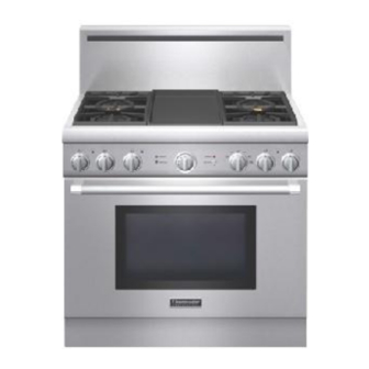
- Page 1 ERVICE ANUAL Thermador Pro Harmony® Range Model: PRL364GDH/01...
-
Page 2: Table Of Contents
Service Manual for the Thermador Pro Harmony Range, Model PRL364GDH/01 TABLE OF CONTENTS 3.3.1 Testing Cooktop Burner Ignition ..........12 3.3.1.1 Testing the HI Setting ............12 General ..................4 3.3.1.2 Testing the SIM Setting ............. 12 Technical Documents to Read Prior to Servicing ......4 3.3.1.3... - Page 3 Service Manual for the Thermador Pro Harmony Range, Model PRL364GDH/01 6.3.3 Standard Valve Removal and Replacement ......30 6.5.5 Door Removal and Installation ..........60 6.3.4 Microswitch Removal and Replacement ....... 31 6.5.5.1 Removing the Door ............60 6.3.5 Solenoid Valve Removal and Replacement ......32 6.5.5.2...
-
Page 4: General
Service Manual for the Thermador Pro Harmony Range, Model PRL364GDH/01 GENERAL 1.3 Data Rating Plate The data rating plate which shows the model, serial, and FD number This manual contains information that is necessary for servicing the is located underneath the control panel, as shown in Figure 1. This following Thermador Pro Harmony Range: information is required when calling for technical or customer service. -
Page 5: Recommended Tools And Supplies
Service Manual for the Thermador Pro Harmony Range, Model PRL364GDH/01 1.4 Recommended Tools and Supplies 1.5 Important Safety Information The following tools and supplies are recommended to use when Before starting to service an appliance, familiarize yourself with all servicing this appliance: safety information and precautions contained in this manual. - Page 6 Service Manual for the Thermador Pro Harmony Range, Model PRL364GDH/01 Testing for Gas Leaks Replacement Parts ■ Do not ever use a flame to test for gas leaks, as doing so may Use only authorized replacement parts per catalog for this appliance.
- Page 7 Service Manual for the Thermador Pro Harmony Range, Model PRL364GDH/01 In Case of Power Outage Prior to Returning Appliance to Service 1. If for any reason a control knob is on when there is any failure or Prior to returning the appliance to service, make sure that: removal of electrical power from the appliance (such as a power ■...
-
Page 8: Operation
Service Manual for the Thermador Pro Harmony Range, Model PRL364GDH/01 The knob can also be set between SIM and XLO for a variable range OPERATION of low heat, with the flame cycling on and off at a different frequency than the XLO setting (see Figure 3). -
Page 9: Temperature Selector Knob
Service Manual for the Thermador Pro Harmony Range, Model PRL364GDH/01 2.1.3 Temperature Selector Knob 2.2 Automatic Re-Ignition For each oven, use the respective Temperature Selector knob Each burner has its own electronic igniter that sparks when the burner (see Figure 5). -
Page 10: Burner Assembly And Maintop Components
Service Manual for the Thermador Pro Harmony Range, Model PRL364GDH/01 2.4 Burner Assembly and Maintop Components Ignition Hazard Do not touch burners when the igniters are active (sparking). 3.1 Before Testing Before testing the burners and ignition, do the following: 1. -
Page 11: Burner Characteristics
Service Manual for the Thermador Pro Harmony Range, Model PRL364GDH/01 3.2 Burner Characteristics If one or more burner blows out, the respective igniter electrode automatically re-ignites the flame. At each burner port the flame should burn completely around the burner cap. -
Page 12: Testing Burner Ignition
Service Manual for the Thermador Pro Harmony Range, Model PRL364GDH/01 NOTE: The air shutter for the bake burner is factory pre-set at a fully- Testing Burner Ignition opened position for all conditions, and doesn’t require adjustment. 3.3.1 Testing Cooktop Burner Ignition 3.3.3 Testing Broil Burner Ignition... -
Page 13: Burner, Flame, And Ignition Troubleshooting
Service Manual for the Thermador Pro Harmony Range, Model PRL364GDH/01 3.5 Burner, Flame, and Ignition Troubleshooting 3.5.1 Cooktop Burners – Burner and Flame Diagnostics Gas Leaks If a burner clicks (sparks) constantly, or if burner doesn’t light correctly Carefully check for gas leaks at each gas component that was... -
Page 14: Ignition Diagnostics
Service Manual for the Thermador Pro Harmony Range, Model PRL364GDH/01 Hot Burner Components Always use a pot holder to handle a hot burner cap, Venturi tube, or any other burner assembly component to prevent injury. Figure 13: Incorrect Jet Assembly-to-Maintop Alignment (Left Image) and Proper Jet Assembly-to-Maintop Position (Right Image) Figure 12: Problematic Burner –... - Page 15 Service Manual for the Thermador Pro Harmony Range, Model PRL364GDH/01 110V DC Replace No (XLO burners) into Solenoid Solenoid Valve? Valve Burner LED Is gas present 5V from No ignition Sparking? Replace Indicator is on? at burner? Potentiometer to Simmer...
-
Page 16: Oven Light Diagnostics 1
Service Manual for the Thermador Pro Harmony Range, Model PRL364GDH/01 OVEN LIGHT DIAGNOSTICS OVEN LIGHT DIAGNOSTICS 1 Make sure plunger doesn’t get stuck Turn light switch OFF and Is oven light Close oven door and Is oven light in closed position. Check wiring and then open oven door. -
Page 17: Fault Codes
Service Manual for the Thermador Pro Harmony Range, Model PRL364GDH/01 FAULT CODES When a fault is detected, this appliance will display a fault code (see Figure 20, on page 18). The fault codes are represented by the manner in which two blue LED indicators are blinking. - Page 18 Service Manual for the Thermador Pro Harmony Range, Model PRL364GDH/01 Figure 20: Fault Codes Page 18 of 68 58300000154022_ARA_EN_D...
-
Page 19: Service And Repair
Service Manual for the Thermador Pro Harmony Range, Model PRL364GDH/01 SERVICE AND REPAIR 2. Remove grates. 3. Remove all Star burner caps. 6.1 Preparing the Range for Servicing 4. Remove and retain the two T-30 screws from each brass Star burner base (see Figure 21). - Page 20 Service Manual for the Thermador Pro Harmony Range, Model PRL364GDH/01 5. While lifting the brass burner base, carefully depress the locking 6. If the electrode needs replacing, remove and retain the small T-10 tab on the female terminal of the igniter wire, and gently pull to screw to detach it from the brass burner base.
-
Page 21: Removing The Maintops
Service Manual for the Thermador Pro Harmony Range, Model PRL364GDH/01 9. Remove the following (see Figure 25): 3. Push each ignition wire downward through its respective receptacle, as you carefully lift out each maintop, in a frontward ■ Grease tray (move back, and then lift upward to remove from direction. -
Page 22: Removing The Heat Shield
Service Manual for the Thermador Pro Harmony Range, Model PRL364GDH/01 6.2.3 Removing the Heat Shield 6.2.4 Griddle Removal and Replacement The next step in accessing components under the maintop is to remove the griddle, if needed. Sharp Components – Gloves Recommended 1. - Page 23 Service Manual for the Thermador Pro Harmony Range, Model PRL364GDH/01 4. Remove support brackets (see Figure 30) by lifting the pins out of the slots on the element tray. 5. Remove the thermostat bulb by carefully pulling it out of the...
- Page 24 Service Manual for the Thermador Pro Harmony Range, Model PRL364GDH/01 7. Remove the two T-20 screws from the element tray 8. While lifting up the element tray slightly, carefully push the bulb (see Figure 33). through the circular receptacle in the element tray (see Figure 35).
-
Page 25: Burner Support Rail Removal And Replacement
Service Manual for the Thermador Pro Harmony Range, Model PRL364GDH/01 9. While removing the insulation (see Figure 36), be careful not to 6.2.5 Burner Support Rail Removal and Replacement pull on the thermostat bulb. This procedure is for the removal of the burner support rail with the jet holder assemblies attached, which may be necessary in order to gain access to components for servicing. - Page 26 Service Manual for the Thermador Pro Harmony Range, Model PRL364GDH/01 3. Using a 9/16 inch wrench, unscrew the hex nut to remove the other end of the gas tubes from their respective valve as follows: ■ [Left-side XLO valves]: While using a 1/2 inch wrench to hold the bolt on the solenoid valve, unscrew the gas tube hex nut with a 9/16 inch wrench.
-
Page 27: Removal And Replacement Of Top-Accessible Components
Service Manual for the Thermador Pro Harmony Range, Model PRL364GDH/01 6.3 Removal and Replacement of Top-Accessible -OR- Components Alternatively, use a slip joint pliers and gloves to disengage the alignment boss and rotate the jet holder assembly until it can be This section contains removal and replacement procedures for the removed (see Figure 42 and Figure 43). -
Page 28: Manifold Removal And Replacement
Service Manual for the Thermador Pro Harmony Range, Model PRL364GDH/01 5. Replace the jet holder assembly if needed. NOTE: If replacing the jet holder assembly, first install the jet holder assembly onto the burner support rail before attaching the wire guard clip. - Page 29 Service Manual for the Thermador Pro Harmony Range, Model PRL364GDH/01 8. Now remove the manifold support brackets by removing and retaining the following screws with a T-20 driver: ■ The two screws holding the manifold support bracket onto the chassis base near the regulator (see Figure 46) ■...
-
Page 30: Standard Valve Removal And Replacement
Service Manual for the Thermador Pro Harmony Range, Model PRL364GDH/01 6.3.3 Standard Valve Removal and Replacement The standard valves are for the right side burners only. 1. Follow all safety precautions and steps in Preparing the Range for Servicing, page 19. -
Page 31: Microswitch Removal And Replacement
Service Manual for the Thermador Pro Harmony Range, Model PRL364GDH/01 Gas Leaks Carefully check for gas leaks at each gas component that was removed, replaced, or otherwise serviced using a gas leak detector or bubble test. 6.3.4 Microswitch Removal and Replacement The microswitches are for the right-side burners only. -
Page 32: Solenoid Valve Removal And Replacement
Service Manual for the Thermador Pro Harmony Range, Model PRL364GDH/01 8. First make a note of how the wires (piggyback and single) are 6. First make a note of how the wires are connected to the solenoid connected to the two terminals on the microswitch, and then valve terminals, and then remove the wires from the terminals. -
Page 33: Xlo Valve Removal And Replacement
Service Manual for the Thermador Pro Harmony Range, Model PRL364GDH/01 5. Remove the burner support rail (with jet holder assemblies attached) by following the steps in Burner Support Rail Removal and Replacement, page 25. 6. First make a note of how the wires are connected to the solenoid valve terminals, and then remove the wires from the terminals. - Page 34 Service Manual for the Thermador Pro Harmony Range, Model PRL364GDH/01 12. Detach the XLO valve from the potentiometer by using a small flat-blade screwdriver to gently remove the XLO valve from the potentiometer standoffs. Then slide the potentiometer off the valve stem (see Figure 56).
-
Page 35: Potentiometer Removal And Replacement
Service Manual for the Thermador Pro Harmony Range, Model PRL364GDH/01 6.3.7 Potentiometer Removal and Replacement careful not to lose the plastic O ring positioned inside the large hex nut of the solenoid valve, as it may fall out easily The potentiometer (also known as the Simmer Control potentiometer (see Figure 53). -
Page 36: Temperature Selector Removal And Replacement
Service Manual for the Thermador Pro Harmony Range, Model PRL364GDH/01 6.3.8 Temperature Selector Removal and Replacement Figure 57: Temperature Selector and Knob NOTE: For PRL364GDH/01, the Temperature Selector may or may not be secured to the back of the control panel with a clamp. If a clamped Temperature Selector needs replacing, the replacement part (used without clamp) is fully compatible. -
Page 37: 5-Position Oven Function Selector - Removal And Replacement
Service Manual for the Thermador Pro Harmony Range, Model PRL364GDH/01 5-Position Oven Function Selector – Removal and 7. Remove clamp (if there is one) by folding the left and right clamp 6.3.9 wings up about 45 degrees (see Figure 60). -
Page 38: Dual Valve Removal And Replacement
Service Manual for the Thermador Pro Harmony Range, Model PRL364GDH/01 6.3.10 Dual Valve Removal and Replacement Caution There is one dual valve on the 36-inch range. When installing the 5-Position Oven Function Selector, make sure to attach the connector correctly onto all of the pins. -
Page 39: Regulator Removal And Replacement
Service Manual for the Thermador Pro Harmony Range, Model PRL364GDH/01 6.3.11 Regulator Removal and Replacement Gas Leaks Carefully check for gas leaks at each gas component that was Prior to Servicing the Regulator removed, replaced, or otherwise serviced using a gas leak detector or ■... -
Page 40: Ignition Device Removal And Replacement
Service Manual for the Thermador Pro Harmony Range, Model PRL364GDH/01 8. When replacing the regulator, make sure its cap fitting is facing 6.3.12 Ignition Device Removal and Replacement upward, so it can be easily accessed (see Figure 66). 1. Follow all safety precautions and steps in Preparing the Range for Servicing, page 19. -
Page 41: Control Board Removal And Replacement
Service Manual for the Thermador Pro Harmony Range, Model PRL364GDH/01 4. While pushing the protruding clip at the front end of the LED 6.3.14 Control Board Removal and Replacement indicator, push the LED indicator frontward through the hole in the 1. -
Page 42: Simmer Control Board Removal And Replacement
Service Manual for the Thermador Pro Harmony Range, Model PRL364GDH/01 6. Use a needle nose pliers to carefully remove the control board from the plastic standoffs. 7. Replace the control board only if needed. NOTE: When installing the control board, make sure the green ground wire is secured from the control board to the ground screw on the chassis. -
Page 43: Removal And Replacement Of Back-Accessible Components
Service Manual for the Thermador Pro Harmony Range, Model PRL364GDH/01 6.4 Removal and Replacement of Back-Accessible 1. Follow all safety precautions and steps in Preparing the Range for Servicing, page 19. Components 2. Remove and retain the T-20 screws on the front-facing side of the This section contains removal and replacement procedures for the backguard / Island Trim (see Figure 26, on page 21). -
Page 44: Back Panel Removal And Replacement
Service Manual for the Thermador Pro Harmony Range, Model PRL364GDH/01 Caution Be very careful not to damage the gas flex line or terminal box (junction box) components and wiring when removing or installing the back panel. 4. Carefully remove the back panel out of the right and left side guide channels, in an upward direction (see Figure 73), and detach it from the gas flex line. -
Page 45: Terminal Block Removal And Replacement
Service Manual for the Thermador Pro Harmony Range, Model PRL364GDH/01 6.4.3 Terminal Block Removal and Replacement 6.4.4 Electrical Wiring Connections at the Terminal Block Replace the terminal block (main power connector) in the event the For electrical wiring requirements and safety precautions, refer to the terminal threads are stripped, or if there is any other damage to the Installation Manual for this appliance. - Page 46 Service Manual for the Thermador Pro Harmony Range, Model PRL364GDH/01 3. From the back of the range, detach the three wire connectors (see Figure 79). Figure 80: Cooling Fan Access Holes in Chassis (Typical Range Chassis Shown) Figure 79: Wire Connectors (Typical Fan Shown) Sharp Component –...
-
Page 47: Broil Burner Assembly Removal And Replacement
Service Manual for the Thermador Pro Harmony Range, Model PRL364GDH/01 6.4.6 Broil Burner Assembly Removal and Replacement 6. From the back of the range, disconnect the hot surface igniter (HSI) blade connectors (see Figure 83). Hot Surfaces The oven broil burner and interior surfaces of the oven may be hot and can cause burns. - Page 48 Service Manual for the Thermador Pro Harmony Range, Model PRL364GDH/01 7. From inside the oven cavity, remove and retain the nut and shim ring from the right and left sides of the HSI support bracket to remove the HSI-support bracket assembly from the infrared broil burner (see Figure 85).
-
Page 49: Convection Components - Removal And Replacement
Service Manual for the Thermador Pro Harmony Range, Model PRL364GDH/01 6.4.7 Convection Components – Removal and Replacement The convection components are accessed from both the back and the front of the range. Figure 88: Elbow Connector Attached to Gas Line 13. - Page 50 Service Manual for the Thermador Pro Harmony Range, Model PRL364GDH/01 1. Follow all safety precautions and steps in Preparing the Range for Servicing, page 19. 2. Remove the backguard (see Backguard and Island Trim Removal Fiberglass and Replacement, page 43).
- Page 51 Service Manual for the Thermador Pro Harmony Range, Model PRL364GDH/01 Figure 93: Rear Cover Shield Screws Figure 95: Removing Shim Ring Figure 94: Rear Cover Shield / Motor Assembly (Back Side View) Figure 96: Screws Attaching Rear Cover Shield to Motor Bracket 11.
-
Page 52: Removal And Replacement Of Front-Accessible Components
Service Manual for the Thermador Pro Harmony Range, Model PRL364GDH/01 6.5 Removal and Replacement of Front-Accessible Components This section contains removal and replacement procedures for the components that can be accessed from the front of the range. 6.5.1 Control Panel Removal and Replacement... - Page 53 Service Manual for the Thermador Pro Harmony Range, Model PRL364GDH/01 3. Before disconnecting the wire harness connectors, first make a 6. Remove and retain the two T-20 screws from the control panel note of how they are connected to all components that are housed bracket (see Figure 99).
-
Page 54: Bake Burner Components - Removal And Replacement
Service Manual for the Thermador Pro Harmony Range, Model PRL364GDH/01 6.5.2 Bake Burner Components – Removal and Replacement Hot Surfaces The oven bake burner and interior surfaces of the oven may be hot and can cause burns. Do not service the range if these components are hot. - Page 55 Service Manual for the Thermador Pro Harmony Range, Model PRL364GDH/01 5. Detach the bottom plate of the front frame. First remove and retain Figure 104: Screws on Rim of Cavity Base the larger T-20 screws, and then remove and retain the smaller 7.
- Page 56 Service Manual for the Thermador Pro Harmony Range, Model PRL364GDH/01 Figure 106: Bake Burner with Cavity Base Removed Figure 107: Orifice Fitting Assembly 9. Detach the orifice fitting assembly from the gas flex line by using a 11. Remove and retain the two T-20 screws from the bake burner wrench to hold the small brass hex nut on the gas flex line, while bracket (see Figure 106).
- Page 57 Service Manual for the Thermador Pro Harmony Range, Model PRL364GDH/01 Figure 108: Orifice Fitting Assembly Connections Figure 109: Removing Bake Burner with HSI Attached Figure 111: Removing the HSI from the Bake Burner 13. Detach the HSI from the bake burner by removing and retaining 14.
-
Page 58: Oven Temperature Sensor Removal And Replacement
Service Manual for the Thermador Pro Harmony Range, Model PRL364GDH/01 6.5.3 Oven Temperature Sensor Removal and Replacement The oven temperature sensor is located inside the oven cavity (see Figure 112). Figure 113: Sensor Wire Connectors and Portal Figure 112: Sensor and Lamp Locations inside the Oven Cavity 1. -
Page 59: Oven Lamp Removal And Replacement
Service Manual for the Thermador Pro Harmony Range, Model PRL364GDH/01 Fiberglass Insulation Fiberglass Insulation Wear gloves when handling fiberglass insulation. Wear gloves when handling fiberglass insulation. 7. From the back of the range, while wearing gloves, clear a path in 7. -
Page 60: Door Removal And Installation
Service Manual for the Thermador Pro Harmony Range, Model PRL364GDH/01 6.5.5 Door Removal and Installation 3. Slowly open the door a few inches until it stops against the hinge locks (at about 45°). If the door doesn’t stop and can be opened... -
Page 61: Removing Door Handle Components
Service Manual for the Thermador Pro Harmony Range, Model PRL364GDH/01 Figure 116: Installing the Door Handle Components 6. Install the oven door and test for proper positioning (follow all warnings and steps for Installing the Door, page 60). 6.5.6.1 Removing Door Handle Components 6.5.7... -
Page 62: Kick Panel Removal And Replacement
Service Manual for the Thermador Pro Harmony Range, Model PRL364GDH/01 6.5.8 Kick Panel Removal and Replacement 1. Follow all safety precautions and steps in Preparing the Range for Servicing, page 19. 2. Remove oven door (see Door Removal and Installation, page 60). -
Page 63: Bottom Plate Of Front Frame - Removal And Replacement
Service Manual for the Thermador Pro Harmony Range, Model PRL364GDH/01 Bottom Plate of Front Frame – Removal and 6.5.9 Replacement 1. Follow all safety precautions and steps in Preparing the Range for Servicing, page 19. 2. Remove oven door (see Door Removal and Installation, page 60). -
Page 64: Door Hinge Receiver Removal And Replacement
Service Manual for the Thermador Pro Harmony Range, Model PRL364GDH/01 6.5.10 Door Hinge Receiver Removal and Replacement Check QuickFinder for applicable technical documents and information before replacing the door hinge receiver. Figure 125: Removing Hinge Receiver Screws 6. Using gloves, remove the hinge receiver (see Figure 126). -
Page 65: Door Hinge Removal And Replacement
Service Manual for the Thermador Pro Harmony Range, Model PRL364GDH/01 6.5.11 Door Hinge Removal and Replacement 4. Lift and remove the stainless steel door cover (see Figure 128). Check for applicable technical documents for this appliance in QuickFinder before replacing the Door Hinge. -
Page 66: Thermostat Removal And Replacement
Service Manual for the Thermador Pro Harmony Range, Model PRL364GDH/01 6.5.12 Thermostat Removal and Replacement The thermostat controls the griddle temperature. Check QuickFinder Sharp Components to order the correct Thermostat. Wear gloves when removing the door hinge 1. Follow all safety precautions and steps in the Preparing the Range for Servicing, page 19. -
Page 67: Before Returning Appliance To Service
Service Manual for the Thermador Pro Harmony Range, Model PRL364GDH/01 4. Remove the thermostat from the back of the control panel BEFORE RETURNING APPLIANCE TO SERVICE (see Figure 132). After you have finished all testing and servicing, always do the following before returning the appliance to service: ■... -
Page 68: Additional Resources
Service Manual for the Thermador Pro Harmony Range, Model PRL364GDH/01 ADDITIONAL RESOURCES 9.1 QuickFinder For further information, please refer to the following documents on QuickFinder: ■ Installation Manual ■ Care and Use Manual In addition, the following may be available on QuickFinder by visiting: http://portal.mch.bshg.com/portal...
Need help?
Do you have a question about the Pro Harmony PRL364GDH/01 and is the answer not in the manual?
Questions and answers