Table of Contents
Advertisement
Advertisement
Table of Contents

Related Manuals for Make Noise 0-Coast


Summary of Contents for Make Noise 0-Coast
- Page 1 5.19.16 REV 7 v.1.16...
-
Page 2: Table Of Contents
Circuits that Modify: --------------------------------------------------14 MIDI B: ------------------------------------------------------------------15 Signals: -------------------------------------------------------------------------16 Attenuation: ----------------------------------------------------------17 Attenuversion: -------------------------------------------------18 Control Voltage:-----------------------------------------19 The Core:------------------------------------------------------------20 The Timbre: ----------------------------------------------------------------21 SLOPE: -------------------------------------------22 Balance:--------------------------------------------------------23 The Magnitude:-------------------------------------------24-27 Beyond the Default Sound:---------------------------------------------------------28 Open Patch Points:----------------------------------------------------------------29 Overriding Normals:-------------------------------------------------------------32 Voltage Math:-------------------------------------------------------------33 Using the 0-Coast with other devices: -------------------34... -
Page 3: Fcc
(1) this device may not cause harmful interference, and (2) this device must accept any interference received, including interference that may cause undesired operation. Changes / modi cations not approved by the Make Noise Co. could void the user’s authority to operate the equipment. -
Page 4: Limited Warranty
Limited WARRANTY: Make Noise warrants this product to be free of defects in materials or construction for a period of one year from the date of purchase (proof of purchase/invoice required). Malfunction resulting from wrong power supply voltages, backwards or reversed eurorack bus board cable connection, abuse of the product or any other causes determined by Make Noise to be the fault of the user are not covered by this warranty, and normal service rates will apply. -
Page 5: Overview
The 0-COAST is a single voice patchable synthesizer. It’s name re ects the fact that it utilizes techniques from both the Moog and Buchla paradigms (aka “East Coast, ” and “West Coast, ” due to their locations), but is loyal to neither and thus implements “no coast synthesis. -
Page 6: Patch Notations
For example: As you may have guessed, this is instructing you to patch the Square Wave Output ftom the 0-Coast’s Oscillator Circuit to the External Input of the Balance Circuit. Don’t worry if it sounds daunting, you’ll quickly get the hang of it. Accompanying the written patch instructions, you’ll also nd small, visual representations of the connections. -
Page 7: User Interface
(white) knobs are used to Attenuate (i.e. “scale”) and/or Invert incoming CV. Jacks: Illuminated Buttons and Activity Windows: Every jack in the 0-Coast is either an input or an output. The 0-Coast utilizes Buttons for certain functions and behaviors and <light> Jacks are patched together with cables. Simply plug one end or <... -
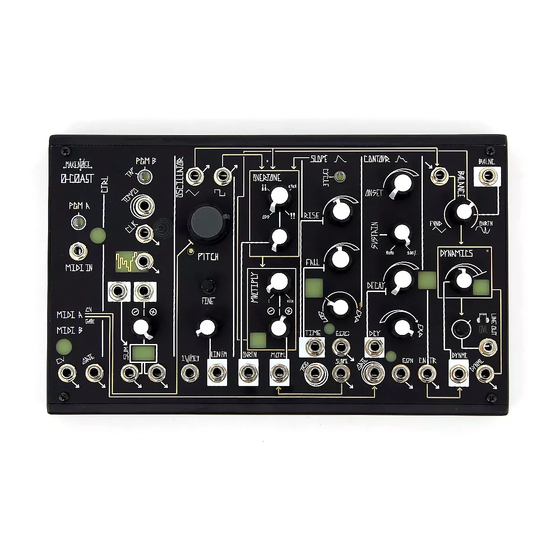
Page 8: Panel Controls
Panel Controls Figure 7: Panel Controls 18 19 12 13 38 39 17 23 24 30 40 41 49 50 51 59 60 Panel Controls: 1. PGM A Illuminated Button <white> 31. Multiply CV INput 2. MIDI A Activity Window <red> 32. -
Page 9: Default Sounds
Figure 8: Default Sound Figure 9: Drone... -
Page 10: Power
0-COAST (Figure 10). The signals inside the 0-COAST are much higher strength than typical instrument or line-level audio signals. We call these signals “Modular Level. ” For example, the OSCILLATOR Triangle OUT is a Modular Level output that has an amplitude of about 10 volts peak-to-peak, which is over 4 times “hotter”... -
Page 11: Midi And Cv/Gate Controllers
For MIDI control, use the included MIDI Adapter to plug your MIDI controller or sequencer to the MIDI Input on the 0-COAST (Figure 13). The 0-COAST defaults to receiving MIDI on ALL Channels, so you should be able to strike any key or start a sequence on your MIDI controller and see the MIDI Activity window <... -
Page 12: Program Buttons
They can be con gured to react in various ways to MIDI data. For example, the CV OUTput can be assigned to velocity, note number, mod wheel, et al. The 0-Coast also has a fun arpeggiator with two modes, an additional LFO at the MIDI B outputs, and the ability to switch between Legato and ReTrigger playing styles. - Page 13 PGM_A and PGM_B, with PGM_B <lighting> to indicate Arpeggiator = ON. • PGM_B = <OFF> – Latch & Shift = OFF (default). This is a traditional arpeggiator, which plays any held notes in the order they are played, at the 0-Coast's current Clock Rate.
- Page 14 (CONT’D) 5. MIDI B Gate Source: PGM_A = <ON>, MIDI_B = <FLASHES> • PGM_B = <OFF> – Gate goes high with Note-on • PGM_B = <ON> – Gate goes high when Velocity > 50% • PGM_B = <PULSE> – Gate goes high when Mod Wheel > 50% (default) •...
-
Page 15: Circuits That Modify
MIDI A circuit and the OSCILLATOR circuit allows for playing the Figure 18: PITCH of the 0-COAST from a MIDI controller. To hear this, rst, set 0-COAST to MIDI A CV: Normalizations the “Default Sound” (Figure 8) and then patch your MIDI controller as in Figure 14, and then play some keys or send a sequence from your MIDI controller. -
Page 16: Midi
Gate IN and DYNAMICS CV INput Jacks, the CONTOUR Signal OUT is wired to modulate DYNAMICS. In order to hear this, set 0-COAST to the “Default Sound” (Figure 8, Page 8) and play some keys or send a sequence from your MIDI controller. It is possible to re-route this wire by patching to the CONTOUR Gate IN. -
Page 17: Signals
(Figure 23). “Gate Low” is 0V (or no signal at all). There are a lot of similarities between these signal types. Keep in mind, the 0-Coast responds to like signals in similar ways. A Gate; however, is longer, anywhere from a few milliseconds to “always on. ” The length of the Gate (in time) is referred to as the Gate’s Width. -
Page 18: Attenuation
Depth of Modulation to its them with related signals, or when inverting respective parameter (more on that later) For them multiple times per cycle (see Make Noise CV Input Attenuators, such as OVERTONE, zero modDemix, “Ring Modulation. ” ) amplitude is at full counterclockwise, resulting in no modulation regardless of the signal input. -
Page 19: Attenuversion
Attenuversion An example user for the Attenuverter on the Control Processor’s CH.2 INput is patching a variable depth Vibrato. If you patch a Cycling SLOPE directly to the 1V/Oct input on the Oscillator, you get a vibrato, but with a range of many octaves. Instead, try patching it to the right input of the Control Processor, take either output to 1V/oct, and adjust the Depth using the CH. -
Page 20: Control Voltage
Using a unipolar Control Voltage like from SLOPE, it is possible to control the range and direction of modulation, in relation to the 0-Coast’s Panel Control setting, simply by adjusting the position of the associated INput Attenuvertors. For example, using the SLOPE normalization to the MULTIPLY CV INput, this has the e ect of manually rotating the Multiply Panel Control knob over time, starting with the initial Panel Control setting shown below. -
Page 21: The Core
Oscillator Set 0-COAST to the “Default Sound” (Figure 8, Page 8). To hear how the OSCILLATOR works, it is helpful to either hold a key down on your controller, or to set the 0-COAST to Drone, as shown in Figure 9. -
Page 22: The Timbre
CW, so that you are only hearing the Overtones. Hold a key on your controller or set the 0-COAST to Drone (refer to Figure 9, Page 8). Slowly turn the OVERTONE Panel Control Clockwise and listen for the change in the timbre of the sound as the single Overtone fades from ODD to... -
Page 23: Slope
MULTIPLY CV Attenuator and Panel Controls alters the way the timbre of the 0-COAST is modulated. The CV Attenuvertor is capable of adding and subtracting from the Panel Control with the “OFF” point being at 12 o’ Clock. The SLOPE and... -
Page 24: Balance
OSCILLATOR Core and are thus referred to as Overtones. To hear how the BALANCE works, rst, either hold a key down on your controller, or to set the 0-COAST to Default Drone as shown in Figure 9, Page 8. -
Page 25: The Magnitude
East Coast instruments and perhaps even Far East Coast instruments :) This combination of West Coast technique and East Coast circuitry is 0-Coast synthesis at its nest, allowing the Low Pass Gate to be used in tandem with an extremely-important East-Coast synthesis circuit: the 4-stage Envelope we call CONTOUR. - Page 26 DYNAMICS circuit, resulting in amplitude envelopes which greatly de ne the sound of the 0-COAST. This approach takes inspiration from the original Loudness Contour circuit of the MiniMoog, which is perhaps the most well-known and heavily-used example of East Coast Synthesis.
- Page 27 Clockwise in order to be more Exponential increases the rate, causing the 0-COAST to sound Figure 54: more percussive. Setting it to be more LINEAR decreases the rate, causing the 0-COAST to fade in and out of existence. EXPONENTIAL LINEAR...
- Page 28 10V peak to peak, which is more then 3 times the strength of the typical line-level audio signal commonly used in the studio and on stage. The DYNMC OUT should only be used when interfacing the 0-COAST with instruments capable of handling the large voltages produced by this type of output, such as modular synthesizers.
-
Page 29: Beyond The Default Sound
In the next section we will go into the inputs and outputs that are not normaled or hardwired, using patch cables to expand the number of connections between the circuits on the 0-Coast. This will allow for greater depth and complexity of sound. -
Page 30: Open Patch Points
Looking over the faceplate of the Using Random Out to Modulate OVERTONE: [TAP] PGM_B to change rate. 0-Coast, we will see a number of patch points that are not connected by gold wire to any others. To begin, set up the Default Sound Drone (Figure 9). - Page 31 (CONT'd) This section contains short descriptions and examples for all the connections that are not part of the gold wire signal ow of the 0-Coast. Connecting cables to these patch points has the potential to expand the capabilities of the 0-Coast, without changing anything about its default operation.
- Page 32 DYNAMICS Out: This output contains the same signal as the Line Out, but at full amplitude for connection to modular synthesizers or back into an input of the 0-Coast for feedback. It is NOT recommended to patch this output to line level...
-
Page 33: Overriding Normals
The "Open Connections" section showed the many places in which it is possible to expand your use of the 0-Coast without changing anything about its Normal operation. In this section we will show patch connections with the potential to override that operation entirely. -
Page 34: Voltage Math
Patching into a jack to override a normalization does a lot to open up the signal ow possibilities in the 0-Coast. The concepts already outlined can get you very far, but as you continue patching, some questions will eventually start to arise: What if you... -
Page 35: Using The 0-Coast With Other Devices
Using the 0 - CoAS t with Other DevIces The 0-Coast's signal inputs and outputs t the standard of the Eurorack modular synthesizer created by Doepfer. For details of this format visit http://www.doepfer.de/home_e.htm Figure: 69 Any CV or Gate signal conforming to these signal levels may be used to control the 0-Coast, and vice versa.
Need help?
Do you have a question about the 0-Coast and is the answer not in the manual?
Questions and answers