Yamaha Portatone PSR-S700 Service Manual
Hide thumbs
Also See for Portatone PSR-S700:
- Owner's manual (224 pages) ,
- Specifications (75 pages) ,
- Installation procedure (2 pages)
Advertisement
SPECIFICATIONS(総合仕様) ......................... 3/5
PANEL LAYOUT(パネルレイアウト) ................. 7
(ユニットレイアウト&結線図) .......................... 11
DISASSEMBLY PROCEDURE(分解手順) ....... 17
LSI PIN DESCRIPTION (LSI 端子機能表) ......... 29
IC BLOCK DIAGRAM (IC ブロック図) .............. 38
CIRCUIT BOARDS(シート基板図) .................. 42
TEST PROGRAM (テストプログラム) ........ 64/73
SAVING FILES (データの保存) .................... 82/83
PK
001780
PSR-S700: 20070601-131250
PSR-S900: 20070601-220500
SERVICE MANUAL
SERVICE MANUAL
(内部の設定を工場出荷時の状態に戻す) .............. 84/86
DATA BACKUP(データのバックアップ) ............ 88/90
INITIALIZING INTERNET SETTINGS
(インターネット設定の初期化) ................................. 92
SYSTEM BOOTING FLOWCHART(起動フローチャート) ....93/97
MIDI IMPLEMENTATION CHART ............................101
MIDI DATA FORMAT ................................................ 102
PARTS LIST
BLOCK DIAGRAM(ブロックダイアグラム)
CIRCUIT DIAGRAM(回路図)
Copyright (c) Yamaha Corporation. All rights reserved. PDF
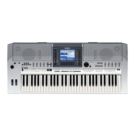
● PSR-S700
HAMAMATSU, JAPAN
'07.06
Advertisement
Chapters


Need help?
Do you have a question about the Portatone PSR-S700 and is the answer not in the manual?
Questions and answers