
Related Manuals for AMX NXA-ENET8-POE+


Summary of Contents for AMX NXA-ENET8-POE+
- Page 1 IN STR U CT IO N MAN U AL N X A - E N E T 8 - P O E + GI GABIT P OE ETHER NET SWITCH...
-
Page 2: Important Safety Instructions
COPYRIGHT NOTICE AMX© 2016, all rights reserved. No part of this publication may be reproduced, stored in a retrieval system, or transmitted, in any form or by any means, electronic, mechanical, photocopying, recording, or otherwise, without the prior written permission of AMX. Copyright protection claimed... -
Page 3: Esd Warning
Anyone performing field maintenance on AMX equipment should use an appropriate ESD field service kit complete with at least a dissipative work mat with a ground cord and a UL listed adjustable wrist strap with another ground cord. -
Page 4: Weee Notice
WEEE (recast) Directive 2012/19/EU; European Union Eco-Design Directive 2009/125/EC; European Union Registration, Evaluation, Authorization and Restriction of Chemicals (REACH) Directive 2006/121/EC You may obtain a free copy of the Declaration of Conformity by visiting http://www.amx.com/techcenter/certifications.asp. WEEE NOTICE: This appliance is labeled in accordance with European Directive 2012/19/EU concerning waste of electrical and electronic equipment (WEEE). -
Page 5: Table Of Contents
Table of Contents Table of Contents Overview ......................16 NXA-ENET8-POE+ ......................16 10/100/1000BASE-T RJ-45 Ports ....................... 16 Port Status LEDs ........................... 16 Console Port ............................16 Gigabit SFP Slots........................... 16 PoE Button ............................16 System LEDs............................16 Factory Default Button.......................... 16 Cooling Fans and Vents ........................ - Page 6 Table of Contents Quality of Service ..............................20 Address Resolution Protocol ..........................20 Multicast Filtering ............................... 20 Link Layer Discovery Protocol ..........................21 System Defaults......................21 Console Port Connection............................... 21 Authentication and Security Measures ..........................21 Web Management.................................. 21 SNMP...................................... 21 Port Configuration .................................
- Page 7 Table of Contents 10/100BASE-TX Pin Assignments ....................... 31 1000BASE-T Assignments........................31 1000BASE-T Cable Requirements........................31 Power-over-Ethernet ..........................32 Connecting to SFP Fiber Optic Ports..................... 32 Switch Management ....................... 34 Understanding the System Status LEDs ....................34 Connecting to the Console Port......................34 Resetting the Switch..........................
- Page 8 Table of Contents Configuring Summer Time........................52 Configuring the Console Port ..................54 Configuring Telnet Settings .................... 55 Displaying CPU Utilization ....................56 Configuring CPU Guard ....................56 Displaying Memory Utilization..................57 Resetting the System ...................... 58 Command Usage........................... 58 Interface Configuration ..................61 Overview .........................
- Page 9 Table of Contents VLAN Configuration ..................87 IEEE 802.1Q VLANs......................87 Assigning Ports to VLANs ........................87 Configuring VLAN Groups ........................88 Adding Static Members to VLANs ......................89 Protocol VLANs ........................ 92 Command Usage........................... 92 Configuring Protocol VLAN Groups ...................... 92 Mapping Protocol Groups to Interfaces ....................
- Page 10 Table of Contents Selecting the Queue Mode ........................120 Command Usage............................... 120 Layer 3/4 Priority Settings ................... 121 Setting Priority Processing to DSCP or CoS ..................121 Command Usage............................... 121 Mapping Ingress DSCP Values to Internal DSCP Values ..............122 Command Usage...............................
- Page 11 Table of Contents Configuring HTTPS ....................... 150 Configuring Global Settings for HTTPS ....................150 Command Usage............................... 150 Replacing the Default Secure-site Certificate ..................151 Configuring the Secure Shell ..................151 Command Usage..........................152 Configuring the SSH Server ........................ 153 Generating the Host Key Pair ......................153 Importing User Public Keys........................
- Page 12 Table of Contents DHCP Snooping VLAN Configuration ....................179 Command Usage............................... 179 Configuring Ports for DHCP Snooping ....................180 Command Usage............................... 180 Displaying DHCP Snooping Binding Information ................181 DoS Protection......................182 IPv4 Source Guard ....................... 183 Configuring Ports for IPv4 Source Guard................... 183 Command Usage...............................
- Page 13 Table of Contents Creating SNMP Notification Logs......................221 Command Usage............................... 221 Showing SNMP Statistics ........................222 Remote Monitoring....................... 223 Configuring RMON Alarms ........................223 Command Usage............................... 223 Configuring RMON Events........................225 Command Usage............................... 225 Configuring RMON History Samples ....................226 Command Usage...............................
- Page 14 Table of Contents Command Usage............................... 252 Showing MLD Snooping Groups and Source List................253 IP Tools ......................254 Using the Ping Function ....................254 Command Usage..........................254 Using the Trace Route Function ................... 255 Command Usage..........................255 Address Resolution Protocol ..................256 Displaying Dynamic or Local ARP Entries ...................
- Page 15 Table of Contents Appendix A: Software Specifications ............278 Software Features ......................278 Management Authentication ......................278 General Security Measures......................... 278 Port Configuration ..........................278 Flow Control............................278 Storm Control ............................. 278 Port Mirroring ............................. 278 Rate Limits ............................278 Port Trunking ............................278 Spanning Tree Algorithm........................
-
Page 16: Overview
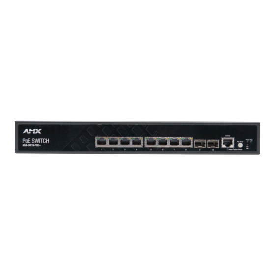
Overview Overview NXA-ENET8-POE+ The NXA-ENET8-POE+ (FG2178-64) is a Gigabit Ethernet switch with 8 10/100/1000BASE-T ports, and two Small Form Factor Pluggable (SFP) transceiver slots for fiber connectivity. The switch includes an SNMP-based management agent, which provides both in-band and out-of-band access for managing the switch. Further, the switches support both web and CLI-based configuration. -
Page 17: Cooling Fans And Vents
Overview Cooling Fans and Vents The switch must be installed in a properly cooled and ventilated environment. For more information, see the Rack Cooling section on page 26. AC Power Socket The switch requires a 100-240 VAC, 50-60 Hz AC power source. For more information on the switch power input, how to connect it, and how to power-on the switch, see the Connecting to AC Power section on page 28. -
Page 18: Web Interface
Overview Web Interface The NXA-ENET8-POE+ provides a broad range of features for Layer 2 switching and Layer 3 routing. It includes a management agent that allows you to configure the features listed in this manual. The default configuration can be used for most of the features provided by this switch. -
Page 19: Access Control Lists
Overview Description of Software Features The switch provides a wide range of advanced performance enhancing features. Flow control eliminates the loss of packets due to bottlenecks caused by port saturation. Storm suppression prevents broadcast, multicast, and unknown unicast traffic storms from engulfing the network. -
Page 20: Store-And-Forward Switching
Overview Store-and-Forward Switching The switch copies each frame into its memory before forwarding them to another port. This ensures that all frames are a standard Ethernet size and have been verified for accuracy with the cyclic redundancy check (CRC). This prevents bad frames from entering the network and wasting bandwidth. -
Page 21: Link Layer Discovery Protocol
Overview Link Layer Discovery Protocol LLDP is used to discover basic information about neighboring devices within the local broadcast domain. LLDP is a Layer 2 protocol that advertises information about the sending device and collects information gathered from neighboring network nodes it discovers. -
Page 22: Congestion Control
Overview NXA-ENET8-POE+ System Defaults (Cont.) Function Parameter Default Congestion Control Rate Limiting Disabled Storm Control Broadcast: Enabled (64kbits/sec) Multicast: Disabled Unknown Unicast: Disabled Address Table Aging Time 300 seconds Spanning Tree Algorithm Status Enabled, RSTP (Defaults: RSTP standard) Edge Ports Auto LLDP Status... -
Page 23: Installation
NOTE: Other documentation including the Quick Start Guide and CLI Reference Guide can be accessed on the NXA-ENET8-POE+ product page at www.amx.com. Switch Installation Tasks Follow these tasks to install the switch in your network. For full details on each task, go to the relevant chapter or section by clicking on the link. -
Page 24: Connect Ac Power To Power On
Installation Connect AC Power to Power On Prior to connecting to AC power, assure to connect the chassis ground connection to a known earth ground. Connect the power cord to the AC socket on the switch and to a grounded, 3-pin, AC power source. See the Power and Grounding section on page 28 for more information. -
Page 25: Through The Console Port
Installation Through the Console Port The serial port's configuration requirements are as follows: 115200 bps, 8 characters, no parity, one stop bit, 8 data bits, and no flow control. You can log in to the command-line interface (CLI) using default settings: User "admin" with password "admin". See the Connecting to the Console Port section on page 34 for more information. -
Page 26: Switch Cooling Requirements
Installation Switch Cooling Requirements Wherever the switch is located, be sure to pay close attention to switch cooling requirements. The location should be well ventilated and provide unrestricted airflow at the front, back, and sides of the switch. If the airflow is insufficient, it may cause the switch to overheat and possibly fail. -
Page 27: Rack-Mounting The Switch
Installation Rack-Mounting the Switch Before you start to rack-mount the switch, be sure to have the following items available: Four mounting screws for each device you plan to install in a rack-these are not included. Be sure to use the rack mounting ... -
Page 28: Power And Grounding
Installation Power and Grounding The following sections provide details on how to connect AC power to the switch, grounding the chassis, and how to power-on the switch. Switch Power Supply The switch requires power from an external AC power supply that can meet the required specification described below. Active power requirements: AC Input Power: 100-240V, 50-60Hz, 2.1A ... -
Page 29: Port Connections
Installation Port Connections This section provides details on making connections to switch network interfaces, including how to install optional transceivers, and details on network cable specifications. Cable Labeling and Connection Records When planning a network installation, it is essential to label the opposing ends of cables and to record where each cable is connected. -
Page 30: Connecting To Twisted-Pair Copper Ports
Installation Perform the following steps to install an SFP transceiver: Consider network and cabling requirements to select an appropriate transceiver type that is also compatible with the switch transceiver support. If the SFP slot is covered with a rubber protective cap, remove the cap and keep it for later replacement. Insert the transceiver with the optical connector facing outward and the slot connector facing down. -
Page 31: 10/100Base-Tx Pin Assignments
Installation 10/100BASE-TX Pin Assignments All 100BASE-TX RJ-45 ports support automatic MDI/MDI-X operation, so you can use straight-through or crossover cables for all network connections to PCs, switches, or hubs. In straight-through cable, pins 1, 2, 3, and 6, at one end of the cable, are connected straight through to pins 1, 2, 3, and 6 at the other end of the cable. -
Page 32: Power-Over-Ethernet
Installation Power-over-Ethernet The PoE switch supports both IEEE 802.3af and IEEE 802.3at-2009 PoE standards. These switches are excellent choices for supplying power to connected PoE devices such as web cameras, IP telephones, or access points. NXA-ENET8-POE+ PoE Power Budget Total PoE Power Budget 125W Ports supply up to 15.4W simultaneously... - Page 33 Installation Follow these steps to connect cables to SFP transceiver ports: WARNING: This switch uses lasers to transmit signals over f iber optic cable. The lasers are compliant with the requirements of a Class 1 Laser Product and are inherently eye safe in normal operation. However, you should never look directly at a transmit port when it is powered on.
-
Page 34: Switch Management
Installation Switch Management The switches include a management agent that allows you to configure or monitor the switch using its embedded management software. To manage the switch, you can make a direct connection to the console port (out-of-band), or you can manage it through a network connection (in-band) using Telnet, Secure Shell (SSH), a web browser, or SNMP-based network management software. - Page 35 Installation The following table describes the pin assignments used in the console cable: Console Cable Wiring Switch’s RJ-45 Console Port Null Modem PC’s 9-Pin DTE Port 6 RXD (receive data) <----------------- 3 TXD (transmit data) 3 TXD (transmit data) ------------------> 2 RXD (receive data) 4, 5 SGND (signal ground) -------------------...
-
Page 36: Resetting The Switch
Installation Resetting the Switch The Reset button located on the front right side panel of the switch can be used to restart the device and set the configuration back to either the currently saved configuration or the factory default settings. Resetting to the Saved Conf iguration File Press the Reset button for less than 5 seconds to restart the system software using the current saved configuration file settings. -
Page 37: Using The Web Interface
Information, Port Utilization, Dynamic Address Count, and LLDP Remote Device Port List are displayed on the right side. The main menu links are used to navigate to other menus, and display configuration parameters and statistics. Dashboard FIG. 20 NOTE: You can open a connection to the vendor's web site by clicking the AMX logo. Instruction Manual - NXA-ENET8-POE+... -
Page 38: Home Page
Home Page FIG. 21 NOTE: You can open a connection to the vendor's web site by clicking the AMX logo. Conf iguration Options Configurable parameters have a dialog box or a drop-down list. Once a configuration change has been made on a page, be sure to click on the Apply button to confirm the new setting. -
Page 39: Basic Management Tasks
Basic Management Tasks Basic Management Tasks Overview This chapter describes the following topics: Displaying System Information - Provides basic system description, including contact information. Displaying Hardware/Software Versions - Shows the hardware version, power status, and firmware versions Conf iguring Support for Jumbo Frames - Enables support for jumbo frames. ... -
Page 40: Hardware/Software Versions
Basic Management Tasks Hardware/Software Versions Use the System > Switch page to display hardware/firmware version numbers for the main board and management software, as well as the power status of the system. The following table lists the options on this page. The options on this page on view-only. System - Switch Options Main Board Information Serial Number... -
Page 41: Configuring Support For Jumbo Frames
Basic Management Tasks Conf iguring Support for Jumbo Frames Use the System > Capability page to configure support for layer 2 jumbo frames. The switch provides more efficient throughput for large sequential data transfers by supporting jumbo frames up to 10240 bytes for Gigabit Ethernet and 10 Gigabit Ethernet ports or trunks. -
Page 42: System Files
Basic Management Tasks To view Bridge Extension information, click System, then Capability. Displaying Bridge Extension Configuration FIG. 26 System Files This section describes how to upgrade the switch operating software or configuration files, and set the system start-up files. Copying Files via FTP/TFTP or HTTP Use the System >... -
Page 43: Saving The Running Configuration To A Local File
Basic Management Tasks Enter the name of the file to download. Select a file on the switch to overwrite or specify a new file name. Click Apply. Copy Firmware FIG. 27 If you replaced a file currently used for startup and want to start using the new file, reboot the system via the System > Reset menu. -
Page 44: Setting The Start-Up File
Basic Management Tasks Setting the Start-up File Use the System > File (Set Start-Up) page to specify the firmware or configuration file to use for system initialization. Perform these steps to set a file to use for system initialization: Click System > File. Select Set Start-Up from the Action list. -
Page 45: Automatic Operation Code Upgrade
Basic Management Tasks Automatic Operation Code Upgrade Use the System > File (Automatic Operation Code Upgrade) page to automatically download an operation code file when a file newer than the currently installed one is discovered on the file server. After the file is transferred from the server and successfully written to the file system, it is automatically set as the startup file, and the switch is rebooted. - Page 46 Basic Management Tasks The following parameters are displayed: System - File Options Automatic Opcode Upgrade Enables the switch to search for an upgraded operation code file during the switch bootup process. By default, this option is disabled. Automatic Upgrade Location URL Defines where the switch should search for the operation code upgrade file.
-
Page 47: Setting The System Clock
Basic Management Tasks Perform these steps to configure automatic code upgrade: Click System > File. Select Automatic Operation Code Upgrade from the Action list. Mark the check box to enable Automatic Opcode Upgrade. Enter the URL of the FTP or TFTP server, and the path and directory containing the operation code. Click Apply. -
Page 48: Setting The Sntp Polling Interval
Basic Management Tasks Perform these steps to manually set the system clock: Click System > Time. Select Conf igure General from the Step list. Select Manual from the Maintain Type list. Enter the time and date in the appropriate fields. Click Apply. -
Page 49: Configuring Ntp
Basic Management Tasks Conf iguring NTP Use the System > Time (Configure General - NTP) page to configure NTP authentication and show the polling interval at which the switch will query the specified time servers. The following table displays the options on this page: System - Time Options Current Time Shows the current time set on the switch. -
Page 50: Specifying Ntp Time Servers
Basic Management Tasks Perform these steps to set the SNTP time servers: Click System > Time. Select Conf igure Time Server from the Step list. Select Conf igure SNTP Server from the Action list. Enter the IP address of up to three time servers. Click Apply. -
Page 51: Specifying Ntp Authentication Keys
Basic Management Tasks Specifying NTP Authentication Keys Use the System > Time (Configure Time Server - Add NTP Authentication Key) page to add an entry to the authentication key list. The following table displays the options on this page: System - Time Options Authentication Key Specifies the number of the key in the NTP Authentication Key List to use for authentication with a configured server. -
Page 52: Setting The Time Zone
Basic Management Tasks Setting the Time Zone Use the System > Time (Configure Time Zone) page to set the time zone. SNTP uses Coordinated Universal Time (or UTC, formerly Greenwich Mean Time, or GMT) based on the time at the Earth's prime meridian, zero degrees longitude, which passes through Greenwich, England. - Page 53 Basic Management Tasks The following table displays the options on this page: System - Time Options General Conf iguration Summer Time in Effect Shows if the system time has been adjusted. Status Shows if summer time is set to take effect during the specified period. Name Name of the time zone while summer time is in effect, usually an acronym.
-
Page 54: Configuring The Console Port
Basic Management Tasks Conf iguring the Console Port Use the System > Console menu to configure connection parameters for the switch's console port. You can access the on-board configuration program by attaching a VT100 compatible device to the switch's serial console port. Management access through the console port is controlled by various parameters, including a password (only configurable through the CLI), time outs, and basic communication settings. -
Page 55: Configuring Telnet Settings
Basic Management Tasks Conf iguring Telnet Settings Use the System > Telnet menu to configure parameters for accessing the CLI over a Telnet connection. You can access the on-board configuration program over the network using Telnet (i.e., a virtual terminal). Management access via Telnet can be enabled/disabled and other parameters set, including the TCP port number, time outs, and a password. -
Page 56: Displaying Cpu Utilization
Basic Management Tasks Displaying CPU Utilization Use the System > CPU Utilization page to display information on CPU utilization. The following table displays the options on this page: System - CPU Utilization Options Time Interval The interval at which to update the displayed utilization rate. (Options: 1, 5, 10, 30, 60 seconds; Default: 1 second) CPU Utilization CPU utilization over specified interval... -
Page 57: Displaying Memory Utilization
Basic Management Tasks Perform these steps to configure CPU Guard: Click System > CPU Guard. Set CPU guard status, configure the watermarks or threshold parameter, enable traps if required. Click Apply. Configuring CPU Guard FIG. 45 Displaying Memory Utilization Use the System > Memory Status page to display memory utilization parameters. The following table displays the options on this page: System - Memory Status Options Free Size... -
Page 58: Resetting The System
Basic Management Tasks Resetting the System Use the System > Reset menu to restart the switch immediately, at a specified time, after a specified delay, or at a periodic interval. Command Usage This command resets the entire system. When the system is restarted, it will always run the Power-On Self-Test. It will also retain all configuration information ... - Page 59 Basic Management Tasks Perform these steps to restart the switch: Click System > Reset. Select the required reset mode. For any option other than to reset immediately, fill in the required parameters Click Apply. When prompted, confirm that you want reset the switch. Restarting the Switch (Immediately) FIG.
- Page 60 Basic Management Tasks Restarting the Switch (Regularly) FIG. 50 Instruction Manual - NXA-ENET8-POE+...
-
Page 61: Interface Configuration
Interface Configuration Interface Conf iguration Overview This chapter describes the following topics: Port Conf iguration - Configures connection settings, including auto- negotiation, or manual setting of speed, duplex mode, and flow control. Displaying Statistics - Shows Interface, Etherlike, and RMON port statistics in table or chart form. ... -
Page 62: Configuring By Port Range
Interface Configuration Interface - Port (General) Options Flow Control Allows automatic or manual selection of flow control. (Default: Enabled) Link Up Link Down Issues a notification message whenever a port link is established or broken. (Default: Disabled) Perform these steps to configure port connection parameters: Click Interface >... -
Page 63: Displaying Connection Status
Interface Configuration Displaying Connection Status Use the Interface > Port > General (Show Information) page to display the current connection status, including link state, speed/duplex mode, flow control, and auto- negotiation. The following table lists the options on this page: Interface - General (Show Information) Options Port Port identifier. - Page 64 Interface Configuration Port Statistics Transmitted Discarded Packets The number of outbound packets which were chosen to be discarded even though no errors had been detected to prevent their being transmitted. One possible reason for discarding such a packet could be to free up buffer space. Received Multicast Packets The number of packets, delivered by this sub-layer to a higher sub-layer, which were addressed to a multicast address at this sub-layer.
- Page 65 Interface Configuration Port Statistics 65-127 Byte Packets The total number of packets (including bad packets) received and transmitted where the number of octets fall within the specified range (excluding framing bits but including FCS octets). 128-255 Byte Packets 256-511 Byte Packets 512-1023 Byte Packets 1024-1518 Byte Packets 1519-1536 Byte Packets...
-
Page 66: Displaying Statistical History
Interface Configuration If Interface, Etherlike, RMON statistics mode is chosen, select a port from the drop-down list. If All (ports) statistics mode is chosen, select the statistics type to display. Showing Port Statistics (Chart) FIG. 55 Displaying Statistical History Use the Interface > Port > History or Interface > Trunk > History page to display statistical history for the specified interfaces. Command Usage For a description of the statistics displayed on these pages, see the Showing Port or Trunk Statistics section on page 63. - Page 67 Interface Configuration Interface - History Options Mode • Status - Shows the sample parameters. • Current Entry - Shows current statistics for the specified port and named sample. • Input Previous Entries - Shows statistical history for ingress traffic. • Output Previous Entries - Shows statistical history for egress traffic. Port Port number (Range: 1-10/28) Name...
- Page 68 Interface Configuration Perform these steps to show the configured parameters for a sampling entry: Click Interface > Port > Statistics, or Interface > Trunk > Statistics. Select Show Details from the Action menu. Select Status from the options for Mode. Select an interface from the Port or Trunk list.
-
Page 69: Displaying Transceiver Data
Interface Configuration Displaying Transceiver Data Use the Interface > Port > Transceiver page to display identifying information, and operational for optical transceivers which support Digital Diagnostic Monitoring (DDM). The following table lists the options on this page: Interface - Transceiver Options Port Port number. - Page 70 Interface Configuration Interface - Transceiver Options DDM Thresholds Information on alarm and warning thresholds. The switch can be configured to send a trap when the measured parameter falls outside of the specified thresholds. The following alarm and warning parameters are supported: •...
-
Page 71: Trunk Configuration
Interface Configuration Trunk Conf iguration This section describes how to configure static and dynamic trunks. You can create multiple links between devices that work as one virtual, aggregate link. A port trunk offers a dramatic increase in bandwidth for network segments where bottlenecks exist, as well as providing a fault-tolerant link between two devices. You can create up to 16 trunks at a time on the switch, or up to 32 across the stack. - Page 72 Interface Configuration The following table lists the options on this page: Interface - Static Trunk Options Trunk ID Trunk identifier (Range: 1-8) Member The initial trunk member. Use the Add Member page to configure additional members. Unit Unit identifier (Range: 1) Port Port identifier (Range: 1-10/26/28/52) Perform these steps to create a static trunk:...
-
Page 73: Configuring A Dynamic Trunk
Interface Configuration Perform these steps to display trunk connection parameters: Click Interface > Trunk > Static. Select Conf igure General from the Step list. Select Show Information from the Action list. Showing Information for Static Trunks FIG. 66 Conf iguring a Dynamic Trunk Use the Interface >... - Page 74 Interface Configuration Interface - Static Trunk Options Timeout Mode The timeout to wait for the next LACP data unit (LACPDU): • Long Timeout - Specifies a slow timeout of 90 seconds. (This is the default setting.) • Short Timeout - Specifies a fast timeout of 3 seconds. The timeout is set in the LACP timeout bit of the Actor State field in transmitted LACPDUs.
- Page 75 Interface Configuration Perform these steps to configure the admin key for a dynamic trunk: Click Interface > Trunk > Dynamic. Select Conf igure Aggregator from the Step list. Set the Admin Key and timeout mode for the required LACP group. Click Apply.
-
Page 76: Displaying Lacp Port Counters
Interface Configuration Perform these steps to show the active members of a dynamic trunk: Click Interface > Trunk > Dynamic. Select Conf igure Trunk from the Step list. Select Show Member from the Action list. Select a Trunk. Showing Members of a Dynamic Trunk FIG. -
Page 77: Displaying Lacp Settings And Status For The Local Side
Interface Configuration Perform these steps to display LACP port counters: Click Interface > Trunk > Dynamic. Select Conf igure Aggregation Port from the Step list. Select Show Information from the Action list. Click Counters. Select a group member from the Port list. Displaying LACP Port Counters FIG. -
Page 78: Displaying Lacp Settings And Status For The Remote Side
Interface Configuration Perform these steps to display LACP settings and status for the local side: Click Interface > Trunk > Dynamic. Select Conf igure Aggregation Port from the Step list. Select Show Information from the Action list. Click Internal. Select a group member from the Port list. Displaying LACP Port Internal Information FIG. -
Page 79: Configuring Load Balancing
Interface Configuration Perform these steps to display LACP settings and status for the remote side: Click Interface > Trunk > Dynamic. Select Conf igure Aggregation Port from the Step list. Select Show Information from the Action list. Click Neighbors. Select a group member from the Port list. Displaying LACP Port Remote Information FIG. -
Page 80: Saving Power
Interface Configuration Perform these steps to display the load-distribution method used by ports in aggregated links: Click Interface > Trunk > Load Balance. Select the required method from the Load Balance Mode list. Click Apply. Configuring Load Balancing FIG. 77 Saving Power Use the Interface >... -
Page 81: Configuring Local Port Mirroring
Interface Configuration Conf iguring Local Port Mirroring Use the Interface > Mirror page to mirror traffic from any source port to a target port for real-time analysis. You can then attach a logic analyzer or RMON probe to the target port and study the traffic crossing the source port in a completely unobtrusive manner. Command Usage Traffic can be mirrored from one or more source ports to a destination port on the same switch (local port mirroring as ... -
Page 82: Configuring Remote Port Mirroring
Interface Configuration Conf iguring Remote Port Mirroring Use the Interface > RSPAN page to mirror traffic from remote switches for analysis at a destination port on the local switch. This feature, also called Remote Switched Port Analyzer (RSPAN), carries traffic generated on the specified source ports for each session over a user-specified VLAN dedicated to that RSPAN session in all participating switches. - Page 83 Interface Configuration The following table lists the options on this page: Remote Port Mirroring Options Session A number identifying this RSPAN session. (Range: 1-3) Three sessions are allowed, including both local and remote mirroring, using different VLANs for RSPAN sessions. Operation Status Indicates whether or not RSPAN is currently functioning.
-
Page 84: Traffic Segmentation
Interface Configuration Configuring Remote Port Mirroring (Intermediate) FIG. 83 Configuring Remote Port Mirroring (Destination) FIG. 84 Traff ic Segmentation If tighter security is required for passing traffic from different clients through downlink ports on the local network and over uplink ports to the service provider, port-based traffic segmentation can be used to isolate traffic for individual clients. -
Page 85: Configuring Uplink And Downlink Ports
Interface Configuration Conf iguring Uplink and Downlink Ports Use the Interface > Traffic Segmentation (Configure Session) page to assign the downlink and uplink ports to use in the segmented group. Ports designated as downlink ports can not communicate with any other ports on the switch except for the uplink ports. Uplink ports can communicate with any other ports on the switch and with any designated downlink ports. - Page 86 Interface Configuration Perform these steps to show the members of the traffic segmentation group: Click Interface > Traff ic Segmentation. Select Conf igure Session from the Step list. Select Show from the Action list. Showing Traffic Segmentation Members FIG. 87 Instruction Manual - NXA-ENET8-POE+...
-
Page 87: Vlan Configuration
VLAN Configuration VLAN Conf iguration This chapter includes the following topics: IEEE 802.1Q VLANs - Configures static and dynamic VLANs. Protocol VLANs* - Configures VLAN groups based on specified protocols. MAC-based VLANs* - Maps untagged ingress frames to a specified VLAN if the source MAC address is found in the IP MAC ... -
Page 88: Configuring Vlan Groups
VLAN Configuration Untagged VLANs - Untagged VLANs are typically used to reduce broadcast traffic and to increase security. A group of network users assigned to a VLAN form a broadcast domain that is separate from other VLANs configured on the switch. Packets are forwarded only between ports that are designated for the same VLAN. -
Page 89: Adding Static Members To Vlans
VLAN Configuration Perform these steps to modify the configuration settings for VLAN groups: Click VLAN > Static. Select Modify from the Action list. Select the identifier of a configured VLAN. Modify the VLAN name or operational status as required. Enable the L3 Interface field to specify that a VLAN will be used as a Layer 3 interface. Click Apply. - Page 90 VLAN Configuration VLAN - Static Options Ingress Filtering Determines how to process frames tagged for VLANs for which the ingress port is not a member. (Default: Enabled) • Ingress filtering only affects tagged frames. • If ingress filtering is disabled and a port receives frames tagged for VLANs for which it is not a member, these frames will be flooded to all other ports (except for those VLANs explicitly forbidden on this port).
- Page 91 VLAN Configuration Perform these steps to configure static members by interface: Click VLAN > Static. Select Edit Member by Interface from the Action list. Select a port or trunk configure. Modify the settings for any interface as required. Click Apply. Configuring Static VLAN Members by Interface FIG.
-
Page 92: Protocol Vlans
VLAN Configuration Protocol VLANs The network devices required to support multiple protocols cannot be easily grouped into a common VLAN. This may require non-standard devices to pass traffic between different VLANs in order to encompass all the devices participating in a specific protocol. -
Page 93: Mapping Protocol Groups To Interfaces
VLAN Configuration Perform these steps to configure a protocol group: Click VLAN > Protocol. Select Conf igure Protocol from the Step list. Select Show from the Action list. Displaying Protocol VLANs FIG. 96 Mapping Protocol Groups to Interfaces Use the VLAN > Protocol (Configure Interface - Add) page to map a protocol group to a VLAN for each interface that will participate in the group. -
Page 94: Configuring Mac-Based Vlans
VLAN Configuration Perform these steps to show the protocol groups mapped to a port or trunk: Click VLAN > Protocol. Select Conf igure Interface from the Step list. Select Show from the Action list. Select a port or trunk. Showing the Interface to Protocol Group Mapping FIG. - Page 95 VLAN Configuration Perform these steps to map a MAC address to a VLAN: Click VLAN > MAC-Based. Select Add from the Action list. Enter an address in the MAC Address field, and a mask to indicate a range of addresses if required. Enter an identifier in the VLAN field.
-
Page 96: Address Table Settings
Address Table Settings Address Table Settings Switches store the addresses for all known devices. This information is used to pass traffic directly between the inbound and outbound ports. All the addresses learned by monitoring traffic are stored in the dynamic address table. You can also manually configure static addresses that are bound to a specific port. -
Page 97: Setting Static Addresses
Address Table Settings Setting Static Addresses Use the MAC Address > Static page to configure static MAC addresses. A static address can be assigned to a specific interface on this switch. Static addresses are bound to the assigned interface and will not be moved. When a static address is seen on another interface, the address will be ignored and will not be written to the address table. -
Page 98: Changing The Aging Time
Address Table Settings Changing the Aging Time Use the MAC Address > Dynamic (Configure Aging) page to set the aging time for entries in the dynamic address table. The aging time is used to age out dynamically learned forwarding information. The following table lists the options on this page: MAC Address - Dynamic Options Aging Status... -
Page 99: Clearing The Dynamic Address Table
Address Table Settings Perform these steps to show the dynamic address table: Click MAC Address > Dynamic. Select Show Dynamic MAC from the Action list. Select the Sort Key (MAC Address, VLAN, or Interface). Enter the search parameters (MAC Address, VLAN, or Interface). Click Query. -
Page 100: Issuing Mac Address Traps
Address Table Settings Issuing MAC Address Traps Use the MAC Address > MAC Notification pages to send SNMP traps (i.e., SNMP notifications) when a dynamic MAC address is added or removed. The following table lists the options on this page: MAC Address - MAC Notif ication Options Conf igure Global MAC Notification Traps... -
Page 101: Spanning Tree Algorithm
Spanning Tree Algorithm Spanning Tree Algorithm This chapter describes the following basic topics: Loopback Detection - Configures detection and response to loopback BPDUs. Global Settings for STA - Configures global bridge settings for STP, RSTP and MSTP. Interface Settings for STA - Configures interface settings for STA, including priority, path cost, link type, and designation ... - Page 102 Spanning Tree Algorithm MSTP - When using STP or RSTP, it may be difficult to maintain a stable path between all VLAN members. Frequent changes in the tree structure can easily isolate some of the group members. MSTP (which is based on RSTP for fast convergence) is designed to support independent spanning trees based on VLAN groups.
-
Page 103: Configuring Loopback Detection
Spanning Tree Algorithm Conf iguring Loopback Detection Use the Spanning Tree > Loopback Detection page to configure loopback detection on an interface. When loopback detection is enabled and a port or trunk receives its own BPDU, the detection agent drops the loopback BPDU, sends an SNMP trap, and places the interface in discarding mode. -
Page 104: Configuring Global Settings For Sta
Spanning Tree Algorithm Conf iguring Global Settings for STA Use the Spanning Tree > STA (Configure Global - Configure) page to configure global settings for the spanning tree that apply to the entire switch. Command Usage Spanning Tree Protocol* - This option uses RSTP set to STP forced compatibility mode. It uses RSTP for the internal state ... - Page 105 Spanning Tree Algorithm Spanning Tree - STA Options When the Switch Becomes Root Hello Time Interval (in seconds) at which the root device transmits a configuration message. • Default: 2 • Minimum: 1 • Maximum: The lower of 10 or [(Max. Message Age / 2) -1] Maximum Age The maximum time (in seconds) a device can wait without receiving a configuration message before attempting to reconverge.
- Page 106 Spanning Tree Algorithm Perform these steps to configure global STA settings: Click Spanning Tree, STA. Select Conf igure Global from the Step list. Select Conf igure from the Action list. Modify any of the required attributes. Note that the parameters displayed for the spanning tree types (STP, RSTP, MSTP) varies as described in the preceding section.
-
Page 107: Displaying Global Settings For Sta
Spanning Tree Algorithm Configuring Global Settings for STA (MSTP) FIG. 115 Displaying Global Settings for STA Use the Spanning Tree > STA (Configure Global - Show Information) page to display a summary of the current bridge STA information that applies to the entire switch. The following table lists the options on this page: Spanning Tree - STA Options Bridge ID... -
Page 108: Configuring Interface Settings For Sta
Spanning Tree Algorithm Conf iguring Interface Settings for STA Use the Spanning Tree > STA (Configure Interface - Configure) page to configure RSTP and MSTP attributes for specific interfaces, including port priority, path cost, link type, and edge port. You may use a different priority or path cost for ports of the same media type to indicate the preferred path, link type to indicate a point-to- point connection or shared-media connection, and edge port to indicate if the attached device can support fast forwarding. - Page 109 Spanning Tree Algorithm Spanning Tree - STA Options Admin Edge Port Since end nodes cannot cause forwarding loops, they can pass directly through to the spanning tree forwarding state. Specifying Edge Ports provides quicker convergence for devices such as workstations or servers, retains the current forwarding database to reduce the amount of frame flooding required to rebuild address tables during reconfiguration events, does not cause the spanning tree to initiate reconfiguration when the interface changes state, and also overcomes other STA-related timeout problems.
- Page 110 Spanning Tree Algorithm Default STA Path Costs Port Type Short Path Cost Long Path Cost (IEEE 802.1D-1998) (IEEE 802.1D-2004) Ethernet 65,535 1,000,000 Fast Ethernet 65,535 100,000 Gigabit Ethernet 10,000 10,000 10G Ethernet 1,000 1,000 Administrative path cost cannot be used to directly determine the root port on a switch. Connections to other devices use IEEE 802.1Q-2005 to determine the root port as in the following example.
-
Page 111: Displaying Interface Settings For Sta
Spanning Tree Algorithm Displaying Interface Settings for STA Use the Spanning Tree > STA (Configure Interface - Show Information) page to display the current status of ports or trunks in the Spanning Tree. The following table lists the options on this page: Spanning Tree - STA Options Spanning Tree Shows if STA has been enabled on this interface. - Page 112 Spanning Tree Algorithm Alternate port receives more R: Root Port useful BPDUs from another A: Alternate Port bridge and is therefore not D: Designated Port selected as the designated B: Backup Port port. Backup port receives more useful BPDUs from the use bridge and is therefore not selected as the designated port.
-
Page 113: Configuring Multiple Spanning Trees
Spanning Tree Algorithm Conf iguring Multiple Spanning Trees Use the Spanning Tree > MSTP (Configure Global) page to create an MSTP instance, or to add VLAN groups to an MSTP instance. Command Usage MSTP generates a unique spanning tree for each instance. This provides multiple pathways across the network, thereby balancing the traffic load, preventing wide- scale disruption when a bridge node in a single instance fails, and allowing for faster convergence of a new topology for the failed instance. - Page 114 Spanning Tree Algorithm Perform these steps to modify the priority for an MST instance: Click Spanning Tree > MSTP. Select Conf igure Global from the Step list. Select Modify from the Action list. Modify the priority for an MSTP Instance. Click Apply.
-
Page 115: Configuring Interface Settings For Mstp
Spanning Tree Algorithm Perform these steps to show the VLAN members of an MSTP instance: Click Spanning Tree > MSTP. Select Conf igure Global from the Step list. Select Show Member from the Action list. Displaying Members of an MST Instance FIG. - Page 116 Spanning Tree Algorithm Perform these steps to configure MSTP parameters for a port or trunk: Click Spanning Tree > MSTP. Select Conf igure Interface from the Step list. Select Conf igure from the Action list. Enter the priority and path cost for an interface Click Apply.
-
Page 117: Congestion Control
Congestion Control Congestion Control The switch can set the maximum upload or download data transfer rate for any port. It can also control traffic storms by setting a maximum threshold for broadcast traffic or multicast traffic. It can also set bounding thresholds for broadcast and multicast storms which can be used to automatically trigger rate limits or to shut down a port. -
Page 118: Storm Control
Congestion Control Storm Control Use the Traffic > Storm Control page to configure broadcast, multicast, and unknown unicast storm control thresholds. Traffic storms may occur when a device on your network is malfunctioning, or if application programs are not well designed or properly configured. -
Page 119: Class Of Service
Class of Service Class of Service Class of Service (CoS) allows you to specify which data packets have greater precedence when traffic is buffered in the switch due to congestion. This switch supports CoS with eight priority queues for each port. Data packets in a port's high-priority queue will be transmitted before those in the lower-priority queues. -
Page 120: Selecting The Queue Mode
Class of Service Selecting the Queue Mode Use the Traffic > Priority > Queue page to set the queue mode for the egress queues on any interface. The switch can be set to service the queues based on a strict rule that requires all traffic in a higher priority queue to be processed before the lower priority queues are serviced, or Weighted Round-Robin (WRR) queuing which specifies a scheduling weight for each queue. -
Page 121: Layer 3/4 Priority Settings
Class of Service Setting the Queue Mode (WRR) FIG. 133 Setting the Queue Mode (Strict and WRR) FIG. 134 Layer 3/4 Priority Settings The switch supports several common methods of prioritizing layer 3/4 traffic to meet application requirements. Traffic priorities can be specified in the IP header of a frame, using the priority bits in the Type of Service (ToS) octet, or the number of the TCP/ UDP port. -
Page 122: Mapping Ingress Dscp Values To Internal Dscp Values
Class of Service Perform these steps to configure the trust mode: Click Traff ic > Priority > Trust Mode. Set the trust mode for any port. Click Apply. Setting the Trust Mode FIG. 135 Mapping Ingress DSCP Values to Internal DSCP Values Use the Traffic >... -
Page 123: Mapping Cos Priorities To Internal Dscp Values
Class of Service Perform these steps to map DSCP values to internal PHB/drop precedence: Click Traff ic > Priority > DSCP to DSCP. Select Conf igure from the Action list. Select the port to configure. Set the PHB and drop precedence for any DSCP value. Click Apply. - Page 124 Class of Service Default Mapping of CoS/CFI to Internal PHB/Drop Precedence (0,0) (0,0) (1,0) (1,0) (2,0) (2,0) (3,0) (3,0) (4,0) (4,0) (5,0) (5,0) (6,0) (6,0) (7,0) (7,0) Perform these steps to map CoS/CFI values to internal PHB/drop precedence: Click Traff ic > Priority > CoS to DSCP. Select Conf igure from the Action list.
-
Page 125: Quality Of Service
Quality of Service Quality of Service This chapter describes the following tasks required to apply QoS policies: Class Map - Creates a map which identifies a specific class of traffic. Policy Map - Sets the boundary parameters used for monitoring inbound traffic, and the action to take for conforming and ... - Page 126 Quality of Service Traff ic - Diffserv Options Type Only one match command is permitted per class map, so the match-any field refers to the criteria specified by the lone match command. Name of an access control list. Any type of ACL can be specified, including standard or extended IPv4/IPv6 ACLs and MAC ACLs.
- Page 127 Quality of Service Perform these steps to edit the rules for a class map: Click Traff ic > DiffServ. Select Conf igure Class from the Step list. Select Add Rule from the Action list. Select the name of a class map. Specify type of traffic for this class based on an access list, DSCP or IP Precedence value, VLAN, or CoS value.
-
Page 128: Creating Qos Policies
Quality of Service Creating QoS Policies Use the Traffic > DiffServ (Configure Policy) page to create a policy map that can be attached to multiple interfaces. A policy map is used to group one or more class map statements (page 125). A policy map can then be bound by a service policy to one or more interfaces (page 130). - Page 129 Quality of Service Perform these steps to configure a policy map: Click Traff ic > DiffServ. Select Conf igure Policy from the Step list. Select Add from the Action list. Enter a policy name. Enter a description. Click Apply. Configuring a Policy Map FIG.
-
Page 130: Attaching A Policy Map To A Port
Quality of Service Perform these steps to show the rules for a policy map: Click Traff ic > DiffServ. Select Conf igure Policy from the Step list. Select Show Rule from the Action list. Showing the Rules for a Policy Map FIG. -
Page 131: Voip Traffic Configuration
VoIP Traffic Configuration VoIP Traff ic Conf iguration This chapter covers the following topics: Global Settings - Enables VOIP globally, sets the Voice VLAN, and the aging time for attached ports. Telephony OUI List - Configures the list of phones to be treated as VOIP devices based on the specified Organization Unit ... -
Page 132: Configuring Telephony Oui
VoIP Traffic Configuration Conf iguring Telephony OUI VoIP devices attached to the switch can be identified by the vendor's Organizational Unique Identifier (OUI) in the source MAC address of received packets. OUI numbers are assigned to vendors and form the first three octets of device MAC addresses. The MAC OUI numbers for VoIP equipment can be configured on the switch so that traffic from these devices is recognized as VoIP. -
Page 133: Configuring Voip Traffic Ports
VoIP Traffic Configuration Conf iguring VoIP Traff ic Ports Use the Traffic > VoIP (Configure Interface) page to configure ports for VoIP traffic, you need to set the mode (Auto or Manual), specify the discovery method to use, and set the traffic priority. You can also enable security filtering to ensure that only VoIP traffic is forwarded on the Voice VLAN. -
Page 134: Security Measures
Security Measures Security Measures You can configure this switch to authenticate users logging into the system for management access using local or remote authentication methods. Port-based authentication using IEEE 802.1x can also be configured to control either management access to the uplink ports or client access to the data ports. This switch provides secure network management access using the following options: AAA - Use local or remote authentication to configure access rights, specify authentication servers, configure remote ... -
Page 135: Configuring Local/ Remote Logon Authentication
Security Measures Conf iguring Local/ Remote Logon Authentication Use the Security > AAA > System Authentication page to specify local or remote authentication. Local authentication restricts management access based on user names and passwords manually configured on the switch. Remote authentication uses a remote access authentication server based on RADIUS or TACACS+ protocols to verify management access. -
Page 136: Command Usage
Security Measures Command Usage If a remote authentication server is used, you must specify the message exchange parameters for the remote authentication protocol. Both local and remote login authentication control management access via the console port, web browser, or Telnet. RADIUS and TACACS+ login authentication assign a specific privilege level for each user name/password pair. - Page 137 Security Measures Perform these steps to configure the parameters for RADIUS or TACACS+ authentication: Click Security > AAA > Server. Select Conf igure Server from the Step list. Select RADIUS or TACACS+ server type. Select Global to specify the parameters that apply globally to all specified servers, or select a specific Server Index to specify the parameters that apply to a specific server.
-
Page 138: Configuring Aaa Accounting
Security Measures Perform these steps to show the RADIUS or TACACS+ server groups used for accounting and authorization: Click Security > AAA > Server. Select Conf igure Group from the Step list. Select Show from the Action list. Showing AAA Server Groups FIG. - Page 139 Security Measures Security - AAA (Accounting) Options Server Group Name Displays the accounting server group. Interface Displays the port, console or Telnet interface to which these rules apply. (This field is null if the accounting method and associated server group has not been assigned to an interface.) Show Information - Statistics User Name Displays a registered user name.
- Page 140 Security Measures Perform these steps to show the accounting method applied to various service types and the assigned server group: Click Security > AAA > Accounting. Select Configure Method from the Step list. Select Show from the Action list. Showing AAA Accounting Methods FIG.
- Page 141 Security Measures Configuring AAA Accounting Service for Exec Service FIG. 164 Perform these steps to display a summary of the configured accounting methods and assigned server groups for specified service types: Click Security > AAA > Accounting. Select Show Information from the Step list. Click Summary.
-
Page 142: Configuring Aaa Authorization
Security Measures Conf iguring AAA Authorization Use the Security > AAA > Authorization page to enable authorization of requested services, and also to display the configured authorization methods, and the methods applied to specific interfaces. Command Usage This feature performs authorization to determine if a user is allowed to run an Exec shell. ... - Page 143 Security Measures Perform these steps to show the authorization method applied to the EXEC service type and the assigned server group: Click Security > AAA > Authorization. Select Conf igure Method from the Step list. Select Show from the Action list. Showing AAA Authorization Methods FIG.
-
Page 144: Configuring User Accounts
Security Measures Conf iguring User Accounts Use the Security > User Accounts page to control management access to the switch based on manually configured user names and passwords. Command Usage The default guest name is guest with the password guest. The default administrator name is admin with the password admin. ... -
Page 145: Network Access (Mac Address Authentication)
Security Measures Perform these steps to show user accounts: Click Security, User Accounts. Select Show from the Action list. Showing User Accounts FIG. 172 Network Access (MAC Address Authentication) Some devices connected to switch ports may not be able to support 802.1x authentication due to hardware or software limitations. This is often true for devices such as network printers, IP phones, and some wireless access points. -
Page 146: Configuring Global Settings For Network Access
Security Measures Multiple profiles can be specified in the Filter-ID attribute by using a semicolon to separate each profile. For example, the service-policy-in=pp1;rate-limit-input=100 attribute specifies that the diffserv profile name is pp1, and the ingress rate limit profile value is 100 kbps. If duplicate profiles are passed in the Filter-ID attribute, then only the first profile is used. -
Page 147: Configuring Network Access For Ports
Security Measures Conf iguring Network Access for Ports Use the Security > Network Access (Configure Interface - General) page to configure MAC authentication on switch ports, including enabling address authentication, setting the maximum MAC count, and enabling dynamic VLAN or dynamic QoS assignments. -
Page 148: Configuring A Mac Address Filter
Security Measures Conf iguring a MAC Address Filter Use the Security > Network Access (Configure MAC Filter) page to designate specific MAC addresses or MAC address ranges as exempt from authentication. MAC addresses present in MAC Filter tables activated on a port are treated as pre-authenticated on that port. -
Page 149: Displaying Secure Mac Address Information
Security Measures Displaying Secure MAC Address Information Use the Security > Network Access (Show Information) page to display the authenticated MAC addresses stored in the secure MAC address table. Information on the secure MAC entries can be displayed and selected entries can be removed from the table. The following table lists the options on this page: Security - Network Access Options Query By... -
Page 150: Configuring Https
Security Measures Conf iguring HTTPS You can configure the switch to enable the Secure Hypertext Transfer Protocol (HTTPS) over the Secure Socket Layer (SSL), providing secure access (i.e., an encrypted connection) to the switch's web interface. Conf iguring Global Settings for HTTPS Use the Security >... -
Page 151: Replacing The Default Secure-Site Certificate
Security Measures Replacing the Default Secure-site Certif icate Use the Security > HTTPS (Copy Certificate) page to replace the default secure-site certificate. When you log onto the web interface using HTTPS (for secure access), a Secure Sockets Layer (SSL) certificate appears for the switch. -
Page 152: Command Usage
Security Measures Command Usage The SSH server on this switch supports both password and public key authentication. If password authentication is specified by the SSH client, then the password can be authenticated either locally or via a RADIUS or TACACS+ remote authentication server, as specified on the System Authentication page (page 135). -
Page 153: Configuring The Ssh Server
Security Measures Conf iguring the SSH Server Use the Security > SSH (Configure Global) page to enable the SSH server and configure basic settings for authentication. NOTE: You must generate DSA and RSA host keys before enabling the SSH server. See the Generating the Host Key Pair section on page 153. -
Page 154: Importing User Public Keys
Security Measures Perform these steps to generate the SSH host key pair: Click Security > SSH. Select Conf igure Host Key from the Step list. Select Generate from the Action list. Select the host-key type from the drop-down box. Click Apply. Generating the SSH Host Key Pair FIG. - Page 155 Security Measures Perform these steps to copy the SSH user's public key: Click Security > SSH. Select Conf igure User Key from the Step list. Select Copy from the Action list. Select the user name and the public-key type from the respective drop-down boxes, input the TFTP server IP address and the public key source file name.
-
Page 156: Access Control Lists
Security Measures Access Control Lists Access Control Lists (ACL) provide packet filtering for IPv4/IPv6 frames (based on address, protocol, Layer 4 protocol port number or TCP control code), IPv6 frames (based on address, DSCP traffic class, or next header type), or any frames (based on MAC address or Ethernet type). -
Page 157: Setting The Acl Name And Type
Security Measures Security - ACL Options Used The number of policy control entries used by the operating system. Free The number of policy control entries available for use. Capability The processes assigned to each pool. Perform these steps to show information on TCAM utilization: Click Security >... -
Page 158: Configuring A Standard Ipv4 Acl
Security Measures Perform these steps to configure the name and type of an ACL: Click Security > ACL. Select Conf igure ACL from the Step list. Select Add from the Action list. Fill in the ACL Name field, and select the ACL type. Click Apply. -
Page 159: Configuring An Extended Ipv4 Acl
Security Measures Perform these steps to add rules to an IPv4 Standard ACL: Click Security > ACL. Select Conf igure ACL from the Step list. Select Add Rule from the Action list. Select IP Standard from the Type list. Select the name of an ACL from the Name list. Specify the action (i.e., Permit or Deny). -
Page 160: Configuring A Standard Ipv6 Acl
Security Measures Security - ACL Options Service Type • Packet priority settings based on the following criteria: • Precedence - IP precedence level. (Range: 0-7) • DSCP - DSCP priority level. (Range: 0-63) Time Range Name of a time range Perform these steps to add rules to an IPv4 Extended ACL: Click Security >... -
Page 161: Configuring An Extended Ipv6 Acl
Security Measures Perform these steps to add rules to a Standard IPv6 ACL: Click Security > ACL. Select Conf igure ACL from the Step list. Select Add Rule from the Action list. Select IPv6 Standard from the Type list. Select the name of an ACL from the Name list. Specify the action (i.e., Permit or Deny). - Page 162 Security Measures Security - ACL Options Next Header Identifies the type of header immediately following the IPv6 header. (Range: 0-255) Optional Internet-layer information is encoded in separate headers that may be placed between the IPv6 header and the upper-layer header in a packet. There is a small number of such extension headers, each identified by a distinct Next Header value.
-
Page 163: Configuring A Mac Acl
Security Measures Conf iguring a MAC ACL Use the Security > ACL (Configure ACL - Add Rule - MAC) page to configure a MAC ACL based on hardware addresses, packet format, and Ethernet type. The following table lists the options on this page: Security - ACL Options Type Selects the type of ACLs to show in the Name list. -
Page 164: Configuring An Arp Acl
Security Measures Click Apply. Configuring a MAC ACL FIG. 192 Conf iguring an ARP ACL Use the Security > ACL (Configure ACL - Add Rule - ARP) page to configure ACLs based on ARP message addresses. ARP Inspection can then use these ACLs to filter suspicious traffic (see the Conf iguring Global Settings for ARP Inspection section on page 167). The following table lists the options on this page: Security - ACL Options Type... -
Page 165: Binding A Port To An Access Control List
Security Measures Perform these steps to add rules to an ARP ACL: Click Security > ACL. Select Conf igure ACL from the Step list. Select Add Rule from the Action list. Select ARP from the Type list. Select the name of an ACL from the Name list. Specify the action (i.e., Permit or Deny). -
Page 166: Showing Acl Hardware Counters
Security Measures Perform these steps to bind an ACL to a port: Click Security > ACL. Select Conf igure Interface from the Step list. Select Conf igure from the Action list. Select IP, MAC or IPv6 from the Type options. Select a port. -
Page 167: Arp Inspection
Security Measures ARP Inspection ARP Inspection is a security feature that validates the MAC Address bindings for Address Resolution Protocol packets. It provides protection against ARP traffic with invalid MAC-to-IP address bindings, which forms the basis for certain "man-in-the-middle" attacks. This is accomplished by intercepting all ARP requests and responses and verifying each of these packets before the local ARP cache is updated or the packet is forwarded to the appropriate destination. -
Page 168: Configuring Vlan Settings For Arp Inspection
Security Measures The following table lists the options on this page: Security - ARP Inspection Options ARP Inspection Status Enables ARP Inspection globally. (Default: Disabled) ARP Inspection Validation Enables extended ARP Inspection Validation if any of the following options are enabled. (Default: Disabled) •... -
Page 169: Configuring Interface Settings For Arp Inspection
Security Measures Perform these steps to configure VLAN settings for ARP Inspection: Click Security > ARP Inspection. Select Conf igure VLAN from the Step list. Enable ARP inspection for the required VLANs, select an ARP ACL filter to check for configured addresses, and select the Static option to bypass checking the DHCP snooping bindings database if required. -
Page 170: Displaying Arp Inspection Statistics
Security Measures Displaying ARP Inspection Statistics Use the Security > ARP Inspection (Show Information - Show Statistics) page to display statistics about the number of ARP packets processed, or dropped for various reasons. The following table lists the available ARP inspection statistics: ARP Inspection Statistics Parameter Description... -
Page 171: Filtering Ip Addresses For Management Access
Security Measures Perform these steps to display the ARP Inspection log: Click Security > ARP Inspection. Select Show Information from the Step list. Select Show Log from the Action list. Displaying the ARP Inspection Log FIG. 200 Filtering IP Addresses for Management Access Use the Security >... -
Page 172: Configuring Port Security
Security Measures Perform these steps to show a list of IP addresses authorized for management access: Click Security > IP Filter. Select Show from the Action list. Showing IP Addresses Authorized for Management Access FIG. 202 Conf iguring Port Security Use the Security >... -
Page 173: Configuring 802.1X Port Authentication
Security Measures Security - Port Security Options MAC Filter ID The identifier for a MAC address filter. Last Intrusion MAC The last unauthorized MAC address detected. Last Time Detected Intrusion MAC The last time an unauthorized MAC address was detected. Perform these steps to configure port security: Click Security >... -
Page 174: Configuring 802.1X Global Settings
Security Measures The operation of 802.1x on the switch requires the following: The switch must have an IP address assigned. RADIUS authentication must be enabled on the switch and the IP address of the RADIUS server specified. 802.1x must be enabled globally for the switch. ... - Page 175 Security Measures Security - Port Authentication Options Control Mode Sets the authentication mode to one of the following options: • Auto - Requires a dot1x-aware client to be authorized by the authentication server. Clients that are not dot1x-aware will be denied access. •...
-
Page 176: Displaying 802.1X Statistics
Security Measures Security - Port Authentication Options Request Count Number of EAP Request packets sent to the Supplicant without receiving a response. Identifier (Server) Identifier carried in the most recent EAP Success, Failure or Request packet received from the Authentication Server. Reauthentication State Machine State Current state (including initialize, reauthenticate) -
Page 177: Dhcp Snooping
Security Measures 802.1x Statistics Supplicant Rx EAPOL Invalid The number of EAPOL frames that have been received by this Supplicant in which the frame type is not recognized. Rx EAPOL Total The number of valid EAPOL frames of any type that have been received by this Supplicant. Rx Last EAPOLVer The protocol version number carried in the most recent EAPOL frame received by this Supplicant. -
Page 178: Dhcp Snooping Global Configuration
Security Measures Filtering rules are implemented as follows: If the global DHCP snooping is disabled, all DHCP packets are forwarded. If DHCP snooping is enabled globally, and also enabled on the VLAN where the DHCP packet is received, all DHCP packets ... -
Page 179: Dhcp Snooping Vlan Configuration
Security Measures Security - DHCP Snooping Options DHCP Snooping Information Option Specifies the MAC address, IP address, or arbitrary identifier of the requesting device (i.e., the Remote ID switch in this context). • MAC Address - Inserts a MAC address in the remote ID sub-option for the DHCP snooping agent (i.e., the MAC address of the switch's CPU). -
Page 180: Configuring Ports For Dhcp Snooping
Security Measures Perform these steps to configure global settings for DHCP Snooping: Click Security > DHCP Snooping. Select Conf igure VLAN from the Step list. Enable DHCP Snooping on any existing VLAN. Click Apply. Configuring DHCP Snooping on a VLAN FIG. -
Page 181: Displaying Dhcp Snooping Binding Information
Security Measures Displaying DHCP Snooping Binding Information Use the Security > DHCP Snooping (Show Information) page to display entries in the binding table. The following table lists the options on this page: Security - DHCP Snooping Options MAC Address Physical address associated with the entry IP Address IP address corresponding to the client Lease Time... -
Page 182: Dos Protection
Security Measures DoS Protection Use the Security > DoS Protection page to protect against denial-of-service (DoS) attacks. A DoS attack is an attempt to block the services provided by a computer or network resource. This kind of attack tries to prevent an Internet site or service from functioning efficiently or at all. -
Page 183: Ipv4 Source Guard
Security Measures IPv4 Source Guard IPv4 Source Guard is a security feature that filters IP traffic on network interfaces based on manually configured entries in the IP Source Guard table, or dynamic entries in the DHCP Snooping table when enabled (see the DHCP Snooping section on page 177). IP source guard can be used to prevent traffic attacks caused when a host tries to use the IPv4 address of a neighbor to access the network. -
Page 184: Configuring Static Bindings For Ipv4 Source Guard
Security Measures Perform these steps to set the IP Source Guard filter for ports: Click Security > IP Source Guard > General. Set the required filtering type, set the table type to use ACL or MAC address binding, and then set the maximum binding entries for each port. - Page 185 Security Measures Security - IP Source Guard (Static Binding) Options VLAN VLAN to which this entry is bound. Interface The port to which this entry is bound. Perform these steps to configure static bindings for IP Source Guard: Click Security > IP Source Guard > Static Binding. Select Conf igure ACL Table or Conf igure MAC Table from the Step list.
-
Page 186: Displaying Information For Dynamic Ipv4 Source Guard Bindings
Security Measures Displaying Information for Dynamic IPv4 Source Guard Bindings Use the Security > IP Source Guard > Dynamic Binding page to display the source- guard binding table for a selected interface. The following table lists the options on this page: Security - IP Source Guard (Dynamic Binding) Options Query By Port... -
Page 187: Basic Administration Protocols
Basic Administration Protocols Basic Administration Protocols This chapter describes basic administration tasks including: Event Logging - Sets conditions for logging event messages to system memory or flash memory, configures conditions for sending trap messages to remote log servers, and configures trap reporting to remote hosts using Simple Mail Transfer Protocol (SMTP). -
Page 188: Remote Log Configuration
Basic Administration Protocols Perform these steps to configure the logging of error messages to system memory: Click Administration > Log > System. Select Conf igure Global from the Step list. Enable or disable system logging, set the level of event messages to be logged to flash memory and RAM. Click Apply. -
Page 189: Sending Simple Mail Transfer Protocol Alerts
Basic Administration Protocols Perform these steps to configure the logging of error messages to remote servers: Click Administration > Log > Remote. Enable remote logging, specify the facility type to use for the syslog messages. and enter the IP address of the remote servers. Click Apply. -
Page 190: Link Layer Discovery Protocol
Basic Administration Protocols Link Layer Discovery Protocol Link Layer Discovery Protocol (LLDP) is used to discover basic information about neighboring devices on the local broadcast domain. LLDP is a Layer 2 protocol that uses periodic broadcasts to advertise information about the sending device. Advertised information is represented in Type Length Value (TLV) format according to the IEEE 802.1AB standard, and can include details such as device identification, capabilities and configuration settings. -
Page 191: Configuring Lldp Interface Attributes
Basic Administration Protocols Perform these steps to configure LLDP timing attributes: Click Administration > LLDP. Select Conf igure Global from the Step list. Enable LLDP, and modify any of the timing parameters as required. Click Apply. Configuring LLDP Timing Attributes FIG. - Page 192 Basic Administration Protocols Administration - LLDP Options Basic Optional TLVs Configures basic information included in the TLV field of advertised messages. • Management Address - The management address protocol packet includes the IPv4 address of the switch. If no management address is available, the address should be the MAC address for the CPU or for the port sending this advertisement.
- Page 193 Basic Administration Protocols Administration - LLDP Options MED-Location Civic Address Configures information for the location of the attached device included in the MED TLV field of advertised messages, including the country and the device type. • Country - The two-letter ISO 3166 country code in capital ASCII letters. (Example: DK, DE or US) •...
-
Page 194: Configuring Lldp Interface Civic-Address
Basic Administration Protocols Conf iguring LLDP Interface Civic-Address Use the Administration > LLDP (Configure Interface - Add CA-Type) page to specify the physical location of the device attached to an interface. Command Usage Use the Civic Address type (CA-Type) to advertise the physical location of the device attached to an interface, including ... -
Page 195: Displaying Lldp Local Device Information
Basic Administration Protocols Perform these step to show the physical location of the attached device: Click Administration > LLDP. Select Conf igure Interface from the Step list. Select Show CA-Type from the Action list. Select an interface from the Port or Trunk list. Showing the Civic Address for an LLDP Interface FIG. - Page 196 Basic Administration Protocols Administration - LLDP Options Interface Details The attributes listed below apply to both port and trunk interface types. When a trunk is listed, the descriptions apply to the first port of the trunk. Local Port/Trunk Local interface on this switch Port/Trunk ID Type There are several ways in which a port may be identified.
-
Page 197: Displaying Lldp Remote Device Information
Basic Administration Protocols Displaying Local Device Information for LLDP (Port Details) FIG. 227 Displaying LLDP Remote Device Information Use the Administration > LLDP (Show Remote Device Information) page to display information about devices connected directly to the switch's ports which are advertising information through LLDP, or to display detailed information about an LLDP-enabled device connected to a specific port on the local switch. - Page 198 Basic Administration Protocols Administration - LLDP Options Remote Protocol Identity List Information about particular protocols that are accessible through a port. This object represents an arbitrary local integer value used by this agent to identify a particular protocol identity, and an octet string used to identify the protocols associated with a port of the remote system.
- Page 199 Basic Administration Protocols Administration - LLDP Options Port Details LLDP-MED Capability These fields are only displayed for end-node devices advertising LLDP-MED TLVs. Device Class Any of the following categories of endpoint devices: • Class 1 - The most basic class of endpoint devices. •...
- Page 200 Basic Administration Protocols Administration - LLDP Options Power Source Shows information based on the type of device: • PD - Unknown, PSE, Local, PSE and Local • PSE - Unknown, Primary Power Source, Backup Power Source - Power conservation mode Power Value The total power in watts required by a PD device from a PSE device, or the total power a PSE device is capable of sourcing over a maximum length cable based on its current configuration.
- Page 201 Basic Administration Protocols Displaying Remote Device Information for LLDP (Port Details) FIG. 229 Instruction Manual - NXA-ENET8-POE+...
-
Page 202: Displaying Device Statistics
Basic Administration Protocols Additional information displayed by an end-point device which advertises LLDP- MED TLVs is shown in FIG. 230. Displaying Remote Device Information for LLDP (End Node) FIG. 230 Displaying Device Statistics Use the Administration > LLDP (Show Device Statistics) page to display statistics for LLDP-capable devices attached to the switch, and for LLDP protocol messages transmitted or received on all local interfaces. -
Page 203: Power Over Ethernet
Basic Administration Protocols Perform these steps to display statistics for LLDP-capable devices attached to the switch: Click Administration > LLDP. Select Show Device Statistics from the Step list. Select General, Port, or Trunk. Displaying LLDP Device Statistics (General) FIG. 231 Displaysing LLDP Device Statistics (Port) FIG. -
Page 204: Setting The Switch's Overall Poe Power Budget
Basic Administration Protocols Setting the Switch's Overall PoE Power Budget Use the Administration > PoE > PSE (Configure Global) page to set the maximum PoE power budget for the switch (power available to all Gigabit Ethernet ports). The following table lists the options on this page: Administration - PoE (PSE) Options PoE Maximum Available Power The power budget for the switch (i.e., power available to all switch ports). -
Page 205: Setting The Port Poe Power Budget
Basic Administration Protocols Setting the Port PoE Power Budget Use the Administration > PoE > PSE page to set the maximum power provided to a port. Command Usage This switch supports both the IEEE 802.3af PoE and IEEE 802.3at-2009 PoE Plus standards. To ensure that the correct ... -
Page 206: Simple Network Management Protocol
Basic Administration Protocols Perform these steps to set the PoE power budget for a port: Click Administration > PoE > PSE. Enable PoE power on selected ports. Set the priority and the power budget. And specify a time range during which PoE will be provided to an interface. -
Page 207: Command Usage
Basic Administration Protocols NOTE: The predef ined default groups and view can be deleted from the system. You can then def ine customized groups and views for the SNMP clients that require access. Command Usage Conf iguring SNMPv1/2c Management Access To configure SNMPv1 or v2c management access to the switch, follow these steps: Use the Administration >... -
Page 208: Setting The Local Engine Id
Basic Administration Protocols Setting the Local Engine ID Use the Administration > SNMP (Configure Engine - Set Engine ID) page to change the local engine ID. An SNMPv3 engine is an independent SNMP agent that resides on the switch. This engine protects against message replay, delay, and redirection. The engine ID is also used in combination with user passwords to generate the security keys for authenticating and encrypting SNMPv3 packets. -
Page 209: Setting Snmpv3 Views
Basic Administration Protocols Perform these steps to configure a remote SNMP engine ID: Click Administration > SNMP. Select Conf igure Engine from the Step list. Select Add Remote Engine from the Action list. Enter an ID of a least 9 hexadecimal characters, and the IP address of the remote host. Click Apply. - Page 210 Basic Administration Protocols Perform these steps to configure an SNMP view of the switch's MIB database: Click Administration > SNMP. Select Conf igure View from the Step list. Select Add View from the Action list. Enter a view name and specify the initial OID subtree in the switch's MIB database to be included or excluded in the view. Use the Add OID Subtree page to add additional object identifier branches to the view.
-
Page 211: Configuring Snmpv3 Groups
Basic Administration Protocols Perform these steps to show the OID branches configured for the SNMP views of the switch's MIB database: Click Administration > SNMP. Select Conf igure View from the Step list. Select Show OID Subtree from the Action list. Select a view name from the list of existing views. - Page 212 Basic Administration Protocols Supported Notif ication Messages linkUp* 1.3.6.1.6.3.1.1.5.4 A linkUp trap signifies that the SNMP entity, acting in an agent role, has detected that the ifOperStatus object for one of its communication links left the down state and transitioned into some other state (but not into the notPresent state).
- Page 213 Basic Administration Protocols Supported Notif ication Messages dot1agCfmMepUnknownTrap 1.3.6.1.4.1.259.6.10.120.2.1.0.101 This trap is sent when a CCM is received from an unexpected MEP. dot1agCfmMepMissingTrap 1.3.6.1.4.1.259.6.10.120.2.1.0.102 This trap is sent when the cross-check enable timer expires and no CCMs were received from an expected (configured) MEP.
-
Page 214: Setting Community Access Strings
Basic Administration Protocols Perform these steps to configure an SNMP group: Click Administration > SNMP. Select Conf igure Group from the Step list. Select Add from the Action list. Enter a group name, assign a security model and level, and then select read, write, and notify views. Click Apply. -
Page 215: Configuring Local Snmpv3 Users
Basic Administration Protocols Perform these steps to set a community access string: Click Administration > SNMP. Select Conf igure Community from the Step list. Select Add from the Action list. Add new community strings as required, and select the corresponding access rights from the Access Mode list. Click Apply. - Page 216 Basic Administration Protocols Perform these steps to configure a local SNMPv3 user: Click Administration > SNMP. Select Conf igure User from the Step list. Select Add SNMPv3 Local User from the Action list. Enter a name and assign it to a group. If the security model is set to SNMPv3 and the security level is authNoPriv or authPriv, then an authentication protocol and password must be specified.
-
Page 217: Configuring Remote Snmpv3 Users
Basic Administration Protocols Conf iguring Remote SNMPv3 Users Use the Administration > SNMP (Configure User - Add SNMPv3 Remote User) page to identify the source of SNMPv3 inform messages sent from the local switch. Each SNMPv3 user is defined by a unique name. Users must be configured with a specific security level and assigned to a group. -
Page 218: Specifying Trap Managers
Basic Administration Protocols Perform theses step to show remote SNMPv3 users: Click Administration > SNMP. Select Conf igure User from the Step list. Select Show SNMPv3 Remote User from the Action list. Showing Remote SNMPv3 Users FIG. 251 Specifying Trap Managers Use the Administration >... - Page 219 Basic Administration Protocols Administration - SNMP Options Notification Type • Traps - Notifications are sent as trap messages. • Inform - Notifications are sent as inform messages. Note that this option is only available for version 2c and 3 hosts. (Default: traps are used) Timeout - The number of seconds to wait for an acknowledgment before resending an inform message.
- Page 220 Basic Administration Protocols Configuring Trap Managers (SNMPv2c) FIG. 253 Configuring Trap Managers (SNMPv3) FIG. 254 Perform these steps to show configured trap managers: Click Administration > SNMP. Select Conf igure Trap from the Step list. Select Show from the Action list. Showing Trap Managers FIG.
-
Page 221: Creating Snmp Notification Logs
Basic Administration Protocols Creating SNMP Notif ication Logs Use the Administration > SNMP (Configure Notify Filter - Add) page to create an SNMP notification log. Command Usage Systems that support SNMP often need a mechanism for recording Notification information as a hedge against lost ... -
Page 222: Showing Snmp Statistics
Basic Administration Protocols Showing SNMP Statistics Use the Administration > SNMP (Show Statistics) page to show counters for SNMP input and output protocol data units. The following table lists the options on this page: Administration - SNMP Options SNMP packets input The total number of messages delivered to the SNMP entity from the transport service. -
Page 223: Remote Monitoring
Basic Administration Protocols Remote Monitoring Remote Monitoring allows a remote device to collect information or respond to specified events on an independent basis. This switch is an RMON-capable device which can independently perform a wide range of tasks, significantly reducing network management traffic. - Page 224 Basic Administration Protocols Perform these steps to configure an RMON alarm: Click Administration > RMON. Select Conf igure Global from the Step list. Select Add from the Action list. Click Alarm. Enter an index number, the MIB object to be polled (etherStatsEntry.n.n), the polling interval, the sample type, the thresholds, and the event to trigger.
-
Page 225: Configuring Rmon Events
Basic Administration Protocols Conf iguring RMON Events Use the Administration > RMON (Configure Global - Add - Event) page to set the action to take when an alarm is triggered. The response can include logging the alarm or sending a message to a trap manager. Alarms and corresponding events provide a way of immediately responding to critical network problems. -
Page 226: Configuring Rmon History Samples
Basic Administration Protocols Perform these steps to show configured RMON events: Click Administration > RMON. Select Conf igure Global from the Step list. Select Show from the Action list. Click Event. Showing Configured RMON Events FIG. 262 Conf iguring RMON History Samples Use the Administration >... - Page 227 Basic Administration Protocols Perform these steps to periodically sample statistics on a port: Click Administration > RMON. Select Conf igure Interface from the Step list. Select Add from the Action list. Click History. Select a port from the list as the data source. Enter an index number, the sampling interval, the number of buckets to use, and the name of the owner for this entry.
-
Page 228: Configuring Rmon Statistical Samples
Basic Administration Protocols Conf iguring RMON Statistical Samples Use the Administration > RMON (Configure Interface - Add - Statistics) page to collect statistics on a port, which can subsequently be used to monitor the network for common errors and overall traffic rates. Command Usage If statistics collection is already enabled on an interface, the entry must be deleted before any changes can be made. -
Page 229: Setting A Time Range
Basic Administration Protocols Perform these steps to show collected RMON statistical samples: Click Administration > RMON. Select Conf igure Interface from the Step list. Select Show Details from the Action list. Select a port from the list. Click Statistics. Showing Collected RMON Statistical Samples FIG. - Page 230 Basic Administration Protocols Perform these steps to show a list of time ranges: Click Administration > Time Range. Select Show from the Action list. Showing a List of Time Ranges FIG. 270 Perform these steps to configure a rule for a time range: Click Administration >...
-
Page 231: Lbd Configuration
Basic Administration Protocols LBD Conf iguration The switch can be configured to detect general loopback conditions caused by hardware problems or faulty protocol settings. When enabled, a control frame is transmitted on the participating ports, and the switch monitors inbound traffic to see if the frame is looped back. -
Page 232: Configuring Interface Settings For Lbd
Basic Administration Protocols Perform these steps to configure global settings for LBD: Click Administration > LBD > Conf igure Global. Make the required configuration changes. Click Apply. Configuring Global Settings for LBD FIG. 273 Conf iguring Interface Settings for LBD Use the Administration >... -
Page 233: Multicast Filtering
Multicast Filtering Multicast Filtering This chapter describes how to configure the following multicast services: IGMP Snooping - Configures snooping and query parameters. Filtering and Throttling - Filters specified multicast service, or throttles the maximum of multicast groups allowed on an ... -
Page 234: Configuring Igmp Snooping And Query Parameters
Multicast Filtering Only IGMPv3 hosts can request service from a specific multicast source. When downstream hosts request service from a specific source for a multicast service, these sources are all placed in the Include list, and traffic is forwarded to the hosts from each of these sources. - Page 235 Multicast Filtering The following table lists the options on this page: Multicast - IGMP Snooping (General) Options IGMP Snooping Status When enabled, the switch will monitor network traffic to determine which hosts want to receive multicast traffic. This is referred to as IGMP Snooping. (Default: Disabled) When IGMP snooping is enabled globally, the per VLAN interface settings for IGMP snooping take precedence (see the Setting IGMP Snooping Status per Interface section on page 239).
-
Page 236: Specifying Static Interfaces For A Multicast Router
Multicast Filtering Multicast - IGMP Snooping (General) Options Forwarding Priority Assigns a CoS priority to all multicast traffic. (Range: 0-7, where 7 is the highest priority; Default: Disabled) This parameter can be used to set a high priority for low-latency multicast traffic such as a video-conference, or to set a low priority for normal multicast traffic not sensitive to latency. - Page 237 Multicast Filtering Multicast - IGMP Snooping (Multicast Router) Options Port or Trunk Specifies the interface attached to a multicast router. Show Static Multicast Router VLAN Selects the VLAN for which to display any configured static multicast routers. Interface Shows the interface to which the specified static multicast routers are attached. Show Current Multicast Router VLAN Selects the VLAN for which to display any currently active multicast routers.
-
Page 238: Assigning Interfaces To Multicast Services
Multicast Filtering Multicast routers that are attached to ports on the switch use information obtained from IGMP, along with a multicast routing protocol (such as PIM) to support IP multicasting across the Internet. These routers may be dynamically discovered by the switch or statically assigned to an interface on the switch. -
Page 239: Setting Igmp Snooping Status Per Interface
Multicast Filtering Perform these steps to show the static interfaces assigned to a multicast service: Click Multicast > IGMP Snooping > IGMP Member. Select Show Static Member from the Action list. Select the VLAN for which to display this information. Showing Static Interfaces Assigned to a Multicast Service FIG. - Page 240 Multicast Filtering The following table lists the options on this page: Multicast - IGMP Snooping (Interface) Options VLAN ID of configured VLANs. (Range: 1-4094) IGMP Snooping Status When enabled, the switch will monitor network traffic on the indicated VLAN interface to determine which hosts want to receive multicast traffic.
- Page 241 Multicast Filtering Multicast - IGMP Snooping (Interface) Options Query Interval The interval between sending IGMP general queries. (Range: 2-31744 seconds; Default: 125 seconds) An IGMP general query message is sent by the switch at the interval specified by this attribute. When this message is received by downstream hosts, all receivers build an IGMP report for the multicast groups they have joined.
-
Page 242: Filtering Igmp Query Packets And Multicast Data
Multicast Filtering Perform these steps to show the interface settings for IGMP snooping: Click Multicast > IGMP Snooping > Interface. Select Show VLAN Information from the Action list. Showing Interface Settings for IGMP Snooping FIG. 283 Filtering IGMP Query Packets and Multicast Data Use the Multicast >... -
Page 243: Displaying Multicast Groups Discovered By Igmp Snooping
Multicast Filtering Displaying Multicast Groups Discovered by IGMP Snooping Use the Multicast > IGMP Snooping > Forwarding Entry page to display the forwarding entries learned through IGMP Snooping. Command Usage To display information about multicast groups, IGMP Snooping must first be enabled on the switch (see page 234). The following table lists the options on this page: Multicast - IGMP Snooping (Forwarding Entry) Options VLAN... - Page 244 Multicast Filtering Multicast - IGMP Snooping (Statistics) Options V3 Warning Count The number of times the query version received (Version 3) does not match the version configured for this interface. VLAN, Port, and Trunk Statistics Input Statistics Report The number of IGMP membership reports received on this interface. Leave The number of leave messages received on this interface.
- Page 245 Multicast Filtering Perform these steps to display IGMP snooping protocol-related statistics for a VLAN: Click Multicast > IGMP Snooping > Statistics. Select Show VLAN Statistics from the Action list. Select a VLAN. Displaying IGMP Snooping Statistics - VLAN FIG. 287 Perform these steps to display IGMP snooping protocol-related statistics for a port: Click Multicast >...
-
Page 246: Filtering And Throttling Igmp Groups
Multicast Filtering Filtering and Throttling IGMP Groups In certain switch applications, the administrator may want to control the multicast services that are available to end users. For example, an IP/TV service based on a specific subscription plan. The IGMP filtering feature fulfills this requirement by restricting access to specified multicast services on a switch port, and IGMP throttling limits the number of simultaneous multicast groups a port can join. - Page 247 Multicast Filtering Perform these steps to create an IGMP filter profile and set its access mode: Click Multicast > IGMP Snooping > Filter. Select Conf igure Prof ile from the Step list. Select Add from the Action list. Enter the number for a profile, and set its access mode. Click Apply.
-
Page 248: Configuring Igmp Filtering And Throttling For Interfaces
Multicast Filtering Perform these steps to show the multicast groups configured for an IGMP filter profile: Click Multicast > IGMP Snooping > Filter. Select Conf igure Prof ile from the Step list. Select Show Multicast Group Range from the Action list. Select the profile for which to display this information. -
Page 249: Mld Snooping (Snooping And Query For Ipv4)
Multicast Filtering MLD Snooping (Snooping and Query for IPv4) Multicast Listener Discovery (MLD) snooping operates on IPv6 traffic and performs a similar function to IGMP snooping for IPv4. That is, MLD snooping dynamically configures switch ports to limit IPv6 multicast traffic so that it is forwarded only to ports with users that want to receive it. -
Page 250: Setting Immediate Leave Status For Mld Snooping Per Interface
Multicast Filtering Perform these steps to configure general settings for MLD Snooping: Click Multicast > MLD Snooping > General. Adjust the settings as required. Click Apply. Configuring General Settings for MLD Snooping FIG. 295 Setting Immediate Leave Status for MLD Snooping per Interface Use the Multicast >... - Page 251 Multicast Filtering Perform these steps to specify a static interface attached to a multicast router: Click Multicast > MLD Snooping > Multicast Router. Select Add Static Multicast Router from the Action list. Select the VLAN which will forward all the corresponding IPv6 multicast traffic, and select the port or trunk attached to the multicast router.
-
Page 252: Assigning Interfaces To Ipv6 Multicast Services
Multicast Filtering Assigning Interfaces to IPv6 Multicast Services Use the Multicast > MLD Snooping > MLD Member (Add Static Member) page to statically assign an IPv6 multicast service to an interface. Multicast filtering can be dynamically configured using MLD snooping and query messages (see the Conf iguring MLD Snooping and Query Parameters section on page 249). -
Page 253: Showing Mld Snooping Groups And Source List
Multicast Filtering Perform these steps to display information about all IPv6 multicast groups, MLD Snooping or multicast routing must first be enabled on the switch. To show all of the interfaces statically or dynamically assigned to an IPv6 multicast service: Click Multicast >... -
Page 254: Ip Tools
IP Tools IP Tools This chapter provides information on network functions including: Ping - Sends ping message to another node on the network. Trace Route - Sends ICMP echo request packets to another node on the network. Address Resolution Protocol - Describes how to configure ARP aging time, proxy ARP, or static addresses. Also shows how ... -
Page 255: Using The Trace Route Function
IP Tools Using the Trace Route Function Use the Tool > Trace Route page to show the route packets take to the specified destination. The following table lists the options on this page: Tools - Ping Options Destination Address Alias or IPv4/IPv6 address of the host IPv4 Max Failures The maximum number of failures before which the trace route is terminated. -
Page 256: Address Resolution Protocol
IP Tools Address Resolution Protocol If IP routing is enabled, the router uses its routing tables to make routing decisions, and uses Address Resolution Protocol (ARP) to forward traffic from one hop to the next. ARP is used to map an IP address to a physical layer (i.e., MAC) address. When an IP frame is received by this router (or any standards-based router), it first looks up the MAC address corresponding to the destination IP address in the ARP cache. -
Page 257: Ip Services
IP Services IP Services This chapter describes the following IP services: DNS - Configures default domain names, identifies servers to use for dynamic lookup, and shows how to configure static entries. DHCP Client - Specifies the DHCP client identifier for an interface. ... -
Page 258: Configuring A List Of Name Servers
IP Services The following table lists the options on this page: IP Service - DNS Options Domain Name Name of the host. Do not include the initial dot that separates the host name from the domain name. (Range: 1-68 characters) Perform these steps to create a list domain names: Click IP Service >... -
Page 259: Configuring Static Dns Host To Address Entries
IP Services Perform these steps to show the list name servers: Click IP Service > DNS. Select Show Name Servers from the Action list. Showing the List of Name Servers for DNS FIG. 311 Conf iguring Static DNS Host to Address Entries Use the IP Service >... -
Page 260: Displaying The Dns Cache
IP Services Displaying the DNS Cache Use the IP Service > DNS - Cache page to display entries in the DNS cache that have been learned via the designated name servers. Command Usage Servers or other network devices may support one or more connections via multiple IP addresses. If more than one IP address is associated with a host name via information returned from a name server, a DNS client can try each address in succession, until it establishes a connection with the target device. -
Page 261: Configuring Dhcp Relay Service
IP Services By default, DHCP option 66/67 parameters are not carried in a DHCP server reply. To ask for a DHCP reply with option 66/ 67 information, the DHCP client request sent by this switch includes a parameter request list asking for this information. Besides, the client request also includes a vendor class identif ier that allows the DHCP server to identify the device, and select the appropriate configuration file for download. -
Page 262: Command Usage
IP Services Option 82 information contains information which can identify both the relay agent and the interface through which the DHCP request was received: The DHCP Relay Information Option Remote ID (RID) is the access node identifier - a string used to identify the switch to ... -
Page 263: Enabling Dhcp Dynamic Provision
IP Services The following table lists the options on this page: IP Service - DHCP (Relay) Options Insertion of Relay Information Enable DHCP Option 82 information relay. (Default: Disabled) DHCP Option Policy Specifies how to handle client requests which already contain DHCP Option 82 information: •... - Page 264 IP Services The following table lists the options on this page: IP Service - DHCP (Dynamic Provision) Options Dynamic Provision via DHCP Status Enables dynamic provisioning via DHCP. (Default: Disabled) Perform these steps to enable dynamic provisioning via DHCP: Click IP Service > DHCP > Dynamic Provision. Mark the Enable box if dynamic provisioning is configured on the DHCP daemon, and required for boot-up.
-
Page 265: Ip Configuration
IP Configuration IP Conf iguration This chapter describes how to configure an IP interface for management access to the switch over the network. This switch supports both IP Version 4 and Version 6, and can be managed simultaneously through either of these address types. You can manually configure a specific IPv4 or IPv6 address, or direct the switch to obtain an IPv4 address from a BOOTP or DHCP server. - Page 266 IP Configuration System - IP Options IP Address Type Specifies a primary or secondary IP address. An interface can have only one primary IP address, but can have many secondary IP addresses. In other words, secondary addresses need to be specified if more than one IP subnet can be accessed through this interface.
-
Page 267: Setting The Switch's Ip Address (Ip Version 6)
IP Configuration NOTE: If you lose the management connection, make a console connection to the switch and enter show ip interface to determine the new switch address. Renewing DCHP - DHCP may lease addresses to clients indefinitely or for a specific period of time. If the address expires or the switch is moved to another network segment, you will lose management access to the switch. -
Page 268: Configuring Ipv6 Interface Settings
IP Configuration Conf iguring IPv6 Interface Settings Use the System > IPv6 Configuration (Configure Interface) page to configure general IPv6 settings for the selected VLAN, including auto-configuration of a global unicast interface address, explicit configuration of a link local interface address, the MTU size, and neighbor discovery protocol settings for duplicate address detection and the neighbor solicitation interval. - Page 269 IP Configuration System - IPv6 Conf iguration Options ND DAD Attempts The number of consecutive neighbor solicitation messages sent on an interface during duplicate address detection. (Range: 0-600, Default: 3) • Configuring a value of 0 disables duplicate address detection. •...
-
Page 270: Configuring An Ipv6 Address
IP Configuration Perform these steps to configure general IPv6 settings for the switch: Click System > IPv6 Conf iguration. Select Conf igure Interface from the Action list. Specify the VLAN to configure. Enable address auto-configuration, or enable IPv6 explicitly to automatically configure a link-local address and enable IPv6 on the selected interface. - Page 271 IP Configuration The following table lists the options on this page: System - IPv6 Conf iguration Options VLAN ID of a configured VLAN which is to be used for management access. By default, all ports on the switch are members of VLAN 1. However, the management station can be attached to a port belonging to any VLAN, as long as that VLAN has been assigned an IP address.
-
Page 272: Showing Ipv6 Addresses
IP Configuration Showing IPv6 Addresses Use the System > IPv6 Configuration (Show IPv6 Address) page to display the IPv6 addresses assigned to an interface. The following table lists the options on this page: System - IPv6 Conf iguration Options VLAN ID of a configured VLAN. -
Page 273: Showing The Ipv6 Neighbor Cache
IP Configuration Showing the IPv6 Neighbor Cache Use the System > IPv6 Configuration (Show IPv6 Neighbor Cache) page to display the IPv6 addresses detected for neighbor devices. The following table lists the options on this page: Show IPv6 Neighbors - Display Description IPv6 Address IPv6 address of neighbor. -
Page 274: Showing Ipv6 Statistics
IP Configuration Showing IPv6 Statistics Use the System > IPv6 Configuration (Show Statistics) page to display statistics about IPv6 traffic passing through this switch. Command Usage This switch provides statistics for the following traffic types: IPv6 - The Internet Protocol for Version 6 addresses provides a mechanism for transmitting blocks of data (often called ... - Page 275 IP Configuration Show IPv6 Statistics - Display Description Ipv6 Transmitted Forwards Datagrams The number of output datagrams which this entity received and forwarded to their final destinations. In entities which do not act as IPv6 routers, this counter will include only those packets which were Source- Routed via this entity, and the Source-Route processing was successful.
- Page 276 IP Configuration Show IPv6 Statistics - Display Description Neighbor Solicit Messages The number of ICMP Neighbor Solicit messages sent by the interface. Neighbor Advertisement Messages The number of ICMP Neighbor Advertisement messages sent by the interface Redirect Messages The number of Redirect messages sent by the interface. Group Membership Query Messages The number of ICMPv6 Group Membership Query messages sent by the interface.
-
Page 277: Showing The Mtu For Responding Destinations
IP Configuration Showing IPv6 Statistics (UDP) FIG. 330 Showing the MTU for Responding Destinations Use the System > IPv6 Configuration (Show MTU) page to display the maximum transmission unit (MTU) cache for destinations that have returned an ICMP packet- too-big message along with an acceptable MTU to this switch. The following table lists the options on this page: Show MTU - Display Description Adjusted MTU contained in the ICMP packet-too-big message returned from this destination, and... -
Page 278: Port Configuration
Appendix A: Software Specifications Appendix A: Software Specif ications Software Features Management Authentication Local, RADIUS, TACACS+, Port Authentication (802.1X), HTTPS, SSH, Port Security, IP Filter General Security Measures Access Control Lists (512 rules), Port Authentication (802.1X), MAC Authentication, Port Security, DHCP Snooping, IP Source Guard Port Conf iguration 1000BASE-T: 10/100 Mbps at half/full duplex, 1000 Mbps at full duplex 1000BASE-SX/LX/ZX: 1000 Mbps at full duplex (SFP,) -
Page 279: Management Features
Appendix A: Software Specifications Management Features In-Band Management Telnet, web-based HTTP or HTTPS, SNMP manager, or Secure Shell Out-of-Band Management RS-232 DB-9 console port Software Loading HTTP or TFTP in-band, or XModem out-of-band SNMP Management access via MIB database Trap management to specified hosts RMON Groups 1, 2, 3, 9 (Statistics, History, Alarm, Event) Standards... - Page 280 Appendix A: Software Specifications Forwarding Table MIB (RFC 2096) IGMP MIB (RFC 2933) Interface Group MIB (RFC 2233) Interfaces Evolution MIB (RFC 2863) IP MIB (RFC 2011) IP Forwarding Table MIB (RFC 2096) IP Multicasting related MIBs IPV6-MIB (RFC 2065) IPV6-ICMP-MIB (RFC 2066) IPV6-TCP-MIB (RFC 2052) IPV6-UDP-MIB (RFC2054)
-
Page 281: Appendix B: Troubleshooting
Appendix B: Troubleshooting Appendix B: Troubleshooting Diagnosing LED Indicators LED Indicators LED Status Action Power LED is Off • Check connections between the switch, the power cord, and the AC power outlet. • Check the AC power outlet is supplying 110-240VAC. •... -
Page 282: Problems Accessing The Management Interface
Appendix B: Troubleshooting Problems Accessing the Management Interface Troubleshooting Chart Symptom Action Cannot connect using Telnet, web • Be sure the switch is powered on. browser, or SNMP software • Check network cabling between the management station and the switch. Make sure the ends are properly connected and there is no damage to the cable. - Page 283 © 2016 Harman. All rights reserved. Metreau, NetLinx, AMX, AV FOR AN IT WORLD, HARMAN, and their respective logos are registered trademarks of Last Revised: HARMAN. Oracle, Java and any other company or brand name referenced may be trademarks/registered trademarks of their respective companies.
Need help?
Do you have a question about the NXA-ENET8-POE+ and is the answer not in the manual?
Questions and answers