Table of Contents

Related Manuals for molex TCDEC-8B4P-DYU-GW


Summary of Contents for molex TCDEC-8B4P-DYU-GW
- Page 1 User’s Safety Manual ‘ORIGINAL INSTRUCTIONS’ EtherNet/IP™ CIP Safety™ HarshIO IP67 Digital I/O Modules Brad™ from Molex Version 1.2 June 06 , 2017 1 EtherNet/IP™ CIP Safety™ IP67 HarshIO 600 IP67 Safety Digital I/O Modules...
- Page 2 Although every effort has been made to ensure the accuracy of this document, all information is subject to change without notice. Molex takes no liability for any errors in this document or for direct, indirect, or consequential damage resulting from the use of this manual.
- Page 3 Products may be returned by Buyer only after permission has been obtained from Molex. Buyer will prepay all freight charges to return any products to the facility designated by Brad™.
- Page 4 This page intentionally left blank. 4 EtherNet/IP™ CIP Safety™ IP67 HarshIO 600 IP67 Safety Digital I/O Modules...
-
Page 5: Table Of Contents
Table of contents About This Manual ................8 About this manual ....................8 General Safety Instructions .............. 11 Intended use ......................11 Responsibility of the user ..................11 Documentation ...................... 12 Maintenance ......................12 Spare parts ......................12 Shipping ........................ 12 Disposal ......................... - Page 6 Configure HarshIO Safety module into Rockwell RSLogix 5000 project ....97 Safety I/O assemblies ..................100 Configure HarshIO Safety module in Molex SNCT ..........103 Connection and testing of HarshIO Safety module in RSLogix 5000 ....119 EtherNet/IP Behavior ............... 122 I/O behavior ......................
- Page 7 Diagnostic information ..................178 Selection of Cables and Cordsets ..........180 Overview ......................180 Certifications ..................181 TUV Certificate ....................182 EU Declarations of Conformity ................183 Product Support ................185 Warranty conditions ..................... 185 Product Information ..................... 185 Technical Support ....................186 ...
-
Page 8: About This Manual
1. About This Manual This Safety Manual describes the IP67 digital safety I/O modules (also called HarshIO) from Molex. About this manual Chapter 1: About This Manual This is this present chapter. Chapter 2: General Safety Instructions This chapter gives an overview of all important safety aspects for optimum protection of the personnel, as well as for the safe and fault-free operation. - Page 9 Chapter 13: Selection of cables and cordsets This chapter presents how to access to a selection of connectivity products and associated part numbers to help designing the system infrastructure. Chapter 14: Certifications This chapter describes how to identify the product and contact information the technical support. Chapter 15: Product Support This chapter describes how to identify the product and contact information the technical support.
- Page 10 HarshIO safety modules as well as for ensuring safety during their operation and maintenance. Molex will not be held liable for severe personal injuries, damage to property or the surroundings caused by any of the following: unqualified personnel working on or with the devices, de-activation or bypassing of safety functions or failure to comply with the instructions detailed in this manual.
-
Page 11: General Safety Instructions
2. General Safety Instructions This chapter gives an overview of all important safety aspects for optimum protection of the personnel, as well as for the safe and fault-free operation. Intended use The modules have been engineered and designed exclusively for the proper use described in this documentation. -
Page 12: Documentation
Maintenance The corresponding safety module is maintenance-free. Spare parts Please use only original spare parts of Molex. Warning! Incorrect or faulty spare parts can cause damage, malfunction or failure as well as affect security and safety function. Shipping For shipping always use the original packaging. -
Page 13: Disposal
Disposal National rules and regulations apply to the disposal of the unit. Please check with the local authorities for the correct local disposal procedures. Education of the personnel Warning! Risk of injury resulting from insufficient qualification! Improper use can cause considerable personal injury and material damage. Qualification The automation system may only be operated by persons, which are trained, instructed and authorized. -
Page 14: Special Hazards
Protective gloves To protect hands from friction abrasions, punctures or injuries, as well as from contact with hot objects Eye protector To protect eyes from flying parts and liquid splashes Special hazards In the following section the residual risks are identified, which result from the hazard analysis. Regard the listed safety warnings here and the notes in the whole manual to reduce health hazards and to avoid dangerous situations. -
Page 15: Sign-Posting
Driven components rotate respectively move for a certain time even after switching off the power supply. Fire fighting Danger! Risk of death by electric current! Risk of an electrical shock when using a conducting firefighting medium. Therefore use the following firefighting medium: ... -
Page 16: Product Overview
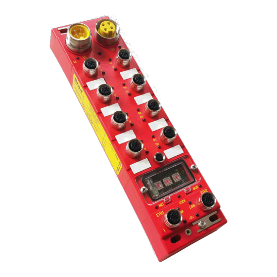
3. Product Overview This chapter gives an overview of the product usage and main features. Introduction EtherNet/IP™ CIP Safety™ Brad™ HarshIO modules provide a reliable solution for the monitoring of safety input devices (interlock switches, emergency stops, light curtains, laser scanners …) as well as the control of safety output devices (relays, muting lamps, fail-safe motor starters…) with industrial safety controllers in harsh duty environments. - Page 17 The combination of EtherNet/IP and CIP Safety protocols allow exchanging safety process I/O and diagnostics information over a single Ethernet network. The modules need to be configured in order to suit with the safety function definitions, up to SIL 3 as defined by IEC 61508 or CAT 4/ PLe as defined by ISO 13849-1 (in particular, inputs and outputs could be set for use as dual-channel).
-
Page 18: Functional Safety - Safety Relevant Parameters
Functional safety - safety relevant parameters This chapter describes parameters associated to functional safety. In according to IEC 61508, Safety means first that a system is free from unwarrantable risks. Functional safety is a part of the total safety, which guarantees the fail-safe response of a safety system according to the input conditions. -
Page 19: Product Environmental And Safety Instructions
Product environmental and safety instructions Approvals, directives, standards The HarshIO safety module has been designed to comply with the following directives and standards: Conformity and approval 2006/42/EC Machinery directive 2011/65/UE RoHS 2 directive 2014/30/EU EMC directive for industrial use (Class-B) UL Listed UL 508 Approval for USA and Canada... - Page 20 Explosive environments Danger! This device is not certified for applications in explosive environments (EX-zone) Power supply and Electrical safety The device is developed for operation on 24 VDC power supplies, which correspond to the PELV-/SELV regulations in accordance to EN 50178. Risk of injury by electric current! There may only devices be connected to the module, which have a safe separation from the mains (such as 120V/230V/600V) power.
-
Page 21: Product Features
Functional earth (for Ethernet connectors) Diagnostic visible LEDs Easy commissioning via Molex Safety Network Configuration Tool (SNCT) On-board memory key (Window or M8 versions) allowing to store module configuration and perform replacement in few minutes without any special tool or re-commissioning. -
Page 22: Ordering Information
4-pin 7/8” power connector versions SAP No Material No Description EtherNet/IP CIP Safety IP67 module, 4-pin power connector, 112095-5107 TCDEC-8B4P-DYU-GW 12 Safety Inputs + 4 Safety Outputs, Windows key EtherNet/IP CIP Safety IP67 module, 4-pin power connector, 112095-5127 TCDEC-8B4P-DYU-G8 12 Safety Inputs + 4 Safety... -
Page 23: Ethernet Topologies
Ethernet topologies EtherNet/IP CIP Safety HarshIO IO module can be used with a protocol compliant scanner as part of control system architecture. The modules built-in 2-port Ethernet DLR capable switch allowing to use the network topology that meets the application needs. These topologies include the following: ... - Page 24 Daisy-chain topology Daisy-chain ring topology is the easiest way to add more EtherNet/IP CIP Safety HarshIO IO module or additional devices in the system by daisy-chaining, or connecting each industrial device in series to the next. This topology is the simplest and cost-effective solution because it takes full advantage of the dual port Ethernet switch integrated in HarshIO modules and reduces the overall Ethernet cable length.
- Page 25 Combination of star and daisy-chain topology Combining star and daisy-chain topology allows connecting EtherNet/IP CIP Safety HarshIO IO modules with mixed HarshIO modules or additional devices. 25 EtherNet/IP™ CIP Safety™ IP67 HarshIO 600 IP67 Safety Digital I/O Modules...
- Page 26 DLR Ring topology DLR ring topology allows including mixed I/O modules and additional devices in a ring. Performing maintenance on one module – for example, by removing the network cable, or by removing a module does not affect other modules as the disruption can be detected and the CIP safety communication can be then routed adequately.
-
Page 27: Functional Safety Functions
4. Functional Safety Functions EtherNet/IP CIP Safety HarshIO modules can achieve the following safety classes by making suitable parameter settings and wiring. Safety Classes I/O Configuration Per IEC 61508 / IEC 62061 Per ISO 13849-1 Dual I/O Channel SIL 3 PL e / Cat. -
Page 28: Safety Inputs
Safety Inputs Safety inputs are used to report the state of safety input devices. A safety input can be configured as: Not Used (default) - the input is disable and doesn’t participate in any safety function Safety - the input participates to the safety function, but does not have a dependency on a test output ... - Page 29 Using a Test Output A test output can be configured as Pulse Test – When the external contact of the safety device is closed, the test output pulse allows diagnosing external wiring faults as stuck with the power supply or short with the other safety input from the same M12 connector.
- Page 30 When test output is activated, Muting Lamp feature controls the output current. Below 5mA, a fault is detected and the status is 0=OFF. Above 25mA is normal operation, the status is 1=ON. Below is a typical scenario for muting lamp broken wire detection: Test Output Process Value Muting Lamp Physical State Muting Lamp Status...
- Page 31 Set Dual-channel Mode and Discrepancy Time To support redundant channel safety devices, the consistency between signals on two input channels can be evaluated. This type of redundant wiring is called dual-channel mode. Note! The dual-channel feature can only work by using the 2 safety input signals of the same M12 port of the HarshIO.
- Page 32 Notes! (1) When dual channel inputs are configured as “Standard” or “Safety”, only internal hardware faults and discrepancy between inputs can be detected. Inputs shall be configured as “Safety Pulse Test” to allow external short to 1 detection At inputs transition, during the discrepancy time, inputs are reported at the safe state Safety Input Fault Recovery...
-
Page 33: Safety Sourcing Outputs (Tcdec-8B4P-D1U-Gx And Tcdec-8B4P-Dyu-Gx)
Safety Sourcing Outputs (TCDEC-8B4P-D1U-Gx and TCDEC-8B4P-DYU-Gx) Safety sourcing outputs are used to drive the state of output devices. Note! HarshIO safe outputs are: current sourcing at max. 1A short circuit protected pulse test configurable A Safety Output can be configured as: ... - Page 34 Notes! Safety Sourcing outputs should not be used to provide power to a device or sub-system whom the resistive and capacitive load could vary during operation. Warning! Be careful of the response time of the output device to prevent any malfunction because of pulse test.
- Page 35 Using Safety Sourcing Outputs in Single-Channel Outputs Outputs from the same M12 connector are configured as 2 single channel outputs. When activated by the logic controller, output is turned ON and status is “1” (good) as long as no fault is detected.
- Page 36 Safety Output Fault Recovery Note! If a fault is detected, the safety output (or safety outputs) physical value remains in the safety state until the following procedure is applied: Removed the cause of the fault. Set the safety output to his safety state. Output Error Latch Time The Output Error Latch Time is a unique parameter that applies for all the Outputs.
-
Page 37: Bipolar Safety Outputs (Tcdec-8B4B-D1U-Gx And Tcdec-8B4B-Dyu-Gx)
Bipolar Safety Outputs (TCDEC-8B4B-D1U-Gx and TCDEC-8B4B-DYU-Gx) Bipolar safety outputs are used to drive the state of output devices. The bipolar outputs combines the safety sourcing output and the safety sinking output of the same M12 connector as a output pair in dual channel mode and can support current up to 2A. Note! HarshIO bipolar safety outputs are: ... - Page 38 Note! A frequent use of bipolar safety outputs is to power and Molex non-safe HarshIO modules from the bipolar M12 connector. A special M12 – Mini change cable can be ordered for easy wiring. In this case: ...
-
Page 39: I/O Status
I/O Status HarshIO safety module provides status information to monitor the I/O circuit. The status information can be read by the EtherNet/IP scanner. Note! When a fault is detected, the status value is “0” meaning bad. On normal operation, the status value is “1”... - Page 40 Overvoltage/under Whole module (all voltage error on input safety inputs and Power cycle needed power (UB) outputs) Whole module (all Overvoltage error on safety inputs and Power cycle needed output power (UL) outputs) 1. Remove the fault Under voltage error on All Safety outputs output power (UL) 2.
-
Page 41: Response Time
Response Time Calculate the response time In order to calculate the response time of a safety function, the worst-case response times of all components involved must be added to the delays on the communication paths. Below are the response times of the HarshIO safety modules to perform these calculations. -
Page 42: Product Characteristics
5. Product Characteristics Hardware characteristics 12x Safe Inputs + Type 12x Safe Inputs + 4x Safe Outputs 2x Bipolar Safe Outputs TCDEC-8B4P-DYU-G TCDEC-8B4B-DYU-G Product Reference TCDEC-8B4P-D1U-G TCDEC-8B4B-D1U-G Safety SIL (per IEC 61508 / IEC 62061) Up to SIL3 (when configured in dual I/O Channel) CAT (per ISO 13849-1) Up to Cat. - Page 43 Pulse Test Output Test rate interval Max. 12ms Pulse test length Sensor power supply 0.7A Max short circuit current 2A at 25° Safe Outputs Output type Sourcing (PNP) Bipolar Channels 4 channels, 2-wires 2 channels, 2-wires Output voltage Connector M12 Ultra-Lock, 5-pin, female, A-Coded, stainless steel Test rate interval Max.
- Page 44 Fieldbus Ethernet connectors M12, 4-pin, female, D-Coded, stainless steel, shielded IP setting DHCP based on MAC (infinite lease), DHCP based on Name, Static IP CIP Safety EtherNet/IP Adapter according specification Vol 5-2.6 (CIP Safety) and Vol 2 – 1.18 Protocol (EtherNet/IP) Data access Implicit messages for I/O data transfer...
- Page 45 Mechanical Housing dimension 235 x 60 x 44 mm (9.25"x2.36x1.73") Housing material PBT VALOX 420 SEO RED 7701 Flammability Standard UL 94 V-0 Corner mounting hole 4 mounting holes, 5 x10 mm Yes, stainless steel (allows the continuity of the ground when the module is mounted on the Ground stud chassis machine) Memory Key...
- Page 46 2kV line to earth on communication ports Warning! Molex devices comply with EU directives and conform (DoC) to the related EMC standards so that they can be easily integrated into other devices or machines. However, EMC compliance of the whole system remains under system builder responsibility.
-
Page 47: Mechanical Characteristics
Mechanical characteristics Size and dimensions (in mm) 47 EtherNet/IP™ CIP Safety™ IP67 HarshIO 600 IP67 Safety Digital I/O Modules... -
Page 48: Physical I/O Mapping
Physical I/O mapping 4-pin power connector 5-pin power connector 48 EtherNet/IP™ CIP Safety™ IP67 HarshIO 600 IP67 Safety Digital I/O Modules... -
Page 49: Safety I/O Assemblies
Safety I/O assemblies The I/O process data are available through the EtherNet/IP assemblies which depend on the required data: Safety Input Process Data Safety Discrete Input Profiles Assembly 524 (20C Hex) Assembly 540 (21C Hex) Assembly 556 (22C Hex) ... -
Page 50: Safety I/O Connections
Safety I/O connections The I/O module supports 1x Exclusive Owner (EO) connection for controlling safe Input/Output process data. 1x Input Only (IO) connection for reading safe Input/Output process data with a safe or non-safe EtherNet/IP scanner. Up to 7 Listen Only (LO) (to read safe process data with a non-safe EtherNet/IP scanner). Exclusive owner This connection is bi-directional: the originator (safety PLC) produces data consumed by the target (HarshIO safety) and the target produces data that is consumed by the originator. - Page 51 Listen Only connection cannot be established until an Input/Output or Input Only connection has been established, and conversely when the last non-Listen-Only connection has been closed or has timed out, the Listen Only connection will automatically close as well. This connection type is the least-frequently used type. Note! Upload EDS file from the safety module to easily configure the connection.
-
Page 52: Safety I/O Data Mapping
Safety I/O data mapping Safe Inputs assemblies Safety Discrete Input Profiles Byte Bit 15 Bit 14 Bit 13 Bit 12 Bit 11 Bit 10 Bit 9 Bit 8 Bit 7 Bit 6 Bit 5 Bit 4 Bit 3 Bit 2 Bit 1 Bit 0 Offset... - Page 53 Byte Bit 15 Bit 14 Bit 13 Bit 12 Bit 11 Bit 10 Bit 9 Bit 8 Bit 7 Bit 6 Bit 5 Bit 4 Bit 3 Bit 2 Bit 1 Bit 0 Offset Input Data (Assembly 579 - 243 Hex), Size: 1 byte(s) Safety Safety Safety...
- Page 54 Vendor Specific Byte Bit 15 Bit 14 Bit 13 Bit 12 Bit 11 Bit 10 Bit 9 Bit 8 Bit 7 Bit 6 Bit 5 Bit 4 Bit 3 Bit 2 Bit 1 Bit 0 Offset Input Data (Assembly 768 - 300 Hex), Size: 13 byte(s) Safety Safety Safety...
- Page 55 Note! Safety inputs configured as “not used” will report a process value of 0 and a safety status of 1. Safety Outputs Safety Discrete Output Profile Byte Bit 15 Bit 14 Bit 13 Bit 12 Bit 11 Bit 10 Bit 9 Bit 8 Bit 7 Bit 6...
- Page 56 Rockwell Safety controllers. Note! The description of the configuration data in the below table are for information purpose only. In fact, the configuration data are managed and sent directly by Molex SNCT software. Vendor Specific...
- Page 57 ON OFF Delay Input Test Source Input Input Mode OFF ON Delay Input Parameters – Input ON OFF Delay Input Test Source Input Input Mode OFF ON Delay Input Parameters – Input ON OFF Delay Input Test Source Input Input Mode OFF ...
- Page 58 Dual Safe Mode Dual Safe Input Mode Dual Safe Discrepancy Operation Input Discrepancy Time Dual Safe Mode Dual Safe Input Mode Dual Safe Discrepancy Operation Input Discrepancy Time Dual Safe Mode Dual Safe Input Mode 11 / Dual Safe Discrepancy Operation Input 11 / Discrepancy Time Major Version: 1...
- Page 59 Input Ix/Ix+1 Dual Safe Mode • 0: Single • 1: Equivalent • 2: Complementary Dual Safe Input Ix / Ix+1 Discrepancy Time (in ms) A value between 10 and 30000; shall be a multiple of 10. 59 EtherNet/IP™ CIP Safety™ IP67 HarshIO 600 IP67 Safety Digital I/O Modules...
-
Page 60: Pin Assignment
Pin assignment 4-pin power supply versions Note! The shell of the 8x M12 I/O connectors is not connected to earth. If required, You should splice the cable at each end for grounding it. 60 EtherNet/IP™ CIP Safety™ IP67 HarshIO 600 IP67 Safety Digital I/O Modules... - Page 61 5-pin power supply versions Note! The shell of the 8x M12 I/O connectors is not connected to earth. If required, You should splice the cable at each end for grounding it. 61 EtherNet/IP™ CIP Safety™ IP67 HarshIO 600 IP67 Safety Digital I/O Modules...
-
Page 62: Led Assignment
LED assignment LED positions Warning: LEDs are NOT reliable indicators and cannot be guaranteed to provide accurate information. They should ONLY be used for general diagnostics during commissioning or troubleshooting. Do not attempt to use LEDs as operational indicators Shield Plate For protective grounding In-coming Bus Power Connector (Ui) Out-coming Bus Power Connector (Uo) - Page 63 LED assignment Module Logic and Input Power Status LED (UB) Description State Module power supply not connected Module power supply is connected and in is the valid range GREEN (24 VDC -20% to +25%) Module power supply is detected but is outside the valid range YELLOW (24 VDC ...
- Page 64 Safe Output status LEDs (Ox) Safety Description State Output Status Good Output is OFF, or module being configured YELLOW Good Output is ON A fault in the output circuit has been detected, or values received from network for Fault the two outputs used as dual output pair are different. A fault in the other output circuit has been detected (whatever the output mode BLINKING Fault...
- Page 65 Network Status LED (NET) Status Description State No Power / The module is not online. No IP Address The module may not be powered, look at Module Status LED (MOD). Online / The module is Online but has no connection in the established state FLASHING Not Connected (IDLE mode).
-
Page 66: Product Installation And Wiring
6. Product installation and wiring This chapter describes wiring possibilities and associated Safety categories. Power supply The HarshIO safety module shall be powered with 2 separate power supplies: 1x 24 VDC for module logic and safety inputs power 1x 24 VDC for safety Outputs auxiliary power Warning! To comply with CE directive, the module shall be powered from a safety extra-low voltage (SELV) or a protected extra-low voltage source. -
Page 67: Ethernet Connection
Ethernet connection Port Identification The HarshIO safety module embeds a dual-port Ethernet switch identified by ETH1 and ETH2. Wiring By default, the HarshIO safety module is delivered to be compliant with ODVA recommendations: The left M12 connector (ETH1) shield is not connected to functional earth. ... - Page 68 This configuration allows the following wiring: ETHERNET SWITCH Chassis Ground Chassis Chassis Chassis Ground Ground Ground Shield plate position 68 EtherNet/IP™ CIP Safety™ IP67 HarshIO 600 IP67 Safety Digital I/O Modules...
- Page 69 An external shield plate is provided to allow the connection between the two Ethernet shield connector, in order to achieve the following wiring: ETHERNET SWITCH Chassis Ground Chassis Chassis Chassis Ground Ground Ground Shield plate position #2 69 EtherNet/IP™...
-
Page 70: Module Grounding
Module grounding Warning! At least one of the earth connections shown on the schematics must be ground connected to ensure the good operation of the module. 70 EtherNet/IP™ CIP Safety™ IP67 HarshIO 600 IP67 Safety Digital I/O Modules... -
Page 71: I/O Wiring
I/O wiring The following table shows different safety I/O wiring with their corresponding safety categories: Safety Input wirings Single Channel Pulse test Safety Device from Test M12 Port Wiring Category Output Push Button TP0 is configured as 24 V power supply with pulse test 24 VDC... - Page 72 Dual Channel Pulse test Safety Device from Test M12 Port Wiring Category Output E-Stop TP0 and TP1 Door are configured Monitor as 24 V power supply with pulse test 24 VDC 24 VDC TP0 is configured as 24 VDC 24 V power supply ...
- Page 73 Safety Device Pulse test M12 Port Wiring Category Light 3 or 4 Curtain depending on light OSSD2 curtain TP0 is configured as 24 V power supply Emitter Receiver OSSD1 24VDC 24VDC 73 EtherNet/IP™ CIP Safety™ IP67 HarshIO 600 IP67 Safety Digital I/O Modules...
- Page 74 Safety Output wiring Single Channel Safety Device Pulse test M12 Port Wiring Category Relay OUT0 and OUT1 are configured as single channel with pulse test 24VDC OUT1 OUT0 74 EtherNet/IP™ CIP Safety™ IP67 HarshIO 600 IP67 Safety Digital I/O Modules...
- Page 75 Dual Channel Safety Device Pulse test M12 Port Wiring Category Relay OUT0 and OUT1 are configured as dual channel with pulse test 24VDC OUT1 OUT0 75 EtherNet/IP™ CIP Safety™ IP67 HarshIO 600 IP67 Safety Digital I/O Modules...
- Page 76 Bipolar Safety Output wiring Safety Device Pulse test M12 Port Wiring Category Relay Sinking OUT1 OUT0 Sourcing Sinking OUT1 OUT0 Sourcing 76 EtherNet/IP™ CIP Safety™ IP67 HarshIO 600 IP67 Safety Digital I/O Modules...
- Page 77 Muting Lamp wiring Pulse test Safety Device from Test M12 Port Wiring Category Output Muting Lamp 24VDC Feature only available when or TO are configured as a muting lamp output Note! A muting lamp is not a safety device. 77 EtherNet/IP™...
-
Page 78: Product Deployment
7. Product Deployment This chapter presents an example of how to proceed with the commissioning of the HarshIO Safety modules based on the Molex SNCT configuration tool and Rockwell Automation RSLogix™ 5000 software version 20. Getting Started Warning! Uncontrolled processes can lead to personal injury and material damages. - Page 79 Warning! Use a plastic screw driver to turn the rotary switches or wear anti-static equipment. 79 EtherNet/IP™ CIP Safety™ IP67 HarshIO 600 IP67 Safety Digital I/O Modules...
- Page 80 Positions and behavior of 3 rotaries x100 Mode Descriptions rotary rotary rotary Overwrite the 4 byte of the IP address stored in Flash Memory. IP Address: 192.168.1.xyz IP mask: 255.255.255.0 Gateway: 192.168.1.1 (except then the IP address is 192.168.1.1 then Gateway address is 0.0.0.0). Note! Addresses (xyz) in the range from 1 to 254 can be allocated.
- Page 81 The module enters in the update FPGA and firmware mode. Update Note! Firmware Please contact Molex technical support for further information. HarshIO module gets its IP address, IP mask address and gateway address according information stored in its Flash memory.
- Page 82 Note! When changing DHCP to Stored mode, all the IP settings are saved in the modules (address, mask, gateway) as it was set during DHCP transaction (given by the DHCP server). Warning! After setting the IP address, the window shall be closed and not open anymore during working operation.
- Page 83 Setting module IP address using EtherNet/IP Explicit Messages 1. Use of Molex EtherNet/IP Tools To change the IP settings of the module, you have to use a software tool like Molex EtherNet/IP Tools that manages Explicit Messaging requests to access module CIP objects...
- Page 84 Select Send List Identity Request on UDP to discover all the EtherNet/IP devices connected to the network. Then select by clicking one EtherNet/IP device in the station list. The device selected should have its IP address set in the Station: <IP> area. Click on 0xF5 TCP/IP tab and then on Get_Attribute_All.
-
Page 85: Eds Files
The EDS files are simple text files used by network configuration tools to help identifying products and easily commission them on a network. For example below a screen shot of Molex EtherNet/IP Scanner Configuration Tool (SNCT Master) showing the commissioning of EtherNet/IP CIP Safety HarshIO module using its EDS file. - Page 86 EDS file list according the associated HarshIO EtherNet/IP CIP Safety module versions: 4-pin 7/8” power connector versions SAP # Material # EDS File Name Product Code 112095-5107 0008002306220100.eds 1570 - 0x622 TCDEC-8B4P-DYU-GW 112095-5127 0008002306220100.eds 1570 - 0x622 TCDEC-8B4P-DYU-G8 112095-5108 00080023062A0100.eds 1578 - 0x62A TCDEC-8B4B-DYU-GW 112095-5128 00080023062A0100.eds...
- Page 87 From Molex web site The EDS files as well as the product documentation can be downloaded from the Molex web site. http://www.molex.com/molex/mysst/DownloadCenter.action and use “Option 1 - Select the Product Lines and/or Search by part number” to look for TCDEC-8xxP-DxU-Gx part number.
- Page 88 Upload EDS from the module The EDS file can also be uploading from the HarshIO modules. A tool like Rockwell RSLinx software can be used to call the Upload EDS from device service. See the next section Import HarshIO Safety EDS into Rockwell hardware description library for further details.
-
Page 89: Import Harshio Safety Eds Into Rockwell Hardware Description Library
Import HarshIO Safety EDS into Rockwell hardware description library To start the commissioning, the first step is to import the HarshIO Safety EDS file into Rockwell hardware library by using Rockwell Automation RSLinx™ software. Start Rockwell RSLinx software. 89 EtherNet/IP™... - Page 90 Select Menu Communications/Configure Drivers… Select EtherNet/IP Driver 90 EtherNet/IP™ CIP Safety™ IP67 HarshIO 600 IP67 Safety Digital I/O Modules...
- Page 91 Set a name for the Driver. If there is multiple network interfaces in the computer, select the correct one to communicate with the HarshIO module. 91 EtherNet/IP™ CIP Safety™ IP67 HarshIO 600 IP67 Safety Digital I/O Modules...
- Page 92 Check that the Driver is running. RSLinx is now browsing the network to detect the EtherNet/IP devices. At this stage, the HarshIO Safety module is detected but appears with an icon representing a question mark because the EDS file is not yet imported.
- Page 93 Select the HarshIO module, right-click on mouse and select Upload EDS file from device A new tool is launch. Select Next button. 93 EtherNet/IP™ CIP Safety™ IP67 HarshIO 600 IP67 Safety Digital I/O Modules...
- Page 94 The EDS Wizard is checking the EDS file revision in the device. The EDS Wizard is checking integrity of the EDS file. 94 EtherNet/IP™ CIP Safety™ IP67 HarshIO 600 IP67 Safety Digital I/O Modules...
- Page 95 The EDS Wizard is checking integrity of the icon file. The EDS Wizard is importing the EDS file and icon in the Rockwell hardware library. 95 EtherNet/IP™ CIP Safety™ IP67 HarshIO 600 IP67 Safety Digital I/O Modules...
- Page 96 The EDS Wizard has successfully imported the files. RSLinx has registered correctly the EDS file and displays now the correct icon of the HarshIO eIP module. 96 EtherNet/IP™ CIP Safety™ IP67 HarshIO 600 IP67 Safety Digital I/O Modules...
-
Page 97: Configure Harshio Safety Module Into Rockwell Rslogix 5000 Project
Configure HarshIO Safety module into Rockwell RSLogix 5000 project Start RSLogix5000 software. Select the Ethernet node of the EtherNet/IP connectivity channel. Right-click on mouse and select New Module… 97 EtherNet/IP™ CIP Safety™ IP67 HarshIO 600 IP67 Safety Digital I/O Modules... - Page 98 Look and select in the Catalog Generic EtherNet/IP Safety Module. Select the module, right-click on mouse and select Create 98 EtherNet/IP™ CIP Safety™ IP67 HarshIO 600 IP67 Safety Digital I/O Modules...
- Page 99 Give a Name and set the module IP address that has been discovered by RSLinx. RSLogix software creates automatically a Safety Network Number (also called SNN). The Safety Network Number is a unique identifier of 48-bit number to prevent the acceptance of connection requests that have been misdirected.
-
Page 100: Safety I/O Assemblies
In the Connection Parameters area, select Change In the Module tab, change the following parameters: Vendor: 8 (Molex) Product Type: 35 Product Code: 1570 Safety I/O assemblies The Input Data and Output Data shall be set to Safety. - Page 101 Change the Connection Assembly settings. In our example, we are going to connect the Safety Input and Safety Outputs Vendor Specific assemblies. Note! The HarshIO module supports different kind of safety I/O connections according the number and type of process data the application needs to access. List of safety I/O connections are available in I/O data mapping.
- Page 102 Disable the Configuration Signature to apply the change. Select Yes to apply the new parameters. 102 EtherNet/IP™ CIP Safety™ IP67 HarshIO 600 IP67 Safety Digital I/O Modules...
-
Page 103: Configure Harshio Safety Module In Molex Snct
Configure HarshIO Safety module in Molex SNCT Molex Safety Network Configuration Tool (SNCT) is free software delivered on the USB stick included in the product package or can be downloaded from the Molex web site. http://www.molex.com/molex/mysst/DownloadCenter.action Warning! To browse and download software from the Molex web site, you must accept the use of cookies in the Internet explorer. - Page 104 Start Molex SNCT software. And select File/New 104 EtherNet/IP™ CIP Safety™ IP67 HarshIO 600 IP67 Safety Digital I/O Modules...
- Page 105 Select the HarshIO Safety module and its version. The next step is to setup the Safety Network Number. 105 EtherNet/IP™ CIP Safety™ IP67 HarshIO 600 IP67 Safety Digital I/O Modules...
- Page 106 From the RSLogix 5000 software, go to HarshIO module properties dialog box. Select the Safety Network Number parameters button. Copy the SNN in the clipboard and paste it in the SNCT software. 106 EtherNet/IP™ CIP Safety™ IP67 HarshIO 600 IP67 Safety Digital I/O Modules...
- Page 107 Connect to the module by choosing Action menu et select Online If the TUNID is different than the one configured in the module, the following message is displayed: If some existing parameters were already set in the module, the following message is displayed: ...
- Page 108 Select Set TUNID in Device button. Note! If you get the below message means that the module has already a TUNID configured. Perform a Safety Reset before to be able to set the TUNID. Go to the Safety Operation tab and select the Safety Reset button. ...
- Page 109 Select Yes to reset the module TUNID and configuration. The module is successfully reset. Note! Be careful then setting TUNID that no EtherNet/IP Scanner I/O connections are open otherwise the setting of TUNID will failed. 109 EtherNet/IP™ CIP Safety™ IP67 HarshIO 600 IP67 Safety Digital I/O Modules...
- Page 110 The setting of TUNID is successful. The next step is to configure the module. Note! Now that the TUNID is configured, it is possible to save the module configuration. Select File / Save. The default file name is the concatenation of the HarshIO product number and TUNID configured in the module.
- Page 111 Select the Module Configuration tab to define the parameters for the Safety Inputs and Safety Outputs. Safety Inputs Configuration 1. Point Operation Type Type Comments Single Safety Inputs are treated separately. Equivalent Safety Inputs are treated as an Equivalent dual-channel. The evaluation is done after discrepancy time.
- Page 112 3. Test Source Select the appropriate Test Source for the Safety Input. Note! The Test source can only be selected when a Point Mode has been set to Safety Pulse Test. Note! The Test Source can only be set to one of the associated M12 connector. 4.
- Page 113 Safety Outputs Configuration 1. Point Operation Type Mode Comments Single The Safety Outputs are treated separately. Dual Channel The Safety Outputs are treated as a dual-channel. 2. Point mode Mode Comments Not used Output is disabled. Safety No Pulse Test Output is enabled and NO pulse test is generated.
- Page 114 When the safety I/O setting is completed, the next step is to download the configuration in the module. Note! If you have defined a password to protect the module configuration, the SNCT will ask to fill the password for the next Safety Operation. Select the Safety Operation tab and click on Download Configuration to Device.
- Page 115 Warning! The validation of the configuration signature is an important step of the module commissioning. It is the role as a Safety Expert to ensure that the configuration file sent to the module is correctly transferred by verifying the signature calculated by both SNCT software and HarshIO module.
- Page 116 Verification of the transferred module configuration The module is configured now. You can verify the configuration signature by clicking the button Read from device to check that both SNCT configuration and Device configuration are identical. Identical signature It is also part of the safety process to control visually the correct match of the Safety Input and Safety Output parameters.
- Page 117 A window shows one-by-one the I/O parameters. Note! It is voluntary that the differences found are not highlighted because the checking has to be done by a Safety Expert body, and not by the SNCT software. Warning! It is part of the safety process to realize a test system of each safe input and safe Output configured.
- Page 118 Lock the configuration to protect it from any user modification. The module is now locked. 118 EtherNet/IP™ CIP Safety™ IP67 HarshIO 600 IP67 Safety Digital I/O Modules...
-
Page 119: Connection And Testing Of Harshio Safety Module In Rslogix 5000
Connection and testing of HarshIO Safety module in RSLogix 5000 Importing the module signature in Logix5000 Go to Safety Operation and select Copy. In RSLogix, open the HarshIO module Properties window and select Safety Tab. 119 EtherNet/IP™ CIP Safety™ IP67 HarshIO 600 IP67 Safety Digital I/O Modules... - Page 120 Click on the Paste button. To finalize the configuration, adjust the RPI for the Safety Input connection at the required Value. Warning! The minimum RPI for the Safety HarshIO is 10ms. Warning! If configuration signature is unchecked, authorized personal needs to ensure that the Controller and HarshIO have the correct configuration.
- Page 121 Go Online and download the controller project. Switch the safety controller in Run mode. The safety module connection is established and running. You can now access to the safety process data and start writing the safety control application. 121 EtherNet/IP™...
-
Page 122: Ethernet/Ip Behavior
8. EtherNet/IP Behavior This chapter gives a presentation of HarshIO safety modules behavior related to EtherNet/IP communication. I/O behavior When the HarshIO module is running (Scanner connection in progress) if the module detects a connection lost with the Scanner, the module sets automatically the safety output process data to “0”. The detection of the connection lost with the Scanner is calculated based on the time-out (multiplier x RPI) defined in the I/O connection (Safety_Forward_Open request) sent by the Scanner. -
Page 123: Ethernet/Ip Object Classes
EtherNet/IP Object Classes Identity (0x01) This object allows reading the identity of the module. Class Attributes Description Limits 1 Revision 1 Max Instance 1 Number of instances Supported Not supported Class Services Service Param. - Page 124 Message Router (0x02) Class Attributes Description Limits Revision Optional Attribute List Optional Service List Max ID of class attributes Max ID of instance attributes Supported Not Supported Class Services Service Param.
- Page 125 Assembly (0x04) This object allows to access I/O process data. Class Attributes Description Limits 2 Revision 199 Max Instance 4 Number of instances Supported Not supported Class Services Service Param. Options Get_Attribute_Single ...
- Page 126 Connection Manager (0x06) Class Attributes Description Limits 1 Revision 1 Max Instance 1 Number of instances Supported Not supported Class Services Service Param. Options Get_Attributes_All Get_Attribute_Single Instance Attributes Description Limits Open Requests ...
- Page 127 TCP/IP Interface (0xF5) Class Attributes Description Limits 2 Revision 1 Max Instance 1 Number of instances Supported Not supported Class Services Service Param. Options Get_Attributes_All Get_Attribute_Single Instance Attributes Description Limits Status ...
- Page 128 Ethernet Link (0xF6) Class Attributes Description Limits 3 Revision 3 Max Instance 3 Number of Instance Supported Not supported Class Services Service Param. Options Get_Attributes_All Get_Attribute_Single Instance Attributes Description Limits Interface Speed ...
- Page 129 DLR (0x47) Class Attributes Description Limits 3 Revision 1 Max Instance Supported Not supported Class Services Service Param. Options Get_Attribute_Single Instance Attributes Description Limits 0 indicates “Linear” Network Topology 1 indicates “Ring” ...
- Page 130 QoS (0x48) Class Attributes Description Limits 1 Revision 1 Max Instance 1 Number of Instance Supported Not supported Class Services Service Param. Options Get_Attributes_All Get_Attribute_Single Instance Attributes Description Limits DSCP Urgent ...
-
Page 131: Product Replacement
9. Product Replacement This chapter presents the strategy in case of replacement of commissioned HarshIO Safety modules. Before to start This chapter explains how to replace a defective product in an existing application without having to redo the commissioning of a new module and by using the memory key of the faulty module. Note! If the new module does not plan to use the memory key of the defective module. -
Page 132: Replacement Procedure
Replacement procedure Follow these steps in order to perform a successful replacement of a module: 1. Disconnect the 7/8'' power supply cordsets. Danger! Risk of death by electric current! After disconnecting the device from main voltage, parts such as power connections should only be touched when the capacitors are discharged in the device. -
Page 133: Verification
Test the communication with the module using a network tool: i. Sending a PING command from a DOS window ii. Use Molex EIP_Tools software (available on the USB stick delivered with the unit or available free-of-charge here) to detect the module. -
Page 134: Snct Configuration Software
This chapter presents the important features that are available in the SNCT configuration software used for the HarshIO module commissioning. Overview Molex Safety Network Configuration Tool (also called SNCT) is a Windows software tool used to do the safety configuration and commissioning of the HarshIO Safety module. Warning! Molex SNCT is a T3 software tool according to the definition provided by the IEC61508. - Page 135 Most of the features are performed when the SNCT software is connected to the HarshIO module. To go Online/Offline, select the Action menu or click on the following icon: 135 EtherNet/IP™ CIP Safety™ IP67 HarshIO 600 IP67 Safety Digital I/O Modules...
-
Page 136: Safety Reset
Safety Reset The Safety Reset is a command to reset the ownership between the EtherNet/IP Scanner and a HarshIO module in case of one of the below parameter has changed: • HarshIO TCP/IP address • HarshIO Safety Network Number (SNN) •... - Page 137 Select the network interface Perform a module discovery Double click on the module to select it. 137 EtherNet/IP™ CIP Safety™ IP67 HarshIO 600 IP67 Safety Digital I/O Modules...
- Page 138 10. Go Online to connect the module (Action/Online) 11. The SNCT detects a mismatch between the current TUNID set in the project (IP / SNN) and the TUNID stored in the physical module. 12. Select Yes and then OK. 138 EtherNet/IP™...
- Page 139 13. Go to the Safety Operation tab 14. Select Safety Reset button 15. A notification box informs that all permanent information will be reset in the module (SNN, IP address, signature). Select Yes. 16. A notification box informs that the TUNID difference between the configured one in the project and the one in the physical module.
- Page 140 17. At this step, the SNCT is performing verification to know if: a. The module is locked b. The module has no password protection 18. If the module is locked, click on Unlock Device button 19. If the module is protected by a password, enter it and select OK. If the password is unknown, go to the section Reset Password 20.
- Page 141 Select Yes. Select Yes 141 EtherNet/IP™ CIP Safety™ IP67 HarshIO 600 IP67 Safety Digital I/O Modules...
-
Page 142: Lock / Unlock Configuration
Lock / Unlock Configuration The Lock is a feature protecting a HarshIO module to have its configuration modified after a commissioning by a Safety Expert body. Note! If the module is protected by Password, Lock and Unlock actions will require entering the password. - Page 143 Select the network interface Perform a module discovery Double click on the module to select it. 143 EtherNet/IP™ CIP Safety™ IP67 HarshIO 600 IP67 Safety Digital I/O Modules...
- Page 144 Go Online to connect the module (Action/Online) Go to the Safety Operation tab and Select Lock Device button 144 EtherNet/IP™ CIP Safety™ IP67 HarshIO 600 IP67 Safety Digital I/O Modules...
- Page 145 If the module is protected by a password, enter it and select OK. If the password is unknown, go to the section Reset Password The Lock service is successful. 10. To verify the Lock state of the module, a. the Lock LED shall be solid Yellow. ...
- Page 146 b. Go to Module Information tab and click Refresh button to display the Lock State value 11. Go Offline and Exit SNCT 146 EtherNet/IP™ CIP Safety™ IP67 HarshIO 600 IP67 Safety Digital I/O Modules...
- Page 147 Unlock a module configuration The steps to Unlock a module configuration are similar to the Lock procedure steps from 1 to 6. Go to the Safety Operation tab and Select Unlock Device button If the module is protected by a password, enter it and select OK. If the password is unknown, go to the section Reset Password The Unlock service is successful.
- Page 148 10. To verify the Lock state of the module, a. the Lock LED shall be blinking Yellow. b. Go to Module Information tab and click Refresh button 11. Go Offline and Exit SNCT 148 EtherNet/IP™ CIP Safety™ IP67 HarshIO 600 IP67 Safety Digital I/O Modules...
-
Page 149: Stored Ip Address Using Dhcp Server
Stored IP Address using DHCP Server To store an IP address to an out-of-box module follows the procedure: 1. Launch the Molex DHCP Server application (delivered on the USB stick with the product) 149 EtherNet/IP™ CIP Safety™ IP67 HarshIO 600... - Page 150 If it is the first launch of the tool, open the server configuration box (Option / Server Configuration). Select the Ethernet interface card and set the subnet mask. Click OK to close the box. Double click on the line corresponding to the HarshIO to configure. Set the IP address and click OK.
- Page 151 A new entry will be created. Check the Loop check box and the DHCP server starts to send Ping request in cyclically to the module. Now start the SNCT tool. Create or open a project. Select the network interface. Enter IP address of the module or perform a module discovery and select the module.
- Page 152 Go to Module Information tab and click on Refresh. Verify that the module is in “Waiting for TUNID” (if the module is really in out of box state that will be the case). If it not the cases you will not be allow to change IP of the module, so you will need to do a safety reset and restart the procedure at the step #1.
- Page 153 10. In Configuration Control, click on the Change Button 11. In the box, select Static and click Ok. 12. Modification is applied immediately and a message “Modification done with success” is displayed. 13. Click Ok 153 EtherNet/IP™ CIP Safety™ IP67 HarshIO 600 IP67 Safety Digital I/O Modules...
- Page 154 14. In Interface Configuration, click on the Change Button. 15. Provide the new IP address and network mask. 16. Modifications will be immediately applied. 17. SNCT will go Offline and then go Online automatically with the new IP address. Note! Due to the new IP address, a warning could be displayed indicating that configuration parameters are different between configuration and module.
-
Page 155: Ip Address Conflict
IP Address Conflict In case of IP conflict between the HarshIO module and other TCP/IP devices on the network, the module will be able to detect this issue (if ACD feature is enabled). The module will stop by itself to communicate on the network after detecting the problem. -
Page 156: Ethernet Port Diagnostics
Ethernet Port Diagnostics SNCT can provide diagnostic counter on each Ethernet port to monitor the traffic. To get Ethernet port diagnostic follows the below procedure: 1. Start SNCT and Go online (Action/Go Online). 2. Go in IP/Port Configuration page, click on the Refresh Button. 3. -
Page 157: Module Information
Module Information The module information feature allows getting data on the HarshIO module to monitor its current state. To perform a module information follows the below procedure: Note! The procedure is based on the assumption that the module is in an unknown state but has a known IP address. - Page 158 Not Recoverable Fault: A hardware major problem has been detected. You should not use any more the module, contact Molex technical support team. State: This value helps to known the state of the module and define the operations to do: Waiting for TUNID: No TUNID is set in the module;...
-
Page 159: Set/Reset Password
Warning! Be sure to do not lose the password. Even SNCT provides a feature to Reset the password, this procedure takes time due the obligation to the contact to the Molex technical support. To perform a “Set Password”, follow the procedure: 1. - Page 160 In the body, copy and paste the Environment Code (in this example “A8069-2F002”) 9. Molex Technical Support team will manage the request within the business open hours (8:30AM - 18:30PM GMT). A Reset Code will be provided in around 24h after reception of the request.
- Page 161 10. At reception of the answers redo operation 1 to 7 and then replace the ### in the Enter Reset Code fields by the received value: 11. Click OK. 12. If the Reset Password is successful, a message will display “The password has been correctly removed.
-
Page 162: Additional Information
Additional Information The module additional information allows getting advanced information of the module. To get additional information, follows the below procedure: 1. Launch the SNCT 2. Create a new project of the same model of the module 3. Select the network interface 4. - Page 163 Version: This section gives all the versions of the different firmware and hardware components. LED Status: Reflect the current state of the LEDs. Rotary State: Reflect the current positions of the 3 rotaries. Log: This area contains the log messages stored in the module memory. The first message is the most recent one.
-
Page 164: Download Firmware
Download Firmware The feature allows updating the HarshIO firmware. Note! This procedure doesn’t delete the configuration parameters stored in the HarshIO module. Warning! It is highly recommended to use a point-to-point Ethernet connection to transfer the firmware, between the computer and the HarshIO module, to avoid disturbance during the file transfer. - Page 165 Select in the Action menu, Additional Tools/Download Firmware… Browse the computer to locate the HarshIO firmware, select it and click Open. SNCT checks the firmware CRC file and display version information. Click the Transfer button 165 EtherNet/IP™ CIP Safety™ IP67 HarshIO 600 IP67 Safety Digital I/O Modules...
- Page 166 166 EtherNet/IP™ CIP Safety™ IP67 HarshIO 600 IP67 Safety Digital I/O Modules...
- Page 167 Follow the instructions 10. SNCT starts the download and display information during the transfer that takes approximately 30 sec. 167 EtherNet/IP™ CIP Safety™ IP67 HarshIO 600 IP67 Safety Digital I/O Modules...
- Page 168 11. Transfer is done successfully. Follow the instructions to restart the module. 168 EtherNet/IP™ CIP Safety™ IP67 HarshIO 600 IP67 Safety Digital I/O Modules...
-
Page 169: Print Module Configuration
“Safety Inputs”, “Safety Input X and Safety Input Y”, “Safety Outputs”, “Safety Output X and Safety Output Y” have the same values. If the configuration signatures are equal but the verification shows differences contact Molex technical support team. Follow the below steps to generate a listing:... - Page 170 4. Generate the listing (File/Print) 5. Ensure that is the correct module by verifying in the listing the IP and SNN. 6. Compare the signatures (In SNCT / In Module) in the listing. 170 EtherNet/IP™ CIP Safety™ IP67 HarshIO 600 IP67 Safety Digital I/O Modules...
- Page 171 7. Compare each parameters in the section “Safety Inputs”, “Safety Input X and Safety Input Y”, “Safety Outputs”, “Safety Output X and Safety Output Y” Note! Values rounded below are value set in the configuration assembly and are described in the section “Safety I/O data mapping / Configuration Data”.
-
Page 172: Log (Emergency Mode)
This is an expert feature to retrieve the log information of the module that is not operating anymore. Note! This feature must be used only on request of the Molex technical support team. 172 EtherNet/IP™ CIP Safety™ IP67 HarshIO 600... -
Page 173: Product Package
Software Network Configuration Tool (also called SNCT) HarshIO module description files (EDS) Technical Notes Unsupported network software tools developed by Molex to help the product commissioning A DHCP/BOOTP Server A diagnostic EtherNet/IP tools - EIP_Tools CAD files ... -
Page 174: Memory Key
Memory Key Depending on the module version, a memory key is delivered in 2 versions: M8 key or Window key. M8 Memory Key Window Memory Key Size: 36 x 11 x 11 mm Size: 18 x 6 x 7 mm The key stores all information including module parameters and "safe"... - Page 175 Note! The HarshIO safety module can operate only if a single key is inserted. If a second key is detected, the module is directly switching in fail safe mode and all the I/O leds will blink in red color. 175 EtherNet/IP™...
-
Page 176: Web Server Interface
12. Web Server Interface This chapter presents the HarshIO information available by connecting the module web server. How to connect the web server The web server interface offers the user a convenient and simple method for the diagnosis of HarshIO module thru a web browser (Internet Explorer, Firefox, etc…). -
Page 177: General Information
General information This page shows the information of the HarshIO safety module. 177 EtherNet/IP™ CIP Safety™ IP67 HarshIO 600 IP67 Safety Digital I/O Modules... -
Page 178: Diagnostic Information
Diagnostic information This page shows the network interface diagnostic information. 178 EtherNet/IP™ CIP Safety™ IP67 HarshIO 600 IP67 Safety Digital I/O Modules... - Page 179 This page shows the Ethernet and EtherNet/IP diagnostic information. 179 EtherNet/IP™ CIP Safety™ IP67 HarshIO 600 IP67 Safety Digital I/O Modules...
-
Page 180: Selection Of Cables And Cordsets
This chapter presents how to access to a selection of connectivity products and associated part numbers to help designing the system infrastructure. Overview Molex connectivity product portfolio includes a full range of cables, cordsets and connectors to perform reliable wiring of the installation in harsh environments. Please visit Molex web site to browse and discover the solutions. -
Page 181: Certifications
14. Certifications 181 EtherNet/IP™ CIP Safety™ IP67 HarshIO 600 IP67 Safety Digital I/O Modules... -
Page 182: Tuv Certificate
TUV Certificate 182 EtherNet/IP™ CIP Safety™ IP67 HarshIO 600 IP67 Safety Digital I/O Modules... -
Page 183: Eu Declarations Of Conformity
EU Declarations of Conformity EU Declaration of Conformity (DoC) Company Name: Molex Ireland Ltd. Postal address: Shannon Industrial Estate Postcode and city: Co. Clare, Shannon Telephone number: +353 61 702 400 E-Mail address: ic.support.eu@molex.com Declare that the DoC is issued under our sole responsibility and belongs to the following products... - Page 184 EU Declaration of Conformity (DoC) Company Name: Molex Ireland Ltd. Postal address: Shannon Industrial Estate Postcode and city: Co. Clare, Shannon Telephone number: +353 61 702 400 E-Mail address: ic.support.eu@molex.com Declare that the DoC is issued under our sole responsibility and belongs to the following products...
-
Page 185: Product Support
15. Product Support Warranty conditions The warranty conditions may be found in the "General terms and conditions" on the Molex web site: (www.molex.com). Product Information Please ensure that the following information is available before calling for technical support: Module type and serial number ... -
Page 186: Technical Support
Technical Support To assist users in using the products, Molex provides technical information on its web site: Molex Support and Download They can find particularly: Downloads center Support Request Form Knowledge Base Worldwide technical support contacts ... - Page 187 Brad™ from Molex Zone d’Activité du Thuit Anger 185 H Voie Romaine 27370 LE THUIT ANGER – FRANCE 187 EtherNet/IP™ CIP Safety™ IP67 HarshIO 600 IP67 Safety Digital I/O Modules...
Need help?
Do you have a question about the TCDEC-8B4P-DYU-GW and is the answer not in the manual?
Questions and answers