Table of Contents
Advertisement
SERVICE MANUAL
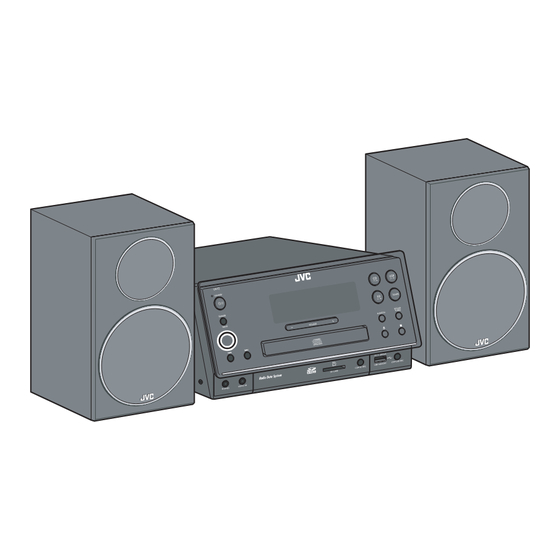
MICRO COMPONENT SYSTEM
6 S ERVICE MANUAL
MB736<Rev.003>
2010
UX-F2BE, UX-F2BEN, UX-F2BEV,
UX-F2BUS, UX-F2BUW
COPYRIGHT © 2010 Victor Company of Japan, Limited
Lead free solder used in the board (material : Sn-Ag-Cu, melting point : 219 Centigrade)
1
PRECAUTION. . . . . . . . . . . . . . . . . . . . . . . . . . . . . . . . . . . . . . . . . . . . . . . . . . . . . . . . . . . . . . . . . . . . . . . . . 1-4
2
SPECIFIC SERVICE INSTRUCTIONS . . . . . . . . . . . . . . . . . . . . . . . . . . . . . . . . . . . . . . . . . . . . . . . . . . . . . . 1-7
3
DISASSEMBLY . . . . . . . . . . . . . . . . . . . . . . . . . . . . . . . . . . . . . . . . . . . . . . . . . . . . . . . . . . . . . . . . . . . . . . . 1-7
4
ADJUSTMENT . . . . . . . . . . . . . . . . . . . . . . . . . . . . . . . . . . . . . . . . . . . . . . . . . . . . . . . . . . . . . . . . . . . . . . . 1-10
5
TROUBLESHOOTING . . . . . . . . . . . . . . . . . . . . . . . . . . . . . . . . . . . . . . . . . . . . . . . . . . . . . . . . . . . . . . . . . 1-10
TABLE OF CONTENTS
COPYRIGHT © 2010 Victor Company of Japan, Limited
only for Europe
No.MB736<Rev.003>
2010/6
Advertisement
Chapters
Table of Contents

Related Manuals for JVC UX-F2BEN


Summary of Contents for JVC UX-F2BEN
-
Page 1: Table Of Contents
MICRO COMPONENT SYSTEM MB736<Rev.003> 2010 6 S ERVICE MANUAL UX-F2BE, UX-F2BEN, UX-F2BEV, UX-F2BUS, UX-F2BUW only for Europe COPYRIGHT © 2010 Victor Company of Japan, Limited Lead free solder used in the board (material : Sn-Ag-Cu, melting point : 219 Centigrade) TABLE OF CONTENTS PRECAUTION. - Page 2 SPECIFICATION For Europe(Main unit CA-UXF2B) General Power source AC 230 V , 50 Hz Power consumption (at operation) 40 W Power consumption (on standby) 1.00 W or less Dimensions (approx.) (W x H x D) (including projecting parts) 236 mm × 123 mm × 285 mm Mass (approx.) 2.0 kg Amplifier...
- Page 3 SPECIFICATION For Asia(Main unit CA-UXF2B) General Power source AC 110 - 127 V/AC 220 - 240 V (adjustable with the voltage selector), 50 Hz/60 Hz Power consumption (at operation) 40 W Power consumption (on standby) 1.00 W or less Dimensions (approx.) (W x H x D) (including projecting parts) 236 mm × 123 mm × 285 mm Mass (approx.) 2.0 kg Amplifier...
-
Page 4: Precaution
SECTION 1 PRECAUTION Safety Precautions (1) This design of this product contains special hardware and voltmeter. many circuits and components specially for safety purpos- Move the resistor connection to each exposed metal es. For continued protection, no changes should be made part, particularly any exposed metal part having a return to the original design unless authorized in writing by the path to the chassis, and measure the AC voltage across... - Page 5 Preventing static electricity Electrostatic discharge (ESD), which occurs when static electricity stored in the body, fabric, etc. is discharged, can destroy the laser diode in the traverse unit (optical pickup). Take care to prevent this when performing repairs. 1.5.1 Grounding to prevent damage by static electricity Static electricity in the work area can destroy the optical pickup (laser diode) in devices such as laser products.
- Page 6 Important for laser products 1.CLASS 1 LASER PRODUCT 5.CAUTION : If safety switches malfunction, the laser is able to function. 2.CAUTION : (For U.S.A.) Visible and/or invisible class II laser radiation 6.CAUTION : Use of controls, adjustments or performance of when open.
-
Page 7: Specific Service Instructions
SECTION 2 SPECIFIC SERVICE INSTRUCTIONS This service manual does not describe SPECIFIC SERVICE INSTRUCTIONS. SECTION 3 DISASSEMBLY Main body (Used model: UX-F2E) 3.1.1 Removing the Top cover (See Fig.1, 2, 3) 3.1.2 Removing the Main board (See Fig.4) (1) Remove the four screws A attaching the Top cover. (See (1) Disconnect the connector wire from Jack board connected Fig.1) to connector... - Page 8 3.1.3 Removing the SMPS board (See Fig.5, 6) (2) Remove the two screws M and two screws N attaching the (1) Disconnect the connector wire from Display board connect- CD mechanism. (See Fig.8) ed to connector CN902 of the SMPS board. (See Fig.5) CN902 Fig.5 (2) Remove the two screws G, one screw H and one screw J...
- Page 9 3.1.5 Removing the MPEG board (See Fig.12) 3.1.7 Removing the Jack board (See Fig.15) (1) Disconnect the card wire from USB board connected to (1) Remove the two screws Q attaching the Jack board. connector CN108 of the MPEG board. (2) Remove the four screws P attaching the MPEG board.
-
Page 10: Adjustment
SECTION 4 ADJUSTMENT This service manual does not describe ADJUSTMENT. SECTION 5 TROUBLESHOOTING This service manual does not describe TROUBLESHOOTING. 1-10 (No.MB736<Rev.003>) - Page 11 (No.MB736<Rev.003>)1-11...
- Page 12 Victor Company of Japan, Limited Home Entertainment Business Division Personal AV Operation 10-1,1chome,Ohwatari-machi,Maebashi-city,371-8543,Japan (No.MB736<Rev.003>) Printed in Japan...
- Page 13 REVISION INFORMATION MICRO COMPONENT SYSTEM UX-F2BE, UX-F2BEN, UX-F2BEV ■ OVERVIEW Add UX-F2BEV. ■ DETAILS COVER SECTION Title Line No.MB736<Rev.001> No.MB736<Rev.002> Description Revision Rev.001 Rev.002 Model No. UX-F2BE, UX-F2BEN UX-F2BE, UX-F2BEN, UX-F2BEV SECTION 1 PRECAUTION Title Line No.MB736<Rev.001> No.MB736<Rev.002> Description 1.1 Safety 3 3.
- Page 14 PARTS LIST MODEL No. LIST Model No. No.MB736<Rev.002> UX-F2BE UX-F2BEN UX-F2BEV General assembly [M1MM] Part No. Symbol Part Name Description Models <Rev.001> <Rev.002> M1MM ------------ CD7111091800300 RATING LABEL (Addition) 1 03 Packing and accessories [M3MM] Part No. Symbol Part Name...
- Page 15 (MB736-R002) 3...
- Page 16 Victor Company of Japan, Limited Home Entertainment Business Division Personal AV Operation 10-1,1chome,Ohwatari-machi,Maebashi-city,371-8543,Japan (MB736-R002) Printed in Japan No.MB736<Rev.001>...
-
Page 17: Ux-F2Be, Ux-F2Ben, Ux-F2Bev, Ux-F2Bus, Ux-F2Buw
REVISION INFORMATION MICRO COMPONENT SYSTEM UX-F2BE, UX-F2BEN, UX-F2BEV, UX-F2BUS, UX-F2BUW ■ OVERVIEW Add UX-F2BUS and UX-F2BUW. ■ DETAILS COVER SECTION Title Line No.MB736<Rev.002> No.MB736<Rev.003> Description Revision Rev.002 Rev.003 Issue Date 2010/04 2010/06 Model No. UX-F2BE, UX-F2BEN, UX-F2BEV UX-F2BE, UX-F2BEN, UX-F2BEV,... - Page 18 Title Line No.MB736<Rev.002> No.MB736<Rev.003> Description 10 - Output Power 100 W (50 W + 50 W) at 6 Ω (10% THD) 11 - Audio Input AUDIO IN: Stereo mini (Φ 3.5 mm) 12 - Speaker impedance 6 Ω - 16 Ω 13 - Tuner 14 -...
- Page 19 PARTS LIST MODEL No. LIST Model No. No.MB736<Rev.003> UX-F2BE UX-F2BEN UX-F2BEV UX-F2BUS UX-F2BUW General assembly [M1MM] Part No. Symbol Part Name Description Models <Rev.002> <Rev.003> M1MM ------------ CD6033226080110 SCREW (Addition) 2 04,05 M1MM ------------ CD5001091800200 FRONT CABINET (Addition) 1 04,05...
- Page 20 Part No. Symbol Part Name Description Models <Rev.002> <Rev.003> 01 C770 ------------ CD1121102082021 C CAPACITOR (Addition) 1 04,05 01 C780 ------------ CD1129226044120 C CAPACITOR (Addition) 1 04,05 01 C781 ------------ CD1129226044120 C CAPACITOR (Addition) 1 04,05 01 C796 ------------ CD1221000042050 C RESISTOR (Addition) 1 04,05 01 C797...
- Page 21 USB board [05] Part No. Symbol Part Name Description Models <Rev.002> <Rev.003> 05 C201 ------------ CD1121104084021 C CAPACITOR (Addition) 1 04,05 05 C202 ------------ CD1138474091210 M CAPACITOR (Addition) 1 04,05 05 C205 ------------ CD1121104084021 C CAPACITOR (Addition) 1 04,05 05 RS3 ------------ CD1121080088020 C CAPACITOR (Addition)
- Page 22 Victor Company of Japan, Limited Home Entertainment Business Division Personal AV Operation 10-1,1chome,Ohwatari-machi,Maebashi-city,371-8543,Japan (MB736-R003) Printed in Japan No.MB736<Rev.002>...
- Page 23 PARTS LIST UX-F2BE,UX-F2BEN,UX-F2BEV,UX-F2BUS,UX-F2BUW MODEL MARK UX-F2BE UX-F2BEN UX-F2BEV UX-F2BUS UX-F2BUW * All printed circuit boards and its assemblies are not available as service parts. - Contents - 3- 2 Exploded view of general assembly and parts list (Block No.M1) 3- 6 Electrical parts list (Block No.01~05)
- Page 24 Exploded view of general assembly and parts list Block No. UX-F2BUS,UW Display board Jack board USB board...
- Page 25 Main board MPEG board 41 81 SMPS board Upgrade board The parts without symbol number are not service.
- Page 26 General Assembly Block No. [M][1][M][M] Symbol No. Part No. Part Name Description Local CD5501091800100 DISPLAY LENS 5501-091800100 CD7902091800101 DOUBLE SIDE PAPER 7902-091800101 CD6033226080110 SCREW 6033-226080110 A,B,C CD6033226080110 SCREW 6033-226080110(x2) CD6306091800100 BRACKET 6306-091800100(x2) CD6211091800100 PANEL FIXING PLATE 6211-091800100(x2) CD5001091800100 FRONT CABINET 5001-091800100 A,B,C CD5001091800200...
- Page 27 Symbol No. Part No. Part Name Description Local CD3002140160900 FFC CABLE 3002-140160900 A,B,C CD3002140160910 FFC CABLE 3002-140160910 CD3002160100910 FFC CABLE 3002-160100910 CD3502060152040 HOUSING 3502-060152040 CD4401120001120 CD MECHANISM 4401-120001120 CD3505080182010 HOUSING 3505-080182010 CD3505070152010 HOUSING 3505-070152010 CD3505060222500 HOUSING 3505-060222500 CD5939080700100 PLASTIC WASHER 5939-080700100 CD8024000004600 FIBER WASHER...
- Page 28 Electrical parts list Main board Symbol No. Part No. Part Name Description Local Block No. [0][1] C645 CD1121101081020 C CAPACITOR 1121-101081020 Symbol No. Part No. Part Name Description Local C646 CD1121101081020 C CAPACITOR 1121-101081020 C647 CD1121101081020 C CAPACITOR 1121-101081020 C648 CD1121101081020...
- Page 29 Symbol No. Part No. Part Name Description Local Symbol No. Part No. Part Name Description Local C764 CD1121102082020 C CAPACITOR 1121-102082020 A,B,C R647 CD1221472052020 C RESISTOR 1221-472052020 C764 CD1121102082021 C CAPACITOR 1121-102082021 R648 CD1221103052020 C RESISTOR 1221-103052020 C765 CD1121102082020 C CAPACITOR 1121-102082020...
- Page 30 Symbol No. Part No. Part Name Description Local Symbol No. Part No. Part Name Description Local R759 CD1221682052020 C RESISTOR 1221-682052020 EC703 CD1132227053064 E CAPACITOR 1132-227053064 R760 CD1221183052020 C RESISTOR 1221-183052020 EC704 CD1132226053060 E CAPACITOR 1132-226053060 R761 CD1221183052020 C RESISTOR 1221-183052020 EC709...
- Page 31 Symbol No. Part No. Part Name Description Local Symbol No. Part No. Part Name Description Local CD1121103082020 C CAPACITOR 1121-103082020 C180 CD1121104082020 C CAPACITOR 1121-104082020 CD1121222082020 C CAPACITOR 1121-222082020 C181 CD1121103082020 C CAPACITOR 1121-103082020 CD1121222082020 C CAPACITOR 1121-222082020 C182 CD1121103082020 C CAPACITOR...
- Page 32 Symbol No. Part No. Part Name Description Local Symbol No. Part No. Part Name Description Local L101 CD2721272030010 FERRITE BEAD 2721-272030010 C506 CD1121104082020 C CAPACITOR 1121-104082020 L102 CD1606010040000 INDUCTOR 1606-010040000 C507 CD1132227053060 E CAPACITOR 1132-227053060 A,B,C C507 CD1132227053064 E CAPACITOR 1132-227053064 CN101...
- Page 33 Symbol No. Part No. Part Name Description Local Symbol No. Part No. Part Name Description Local FB301 CD1221000052020 C RESISTOR 1221-000052020 D912 CD1312158220010 BARRIER DIODE 1312-158220010 FB302 CD1221000052020 C RESISTOR 1221-000052020 D913 CD1312021000000 SCHOTTKY 1312-021000000 BARRIER DIODE FB303 CD2721272020000 FERRITE BEADS 2721-272020000...
- Page 34 Symbol No. Part No. Part Name Description Local Symbol No. Part No. Part Name Description Local R928 CD1221362041030 C RESISTOR 1221-362041030 CN203 CD3101200221010 HEADER 3101-200221010 R929 CD1221000042030 C RESISTOR 1221-000042030 F201 CD1214033000001 THERMISTOR 1214-033000001 R930 CD1221332042030 C RESISTOR 1221-332042030 FB201 CD2721272020000...
- Page 35 Packing materials and accessories parts list Block No. No additional / supplemental order of WARRANTY CARDs are available. US,UW A1,A2,A3,A4 A5,A6,A7 E,EN,EV The parts without symbol number are not service. 3-13...
- Page 36 Packing and Accessories Block No. [M][3][M][M] Symbol No. Part No. Part Name Description Local CD7202091800100 INST BOOK 7202-091800100 GER CD7202091800700 INST BOOK 7202-091800700 SPA CD7202091801200 INST BOOK 7202-091801200 RUS CD7202091800500 INST BOOK 7202-091800500 ENG CD7202091800200 INST BOOK 7202-091800200 FRE CD7202091800800 INST BOOK 7202-091800800 POR...
- Page 37 SCHEMATIC DIAGRAMS MICRO COMPONENT SYSTEM UX-F2BE, UX-F2BEN, UX-F2BEV, UX-F2BUS, UX-F2BUW only for Europe Lead free solder used in the board (material : Sn-Ag-Cu, melting point : 219 Centigrade) Contents Block diagrams Standard schematic diagrams Printed circuit boards 2-11 to 13 No.MB736SCH<Rev.003>...
- Page 38 In regard with component parts appearing on the silk-screen printed side (parts side) of the PWB diagrams, the parts that are printed over with black such as the resistor ( ), diode ( ) and ICP ( ) or identified by the " " mark nearby are critical for safety.
-
Page 39: Block Diagram
Block diagram System control & Audio Amp section X602 X601 U602 QF01 QF03 Q702 ,Q703 32.768K 8MHz CN610 EEPROM A+12V Sensor STBY/MUTE SWITCH CN612 DC Fan UART U604 CD_ON CD traverse U608 X101 IC104 E,VOLUME mechanism MOTOR 27MHz POWER AMP OPEN Speaker DRIVER... -
Page 40: Standard Schematic Diagrams
Standard schematic diagrams <SMPS section 1> J901 L905 L907 R909 C912 C905 C907 L906 D901 J910 RV901 PVCC D905 SW901 RV902 C906 D902 Q901 C935 PRM-GND U901 To SMPS section 2 PRM-GND R944 VCC-H R905 C936 C903 SEC-GND D904 U902-A C917 R903 R904... - Page 41 <SMPS section 2> D917 CN902 J903 C931 -27V FL - Q905 D918 D916 SEC-GND CN903 R923 U904 L911 SEC-GND SEC-GND J907 +12V D913 PVCC R941 SEC-GND C920 L904 D911 U905-B CN904 PRM-GND D919 D912 VCC-L D908 R940 C929 SEC-GND D909 Q903 D915 Q908...
- Page 42 <AMP section> R710 R709 RF01 To MICOM section R711 C709 QF01 DF01 Q706 M+12V A+12V R705 CF03 RF02 AM_HOP CN612 C721 CF05 MGND C723 MGND C715 R728 RF03 PRE_L C708 C710 C716 R727 PRE_R C722 C713 DF02 RF08 RF11 R714 R712 R730 R729...
- Page 43 <MICOM section> A+12V TU+12V +5V_TUNER Q606 Q607 L603 +5V_TUNER To This sheet TUNER_ON HP_MUTE To AUDIO section HP_DET R670 EC608 VFD_STB To This sheet R655 Q605 R671 VFD_CLK TUNER_PULSE To This sheet VFD_DATA TUNER_ON ECO_STBY R672 R675 R676 R651 To This sheet +3V6 TUNER_LIN R650...
- Page 44 <AUDIO section> C753 R746 R742 IPOD_L IPOD_R R743 R745 C754 R747 R744 C765 C766 C755 R748 TUNER_RIN C756 R749 TUNER_LIN R762 R763 C763 C764 To MICOM section R764 R765 R766 MCU_SDA R767 MCU_SCL C767 C768 SUB_L SUB_R EC704 U604 A+12V R768 L707 To AMP section...
- Page 45 <VIDEO section> CD/IPOD_SEL D+5V D+5V D+5V IPOD_SELECT U612 U611 CV07 IPOD2_CVBS_IN RV06 IPOD1_CVBS_IN CV06 CV04 CV03 RV11 LV01 To This sheet CVBS_OUT QV01 RV07 DVD_CVBS RV08 CV02 CV01 To This sheet RV09 To MPEG section CN105 D+5V JK603 A+12V C630 CV08 CD/DVD_LIN To AUDIO section...
- Page 46 <DISPLAY section> VFD501 IR501 VFD_DATA VFD_CLK IR_RX R519 VFD_STB JW519 C525 R518 KEY_2 C526 FB506 KEY_1 +5V_VFD +12V_VFD IR_RX To This sheet +5V_VFD (100mA) Q501 To This sheet FB510 JW512 +8V_LED CON501 U501 C508 ZD502 CON502 R503 To This sheet FB507 -25V To This sheet...
- Page 47 <USB & SD section> JK202 CN201 FB201 R210 R211 D_GND R212 R213 R214 R215 R216 F201 L201 CN203 R201 R202 To DISPLAY section CN503 SW202 SW201 CN203...
- Page 48 <MPEG section> DVDD DVDD +5VV FB100 DVDC DVDC DVDB DVDB C159 Q202 DVDA DVDA C140 C139 R123 DGND R118 Q201 To This sheet D+D-_CONNECT C161 CN108 CN102 VCREF X101 FB125 R172 AGMD VCC3 VCC3 USB_D+ USB_DP RF3.3V USB_D- USB_DM C160 R143 R171 CDLD...
-
Page 49: Printed Circuit Boards
Printed circuit boards <MAIN board> (Lead free solder used in the board (material : Sn-Ag-Cu, melting point : 219 Centigrade)) (forward side) (reverse side) C627 CN604 C628 EC813 C629 C855 Q607 L820 CN606 EC811 EC810 L822 R759 R873 C612 R758 C626 C844 C623... - Page 50 <SMPS board> <DISPLAY board> (Lead free solder used in the board (material : Sn-Ag-Cu, melting point : 219 Centigrade)) (Lead free solder used in the board (material : Sn-Ag-Cu, melting point : 219 Centigrade)) (forward side) (reverse side) (reverse side) (Display board) (Display board) R923...
- Page 51 <MPEG board> (Lead free solder used in the board (material : Sn-Ag-Cu, melting point : 219 Centigrade)) (forward side) C125 FB101 CN105 C178 F122 D110 R133 D103 R166 R125 C127 D111 R167 R132 Q103 R173 FB109 Q104 Q105 FB102 FB108 FB105 FB107 FB104...
-
Page 52: No.mb736Sch
Victor Company of Japan, Limited Home Entertainment Business Division Personal AV Operation Printed in Japan (No.MB736SCH<Rev.003>)
Need help?
Do you have a question about the UX-F2BEN and is the answer not in the manual?
Questions and answers