Table of Contents

Related Manuals for Range Master 70-10-588


Summary of Contents for Range Master 70-10-588
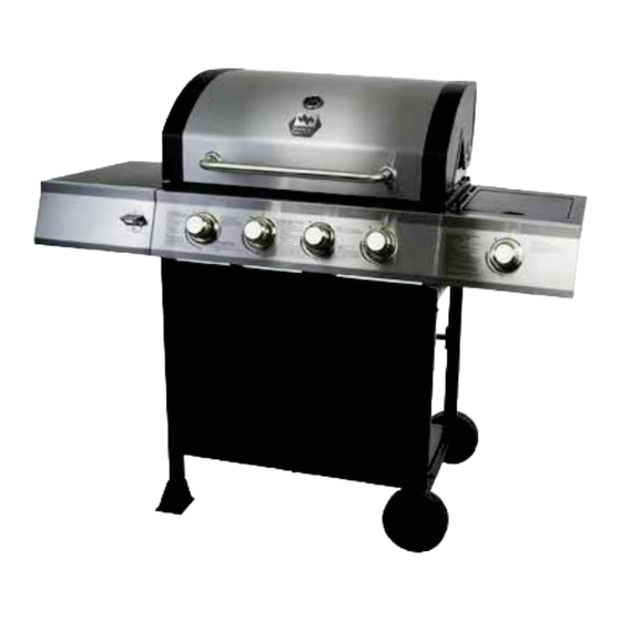
- Page 1 User Manual Manual del usuario 4-BURNER GAS GRILL WITH SIDE BURNER PARILLA DE GAS CON 4 QUEMADORES Y QUEMADOR LATERAL English ..1 Español ..35 ANS Z21.58- 2015 CSA 1.6- 2015 Outdoor Cooking Gas Appliances 70-10-588 Rev. 12/08/16...
- Page 2 Care and Maintenance...
-
Page 3: California Proposition
Safety Information Please read and understand this entire manual before attempting to assemble, operate or install the product. If you have any questions regarding the product, please call customer service at: 1-877-447-4768, 9:00 am - 6:00 pm EST, Monday – Friday. DANGER •... - Page 4 Safety Information WARNING • Do not place the grill under overhead Minimum clearance from sides and back of unit to combustible construction, 36in 36in 914.4mm 36 inches (914.4mm) from sides and 914.4mm back. local codes or, in the absence of local Code, ANSI Z223.1/NFPA 54, Natural B149.1, or Propane Storage and CAUTION...
- Page 5 Package Contents PART DESCRIPTION QUANTITY PART DESCRIPTION QUANTITY Left Leg Assembly Leg End Cap Control Knob Bracket Assembly Cart Front Panel - Upper Left Side Table Assembly Axle Side Burner Bottom Shelf’s Front Bracket Assembly Control Knob Bezel...
- Page 6 Hardware Contents M5x12 ST4.8x10 M10-M6 M6x16 Bolt Wingnut Screw Wrench Bolt Qty. 2 Qty. 2 Qty. 34 Qty. 2 Qty. 2 Qty. 2 M4x10 Washer Bolt Spring Washer Qty. 2 Qty. 2 Qty. 2 Preparation not attempt to assemble the product. Contact customer service for replacement parts. Estimated Assembly Time: Tools Required for Assembly and Leak Testing (not included): CAUTION...
- Page 7 Assembly Instructions Hardware Used ST4.8x10 Screw Slide the axle (X) through the right leg can be used for assembly. Hardware Used M10 Nut M10-M6 Wrench...
- Page 8 Assembly Instructions Use eight M6x16 bolts (DD) to assemble cart front panel - upper (T) and cart front panel - right leg assembly (V). Please note the front Hardware Used M6x16 Bolt Use four M6X16 bolts (DD) to fasten the bottom shelf’s front bracket assembly (Z), bottom shelf’s rear bracket assembly (S) and Hardware Used...
- Page 9 Assembly Instructions Assemble bottom shelf assembly to the left four M6X16 bolts (DD). Hardware Used M6x16 Bolt Bottom Shelf Assembly Use four M6x16 bolts (DD) to fasten the cart assembly. Please note the cart rear support’s M5x12 bolts (EE) to fasten the cylinder block Hardware Used M6x16 Bolt M5x12 Bolt...
- Page 10 Assembly Instructions Assemble the hood handle (A) to the Hardware Used M6 Wingnut M6 Spring Washer M6 Washer Assemble the temp gauge (B) onto the hood. temp gauge (B) onto the hood.
- Page 11 Assembly Instructions Assemble the grill body assembly (C) onto the Hardware Used M6x16 Bolt grill body assembly (C) and do not tighten them the bolt and grill body’s end cap. Then hang the left side table assembly (J) on the bolts three M6x16 bolts (DD) and tighten all bolts.
- Page 12 Assembly Instructions grill body assembly (C) and do not tighten them and make sure to leave a 5mm gap Then hang the right side burner body (M) on the bolts and fasten the right side burner body all bolts. Hardware Used M6x16 Bolt burner valve assembly and control knob bezel (N) to the right side burner body (M).
- Page 13 Assembly Instructions assembled on the side burner (L) and use them to assemble the side burner (L) on the right side burner body (M). positioned inside side burner inlet (venturi). Correct Incorrect Incorrect 2 Bolts previously disassembled side burner sparker. Correct...
- Page 14 Assembly Instructions Put the side burner rack (K) in place.
- Page 15 Assembly Instructions Put the four heat tents (I) into place over each burner.
- Page 16 Assembly Instructions Place grease pan (E) and grease cup (F) in place. Place gas cylinder (sold separately) into the coupling to the threaded valve of the LP gas cylinder. place inside the nesting hole of the Bottom Tank Cylinder...
-
Page 17: Checking For Leaks
Assembly Instructions CHECKING FOR LEAKS • Do not use the grill until any and all leaks are corrected. • If you are unable to correct a leak, disconnect the propane supply and call a gas appliance service dealer. PERFORM LEAK TEST Total solution required is approximately 2 - 3 ounces (70 - 90 ml). -
Page 18: Connecting Gas Cylinder
Operation Instructions CONNECTING GAS CYLINDER Standard of Canada, CAN/CSA-B339, Cylinders, Spheres and Tubes for Transportation of Dangerous Use only 20-pound cylinders (height: 18.11 inches, tank diameter: 9.84 inches, foot diameter: 8.03 inches) ances. The cylinder must include a collar to protect the cylinder valve. The gas cylinder should not be dropped or handled roughly! If the appliance is not in use, the gas cylinder must be disconnected. -
Page 19: Connecting The Lp Tank
Operation Instructions NOTE: for correct cylinder to cylinder holder connection. WARNING ALL INSTRUCTIONS AND SAFEGUARDS ON THIS PAGE MUST BE FOLLOWED TO PREVENT FIRE, DAMAGE AND/OR INJURY. CONNECTING THE LP TANK 2. Check that the control knob on the control unit is turned off. outlet. - Page 20 Operation Instructions Lighting The Grill and odor from the manufacturing process. CAUTION cylinder valve and then TURN OFF the control knob. WARNING Do not lean over grill when lighting. Read instructions before lighting. 1. Check that the control knobs are in the OFF position.
- Page 21 Operation Instructions LIGHTING THE GRILL WITH A MATCH 1. Open the lid. 2. Insert a match in the end of the match holder that is installed on the right leg assembly. 3. Light the match. 4. Immediately place the lit match through the spaces in the grill gates near the ports of the burner position and burner should light immediately.
- Page 22 Care and Maintenance Cooking Grates The best time to ‘burn-off’ the cooking grates is after every use (approx. 15 minutes). The grill is already hot from cooking thus requiring less fuel to obtain necessary temperature for ‘burn-off’. To ‘burn off’ or heat clean your grill, turn the burners to highest position and run for 15 minutes from the grates.
- Page 23 Care and Maintenance Burner Assembly Removing The Burner Assembly 1. Make sure all control knobs are in the OFF Cooking position, gas supply valve is closed, and the gas hose is disconnected from the gas supply. grates, heat tents, clip for burner, ignition chain and main burner.
- Page 24 Care and Maintenance Cleaning the Burner Assembly – Make sure the grill is cool 1.Turn gas off at the control knobs and LP gas cylinder. 2.Disconnect LP gas cylinder from regulator and hose. 4.Detach burner by removing the cotter pins at the back of the burners to detach them from the brackets. 9.Ensure the end of the burner and primary air screen are clear from insect nests, dirt or debris.
- Page 25 Troubleshooting If you have any questions regarding the product, please call customer service at 1-877-447-4768, 9:00 am - 6:00 pm EST, Monday – Friday. PROBLEM POSSIBLE CAUSE CORRECTIVE ACTION The burner will not 1. The igniter electrode may be 1. Clean the ignitor electrode. light using the covered with grease or residue.
-
Page 26: Troubleshooting
Troubleshooting PROBLEM POSSIBLE CAUSE CORRECTIVE ACTION The burner will not 1. Match not reaching burners 1. Use match holder found in light with a match. cabinet door. (when holding match with hand). 2. Empty tank. necessary. 3. Poor connection between 3. - Page 27 Limited Warranty 1-Year Limited Warranty manufacturer (ground shipments, US Mail, or Parcel Post ONLY). Any special handling charges (i.e. customer service. This service is available by calling toll free 1-877-447-4768, 9:00 am - 6:00 pm EST, Monday – Friday. GHP Group Inc. 6440 W.
- Page 28 Replacement Parts List...
-
Page 29: Replacement Parts List
Replacement Parts List For replacement parts, call our customer service department at 1-877-447-4768, 9:00 am - 6:00 pm EST, Monday – Friday. PART DESCRIPTION PART # Temp gauge assembly 70 - 01 - 386 Badge 70 - 10 - 589 70 - 01 - 173 70 - 01 - 272 Cooking grate... - Page 30 For replacement parts, call our customer service department at 1-877-447-4768, 9:00 am - 6:00 pm EST, Monday – Friday. PART DESCRIPTION PART # Axle 70 - 05 - 103 70 - 05 - 104 70 - 09 - 502 Instruction manual 70 - 10 - 588 70-10-588 Printed in China...
Need help?
Do you have a question about the 70-10-588 and is the answer not in the manual?
Questions and answers