Siemens TR300 Manual
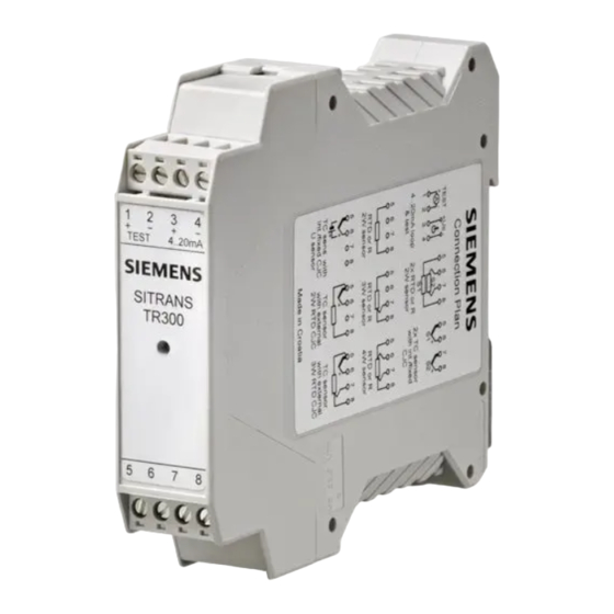
Sitrans rail mount temperature transmitter
Hide thumbs
Also See for TR300:
- Compact operating instructions (188 pages) ,
- Operating instructions manual (82 pages) ,
- Compact operating instructions (186 pages)
Table of Contents
Advertisement
Quick Links
Advertisement
Table of Contents

Subscribe to Our Youtube Channel
Related Manuals for Siemens TR300


Summary of Contents for Siemens TR300
- Page 1 P R O D U C T I N S T R U C T I O N MA N U A L V 1 . 0 MA Y 2 0 1 6 S I T R A N S R A I L MO U N T T E MP E R A T U R E T R A N S MI T T E R MO D E L S : T R 3 0 0 2 0 1 S O U T H H O U S T O N A V E .
- Page 2 ___________________ SITRANS TR200/TR300 Introduction ___________________ General safety notes ___________________ Description SITRANS ___________________ Installation Temperature transmitter ___________________ SITRANS TR200/TR300 Connecting ___________________ Operation Operating Instructions ___________________ Functional safety ___________________ Commissioning ___________________ Functions ___________________ Service and maintenance ___________________ Technical data ___________________ Dimension drawings...
- Page 3 Note the following: WARNING Siemens products may only be used for the applications described in the catalog and in the relevant technical documentation. If products and components from other manufacturers are used, these must be recommended or approved by Siemens. Proper transport, storage, installation, assembly, commissioning, operation and maintenance are required to ensure that the products operate safely and without any problems.
-
Page 4: Table Of Contents
Connector pin assignment ......................24 Connection diagrams ........................25 5.4.1 Sensor/input ..........................25 5.4.2 Auxiliary power supply/current loop 4 to 20 mA and test terminals ..........27 5.4.3 Coding profiles ..........................27 Notes on measuring current......................28 Test terminals for output signal....................28 SITRANS TR200/TR300 Operating Instructions, 06/2010, A5E01071992-03... - Page 5 Table of contents Operation..............................29 Operating and parameterizing the SITRANS TR200/TR300 ............29 Operating the with SITRANS TR200 PC/laptop and modem ............. 29 SITRANS TR300 operation......................31 6.3.1 Operation using a HART modem and SIMATIC PDM ..............31 6.3.2 Operation with HART communicator ..................32 Functional safety............................
- Page 6 Operating hours counter in temperature classes.................61 Slave pointer ..........................62 9.19 9.20 Simulation (only for SITRANS TR300) ..................63 9.21 Individual password protection (SITRANS TR300 only) ..............65 Service and maintenance ........................67 Technical data ............................69 11.1 Technical data..........................69 11.2 Digital measuring error.........................76 Dimension drawings ..........................
- Page 7 Table of contents SITRANS TR200/TR300 Operating Instructions, 06/2010, A5E01071992-03...
-
Page 8: Introduction
Installation path for PDM identification nameplate FW: 01.01.05 TR200: SIPROM T V1.2.0 TR200: Not applicable 04/2007 HW: 01.00 TR300: PDM V6.0 TR300: SITRANS TR300 DD Rev. 1.00 FW: 01.01.05 TR200: SIPROM T V1.2.1 TR200: Not applicable 09/2008 HW: 01.02 TR300: PDM V6.0 TR300: SITRANS TR300 DD Rev. -
Page 9: Notes On Warranty
The contents of this programming manual shall not become part of or modify any prior or existing agreement, commitment or legal relationship. All obligations on the part of Siemens AG are contained in the respective sales contract, which also contains the complete and solely applicable warranty conditions. -
Page 10: General Safety Notes
● For explosion-proof devices: They are authorized, trained, or instructed in carrying out work on electrical circuits for hazardous systems. ● They are trained or instructed in maintenance and use of appropriate safety equipment according to the safety regulations. SITRANS TR200/TR300 Operating Instructions, 06/2010, A5E01071992-03... -
Page 11: Laws And Directives
● Canadian Electrical Code (CEC) (Canada) ● The working reliability regulation (Germany) Further provisions for hazardous areas, these are for example: ● IEC 60079-14 (international) ● EN 60079-14 (formerly VDE 0165, T1) (EU, Germany) See also Certificates (http://www.siemens.com/processinstrumentation/certificates) SITRANS TR200/TR300 Operating Instructions, 06/2010, A5E01071992-03... -
Page 12: Measures
The damage to a module caused by overvoltage cannot normally be detected immediately, it only becomes apparent after a longer period of operating time has elapsed. SITRANS TR200/TR300 Operating Instructions, 06/2010, A5E01071992-03... - Page 13 General safety notes 2.5 Measures SITRANS TR200/TR300 Operating Instructions, 06/2010, A5E01071992-03...
-
Page 14: Description
Description Application range The SITRANS TR200 and SITRANS TR300 temperature transmitters are 2-wire devices for DIN rail installation. They are suitable for use in all sectors, thanks to their universal sensor input and type of installation. The following sensor and signal sources can be connected to their input stage: ●... -
Page 15: Structure Of The Nameplate
⑫ Description Marking (TAG) ⑬ ⑭ Ex marking with EX data Place of manufacture ⑮ ⑯ Firmware revision Hardware revision ⑰ Communications Figure 3-1 Layout of a nameplate using SITRANS TR200 as an example SITRANS TR200/TR300 Operating Instructions, 06/2010, A5E01071992-03... -
Page 16: Operating Principle
⑦ Auxiliary power supply Output current Test Test terminals for temporary connection of an amperemeter Figure 3-2 SITRANS TR200/TR300 function block diagram Mode of operation of transmitters ① ● The sensor supplies an electrical signal ② ● This signal is converted to a digital signal in an analog-to-digital converter ③... -
Page 17: Communication
TR200 can only be set in the "Offline" state using the modem for SITRANS TH100/TH200/TR200. SITRANS TR300 The device has a parameter assignment interface according to the HART specification. This parameterization interface permits access to all the functions of the device via a HART modem or a HART communicator. -
Page 18: Hart Communication With Supply From A Voltage Source
Description 3.5 Communication 3.5.2 HART communication with supply from a voltage source Figure 3-3 HART communication with supply from a voltage source SITRANS TR200/TR300 Operating Instructions, 06/2010, A5E01071992-03... -
Page 19: Hart Communication With Supply From A Feed Splitter
Load ≥ 250 Ω is relevant only if HART communication is performed via this branch. Otherwise for variant ① ② load 0 to 650 Ω Figure 3-4 HART communication with supply from a feed splitter SITRANS TR200/TR300 Operating Instructions, 06/2010, A5E01071992-03... -
Page 20: Installation
IP6X degree of protection. CAUTION Electromagnetic Compatibility If the sensor is installed outside a closed building, you must check the transmitter for correct functioning following a lightning stroke. SITRANS TR200/TR300 Operating Instructions, 06/2010, A5E01071992-03... - Page 21 Installation SITRANS TR200/TR300 Operating Instructions, 06/2010, A5E01071992-03...
-
Page 22: Connecting
Avoid getting too close to large electrical systems and/or use shielded cables. Use shielded cables to ensure the full specification according to HART, revision 5.9 in SITRANS TR300. Use only cable entries and covers that are approved for the relevant use. -
Page 23: Safety Notes When Connecting In Hazardous Areas
60 V. Be sure to observe the construction directives valid at the construction location for electrical resources in hazardous areas. In Europe, this is the standard EN 60079-14. SITRANS TR200/TR300 Operating Instructions, 06/2010, A5E01071992-03... - Page 24 Additional requirements for use in dust explosion protected areas Install the transmitter in an enclosure suitable for the respective type of dust and corresponding Zone in accordance with the inspection certificate valid in your country. SITRANS TR200/TR300 Operating Instructions, 06/2010, A5E01071992-03...
-
Page 25: Connecting The Auxiliary Power Supply
Test terminals (test) for measuring the output current using an amperemeter 3 (+) and 4 (-) Auxiliary power supply U , output current I 5, 6, 7 and 8 Connection of sensors, see terminal diagrams SITRANS TR200/TR300 (Page 25) Figure 5-1 Connector pin assignment SITRANS TR200/TR300 SITRANS TR200/TR300... -
Page 26: Connection Diagrams
Cold junction compensation Calculation of mean value/ compensation/fixed value with external Pt100 in two- with external Pt100 in three- differential value with internal wire input wire input cold junction compensation Line resistance for correction is programmable. SITRANS TR200/TR300 Operating Instructions, 06/2010, A5E01071992-03... - Page 27 Connecting 5.4 Connection diagrams Voltage measurement Current measurement See also Connector pin assignment (Page 24) SITRANS TR200/TR300 Operating Instructions, 06/2010, A5E01071992-03...
-
Page 28: Auxiliary Power Supply/Current Loop 4 To 20 Ma And Test Terminals
Auxiliary power supply/current loop 4 to 20 mA and test terminals Test terminals (Test) Auxiliary power supply connection/4 to 20 mA 5.4.3 Coding profiles Coding profile for SITRANS TR200/TR300 Coding profile for SITRANS TR200/TR300 with protection against explosions (intrinsically safe) without protection against explosions 4 3 2 1... -
Page 29: Notes On Measuring Current
If during current measurement the measured values are called up via the digital interface, such as HART for SITRANS TR300, the measurement data are shown in the operating software as voltage signals mV units. The voltage signals are scaled by the factor of the externally connected resistance value R. -
Page 30: Operation
The SITRANS TR200 and SITRANS TR300 are operated and configured using a PC. The PC is connected to the two-wire line using a suitable coupling module. The SITRANS TR300 can also be parameterized using a HART communicator. The signals needed for SITRANS TR300 communications in accordance with the HART protocol are superimposed on the output current in accordance with frequency shift keying. - Page 31 For detailed information on parameter assignment of the transmitter, refer to the operating instructions for the following products: ● Modem for SITRANS TH100/TH200/TR200 and the SIPROM T parameterization software; order numbers: 7NG3092-8KM and 7NG3092-8KU ● "sitrans t - temperature transmitters" CD, order number A5E00364512 SITRANS TR200/TR300 Operating Instructions, 06/2010, A5E01071992-03...
-
Page 32: Sitrans Tr300 Operation
Operation 6.3 SITRANS TR300 operation SITRANS TR300 operation 6.3.1 Operation using a HART modem and SIMATIC PDM The transmitter can be operated and parameterized with the PC, using the SIMATIC PDM parameter assignment software and a HART modem. Commissioning procedure ●... -
Page 33: Operation With Hart Communicator
Operation 6.3 SITRANS TR300 operation 6.3.2 Operation with HART communicator Action buttons This button switches the HART communicator on and off. After switch-on, the hand-held terminal automatically establishes communication with the transmitter. The online menu appears on the display. This button moves the cursor up through the menu bar. The selected menu line is indicated. -
Page 34: Functional Safety
Description The sensor, logic unit/control system and final controlling element combine to form a safety- instrumented system, which executes a safety function. Failure signal Figure 7-1 Example of a safety-instrumented system SITRANS TR200/TR300 Operating Instructions, 06/2010, A5E01071992-03... - Page 35 In case of a fault, the control system generates a failure signal of < 3.6 mA or > 22 mA for the connected positioner, which switches the associated valve to the specified safety position. SITRANS TR200/TR300 Operating Instructions, 06/2010, A5E01071992-03...
-
Page 36: Safety Integrity Level (Sil)
60 to 90 % SIL 1 SIL 2 SIL 3 90 to 99 % SIL 2 SIL 3 SIL 4 > 99 % SIL 3 SIL 4 SIL 4 As per IEC 61511-1, Section 11.4.4 SITRANS TR200/TR300 Operating Instructions, 06/2010, A5E01071992-03... - Page 37 ● The configuration level of the firmware is blocked against unauthorized operation. ● The function requires SIL of less than 4. The device fulfills these conditions. SITRANS TR200/TR300 Operating Instructions, 06/2010, A5E01071992-03...
-
Page 38: Device-Specific Safety Instructions
● Functional safety to SIL 2 under IEC 61508 or IEC 61511-1, from firmware version FW: as of 1/1/2005 (with order option C20 only) ● Explosion protection for corresponding versions ● Electromagnetic compatibility in compliance with EN 61326 ● EC Declaration of Conformity SITRANS TR200/TR300 Operating Instructions, 06/2010, A5E01071992-03... -
Page 39: Settings
You check the measuring accuracy, for example, with a sensor calibration. Note Configuration changes in SITRANS TR300 not protected by passwords If there is no password protection, you may have to deal with undesirable changes in the configuration of the device. -
Page 40: Behavior In Case Of Faults
When ordering replacement devices, please specify the serial number of the original device. The serial number can be found on the rating plate. The address of the responsible SIEMENS repair center, contacts, spare parts lists, etc. can be found on the Internet. -
Page 41: Safety Characteristics
40 °C for an extended period of time. ● The calculation of error rates is based on a MTTR of 72 hours. The maximum application time of the SITRANS TR200 or TR300 in a safety application is 20 years. Replace the device after this time. -
Page 42: Commissioning
– Constant red light: Indication of errors in the device, e.g. RAM-, ROM-, EEPROM-, CHECKSUM-, WATCHDOG-, STACK error or violation of the permitted ambient temperature limits and if the minimum supply voltage for the device is not reached. SITRANS TR200/TR300 Operating Instructions, 06/2010, A5E01071992-03... - Page 43 Commissioning 8.2 LED operating indicator SITRANS TR200/TR300 Operating Instructions, 06/2010, A5E01071992-03...
-
Page 44: Functions
Functions General information You can operate the SITRANS TR300 using either the SIMATIC PDM parameterization software or the HART communicator. You can operate the SITRANS TR200 using the SIPROM T parameterization software. The following functions are available to you when operating the SITRANS TR300/TR200: ●... - Page 45 SITRANS TR300 from 4 to 20 mA – Factory reset: Resetting the operating data to the factory settings – Simulation of measurement input. Only for SITRANS TR300: Simulation of signal input, analog output, and electronics temperature – Only for SITRANS TR300: Individual password protection The operating data is stored in a non-volatile memory (EEPROM).
-
Page 46: Broken Wire Monitoring
● Rising characteristic: Full scale value is greater than start of scale value. ● Falling characteristic: Full scale value is less than start of scale value. SITRANS TR200/TR300 Operating Instructions, 06/2010, A5E01071992-03... -
Page 47: Measured Value Offset
● External with Pt100: an external Pt100 measures the cold junction temperature in this version. You can connect the Pt100 to the transmitter in two-wire or three-wire input. The cold junction is compensated on the basis of the current temperature of the external Pt100. SITRANS TR200/TR300 Operating Instructions, 06/2010, A5E01071992-03... -
Page 48: Calculation Of Differential Value/Mean Value
You can set the filter time constant of electrical damping to a point within a range from 0 to 30 s. 9.11 Current transmitter function (only for SITRANS TR300) You can use this function to switch the transmitter into constant current mode for test purposes. In that case, the output current no longer corresponds to the process variable. -
Page 49: Alarm Current
Recommended setting range for lower fault current range and lower control range limit ⑦ Recommended setting range for upper fault current range and upper control range limit Figure 9-1 Current limits with output signal 4 to 20 mA SITRANS TR200/TR300 Operating Instructions, 06/2010, A5E01071992-03... -
Page 50: 9.13 Sensor Calibration
● Use the operating software to command the transmitter to load this process value. SITRANS TR200 uses SIPROM T operating software, SITRANS TR300 uses SIMATIC PDM operating software or the HART communicator. - Page 51 Figure 9-2 Sensor calibration Note If any of the following device parameters is changed by re-parameterization, a two point sensor calibration of SITRANS TR200/TR300 performed specifically for a customer is automatically reset: Sensor class Sensor type Interface ...
-
Page 52: Current Sensor Calibration (D/A Trim)
B→C: Change in gradient trim 4 mA C Characteristic curve after current transmitter trim 20 mA Figure 9-3 Current transmitter trim See also Application example: Current input calibration at 4 mA and 20 mA (Page 52) SITRANS TR200/TR300 Operating Instructions, 06/2010, A5E01071992-03... -
Page 53: Application Example: Current Input Calibration At 4 Ma And 20 Ma
2. Read the measured value at the ammeter. 3. Enter the measured current value using the operating software. The transmitter uses this value for gradient correction of the current. The value for 4 mA is not affected by this. SITRANS TR200/TR300 Operating Instructions, 06/2010, A5E01071992-03... -
Page 54: Special Characteristic Curve
The maximum number of sampling points is restricted to 30 pairs of values. The individual pairs of values are entered as a percentage of the set measuring span. Figure 9-4 Principle of customer-specific characteristic curve correction SITRANS TR200/TR300 Operating Instructions, 06/2010, A5E01071992-03... - Page 55 ● The x-values must rise monotonously when the characteristic curve is input, the y-values must rise or fall monotonously. ● The x-values do not have to be input in equidistant intervals. SITRANS TR200/TR300 Operating Instructions, 06/2010, A5E01071992-03...
- Page 56 0 °C 15 mV i = 4 50 % 55 % 175 °C 35 mV i = 5 90 % 95 % 375 °C 40 mV i = 6 100 % 100 % 400 °C SITRANS TR200/TR300 Operating Instructions, 06/2010, A5E01071992-03...
- Page 57 The following pair of values must be transferred to the parameter assignment software for the characteristic curve correction of the pair of values i = 3: X[3] = 20 % and Y[3] = 20 %. SITRANS TR200/TR300 Operating Instructions, 06/2010, A5E01071992-03...
-
Page 58: Factory Parameters
Are all reset to 0 h Runtime meters, field device Are not reset Min/max pointers PV Are all reset to 0 Min/max pointers for electronics temperature Are not reset Manufacturer data sensor Are not reset SITRANS TR200/TR300 Operating Instructions, 06/2010, A5E01071992-03... -
Page 59: Diagnostics
9.17.1 Diagnostics functions The diagnostic concept of the SITRANS TR200 and the SITRANS TR300 envisages that a diagnostic warning can be set in the parameters for diagnostic functions that are used for monitoring limit values. A diagnostic interrupt can be set in the parameters for diagnostic functions that are used for monitoring error conditions. - Page 60 Functions 9.17 Diagnostics Diagnostics warnings Diagnostic warnings are output via: ● HART communication, only for SITRANS TR300 The device transmits the diagnostics event that has occurred via the operating software. The analog output value is unchanged. Diagnostics function Priority HART...
-
Page 61: Violations Of Specification
Use the software tool SIPROM T or SIMATIC PDM to carry out the reset: SIPROM T menu item for SITRANS TR200: Device ➜ Device status ➜ Device reset after ambient temperature error SIMATIC PDM menu item for SITRANS TR300: View ➜ Device status ➜ Device reset after ambient temperature error Note... -
Page 62: Operating Hours Counter In Temperature Classes
– Sensor factor The parameter assignment software SIPROM T for SITRANS TR200 or SIMATIC PDM or HART communicator on SITRANS TR300 can read out the operating hours counters. The operating hours counters are automatically stored to the non-volatile memory once an hour. -
Page 63: Slave Pointer
Resetting the min/max pointer is only possible for the measured value. A reset is performed: ● At the user's request ● Automatically when any of the following parameters is changed in the device: – Sensor class – Sensor type – Interface – Sensor connection – Sensor factor SITRANS TR200/TR300 Operating Instructions, 06/2010, A5E01071992-03... -
Page 64: Simulation (Only For Sitrans Tr300)
Functions 9.20 Simulation (only for SITRANS TR300) 9.20 Simulation (only for SITRANS TR300) With the "Simulation" diagnostic function, you can receive and process (quasi-) measurement data without having a process value at the device. This allows you to run individual process operations in the "cold" state and thus simulate process states. In addition, you can check the wire layout for the analog output by adding on the simulation values. - Page 65 Functions 9.20 Simulation (only for SITRANS TR300) Measuring input simulation Note Simulation The transmitter does not respond to sensor input signals when the simulation is active. The device may not be parameterized to "thermocouple with internal cold-junction compensation" for simulating the internal electronics temperature. In this case, the internal electronics temperature is a measured variable and cannot be replaced by a simulation value.
-
Page 66: Individual Password Protection (Sitrans Tr300 Only)
Store your new password in a secure location. Consult the Siemens contact person in your region to receive your "super pin". When you activate the password protection in the device, write protection will be set automatically after the device has been switched on. - Page 67 Functions 9.21 Individual password protection (SITRANS TR300 only) SITRANS TR200/TR300 Operating Instructions, 06/2010, A5E01071992-03...
-
Page 68: Service And Maintenance
Service and maintenance The transmitter is maintenance-free. SITRANS TR200/TR300 Operating Instructions, 06/2010, A5E01071992-03... - Page 69 Service and maintenance SITRANS TR200/TR300 Operating Instructions, 06/2010, A5E01071992-03...
-
Page 70: Technical Data
Can be switched on/off (default value = ON) Measuring range Can be set in the parameters (see table in chapter Digital measuring error (Page 76)) Min. measuring span 10 °C (18 °F) Characteristic curve Linear to temperature or special characteristic curve SITRANS TR200/TR300 Operating Instructions, 06/2010, A5E01071992-03... - Page 71 Digital measuring error (Page 76)) Min. measuring span 5 or 25 Ω (see table in chapter Digital measuring error (Page 76)) Characteristic curve Linear to resistance or special characteristic curve Prerequisites: same resistance for all three lines. SITRANS TR200/TR300 Operating Instructions, 06/2010, A5E01071992-03...
- Page 72 Can be set in the parameters Min. measuring span Min. 40 ... 100 °C (72 ... 180 °F) (see table in chapter Digital measuring error (Page 76)) Characteristic curve Linear to temperature or special characteristic curve SITRANS TR200/TR300 Operating Instructions, 06/2010, A5E01071992-03...
- Page 73 Linear to voltage or special characteristic curve Output Output signal 4 ... 20 mA, two-wire line With SITRANS TR300, additionally with communication according to HART rev. 5.9 Auxiliary power supply 11 ... 35 V DC (to 30 V in Ex "i"/"ic"; to 32 V with Ex "nA")
- Page 74 < 0.02 % of the measuring span in the first Long-term drift (start of scale value, measuring month span) < 0.2 % of the span after one year < 0.3 % of the span after five years SITRANS TR200/TR300 Operating Instructions, 06/2010, A5E01071992-03...
- Page 75 II 3(1) G Ex ia/ic IIC T6/T4 II 3 G Ex ic IIC T6/T4 II 2(1) D Ex iaD/ibD 20/21 T115 °C II 3 G Ex nA II T6/T4 Type of protection "Non-sparking resources" SITRANS TR200/TR300 Operating Instructions, 06/2010, A5E01071992-03...
- Page 76 11.1 Technical data Factory setting Factory setting Pt100 (IEC 751) In three-wire input Measuring range 0 ... 100 °C (32 ... 212 °F) Fault current 22.8 mA Sensor offset 0 °C (0 °F) Attenuation 0.0 s SITRANS TR200/TR300 Operating Instructions, 06/2010, A5E01071992-03...
-
Page 77: 11.2 Digital Measuring Error
-60 ... +250 (-76 ... +482) 10 (18) 0,1 (0.18) Digital measuring errors for resistance-type transmitters Input point Measuring range Minimum span in [Ω] Digital accuracy [Ω] [Ω] Resistance 0 ... 390 0,05 Resistance 0 ... 2200 0,25 SITRANS TR200/TR300 Operating Instructions, 06/2010, A5E01071992-03... - Page 78 50 (90) 2 (3.6) Digital measuring errors for millivolt transmitters Input point Measuring range in mV Minimum measuring Digital accuracy in μV span in mV Millivolt transmitter -10 ... +70 Millivolt transmitter -100 ... +1100 SITRANS TR200/TR300 Operating Instructions, 06/2010, A5E01071992-03...
- Page 79 Technical data 11.2 Digital measuring error SITRANS TR200/TR300 Operating Instructions, 06/2010, A5E01071992-03...
-
Page 80: Dimension Drawings
For electrical data see PTB 07 ATEX 2032 X WARNING: POTENTIAL ELECTROSTATIC CHARGING HAZARD - SEE INSTRUCTIONS ! WARNUNG: GEFAHR DURCH ELEKTRO- STATISCHE ENTLADUNGEN - SIEHE BETRIEBSANLEITUNG ! TAG: Range: Description: Type: Message: Error: Figure 12-1 SITRANS TR200/TR300 dimensional drawing SITRANS TR200/TR300 Operating Instructions, 06/2010, A5E01071992-03... - Page 81 Dimension drawings SITRANS TR200/TR300 Operating Instructions, 06/2010, A5E01071992-03...
-
Page 82: Spare Parts And Accessories
With explosion protection according to ATEX type of protection 7NG3032-1JN00 "Intrinsic safety" Ex ia/ib/ic, non-sparking (nA) SITRANS TR300 temperature transmitter for installation on DIN rails, two-wire technology 4 to 20 mA, HART, with electrical isolation, with documentation on CD Without explosion protection ... - Page 83 Spare parts and accessories SITRANS TR200/TR300 Operating Instructions, 06/2010, A5E01071992-03...
-
Page 84: Appendix
Appendix Certificates You can find the certificates on the "sitrans t - temperature transmitters" CD, available separately, order no. A5E00364512; and on the Internet. See also Certificates (http://www.siemens.com/processinstrumentation/certificates) SITRANS TR200/TR300 Operating Instructions, 06/2010, A5E01071992-03... -
Page 85: Technical Support
● Information about field service, repairs, spare parts and lots more under "Services." Additional Support Please contact your local Siemens representative and offices if you have any questions about the products described in this manual and do not find the right answers. -
Page 86: List Of Abbreviations
It consists of a sensor, logic unit/control system and final controlling element. Test Interval Testing interval of the protective function SITRANS TR200/TR300 Operating Instructions, 06/2010, A5E01071992-03... - Page 87 List of abbreviations B.1 Abbreviations SITRANS TR200/TR300 Operating Instructions, 06/2010, A5E01071992-03...
-
Page 88: Glossary
Representation of a variable, e.g. time, in the form of characters or numbers. In its digital representation, this variable can be changed only in pre-defined steps. In contrast to "Analog". Deutsches Institut für Normung e. V. - German institute for standardization SITRANS TR200/TR300 Operating Instructions, 06/2010, A5E01071992-03... - Page 89 Failure/Fault Failure: A resource is no longer capable of executing a required function. Fault: Undesired state of a resource indicated by the incapability of executing a required function. Fault Failure/Fault → SITRANS TR200/TR300 Operating Instructions, 06/2010, A5E01071992-03...
- Page 90 Standardized parameter sets can be used for the manufacture-independent operation of all HART devices. Typical applications include transmitters for measuring mechanical and electrical dimensions. International Protection = international degree of protection SITRANS TR200/TR300 Operating Instructions, 06/2010, A5E01071992-03...
- Page 91 It consists of a sensor, logic unit/control system and final controlling element. Example: A safety-instrumented system is made up of a pressure transmitter, a limit signal sensor and a control valve. SITRANS TR200/TR300 Operating Instructions, 06/2010, A5E01071992-03...
- Page 92 ● Average probability of dangerous failure of a safety function in case of demand (PFD ● Hardware fault tolerance (HFT) ● Safe failure fractions (SFF) The Universal Serial Bus (USB) is a serial bus system for connecting a PC/laptop to external devices such as: modems. SITRANS TR200/TR300 Operating Instructions, 06/2010, A5E01071992-03...
- Page 93 Glossary SITRANS TR200/TR300 Operating Instructions, 06/2010, A5E01071992-03...
-
Page 94: Index
Control system, 33 Correct usage, 9 Coupling module, 29 Current measurement, 28 Internet, 84 Current output calibration, 52 Intrinsic safety, 11 Customer Support Hotline, 84 LED operating indicator, 41 Diagnostics Interrupt, 58 LED, 60 Warning, 58 SITRANS TR200/TR300 Operating Instructions, 06/2010, A5E01071992-03... - Page 95 Intrinsic safety, 11 Non-sparking nA (Zone 2), 11 Qualified personnel, 9 Zone 2, 11 Recycling, 8 Resistance, 21 Safety Checking, 39 Safety function Checking, 38, 39 Sensor, 33 Sensor calibration, 38 sensor calibration point SITRANS TR200/TR300 Operating Instructions, 06/2010, A5E01071992-03...
- Page 96 S I E ME N S ® S I T R A N S R A I L MO U N T T E MP E R A T U R E T R A N S MI T T E R MO D E L S : T R 3 0 0 E R N I E G R A V E S S E R V I C E A N D S U P P O R T E E r n i e G r a v e s i s c o mmi t t e d t o a s s u r i n g a l l o f o u r c u s t o me r s r e c e i v e t h e i d e a l f l o w s o l u t i o n f o r t h e i r a p p l i c a t i o n ,...
Need help?
Do you have a question about the TR300 and is the answer not in the manual?
Questions and answers