Siemens SITRANS TH100 Operating Instructions Manual
Temperature transmitter
Hide thumbs
Also See for SITRANS TH100:
- Operating instructions manual (236 pages) ,
- Compact operating instructions (188 pages) ,
- Compact operating instructions (187 pages)
Table of Contents
Advertisement
Quick Links
SITRANS TH100
SITRANS T
Temperature transmitter
SITRANS TH100
Operating Instructions
7NG3211-0*N00 SITRANS TH100
06/2010
A5E00331168-02
___________________
Introduction
___________________
General safety information
___________________
Description
___________________
Assembly
___________________
Connecting
___________________
Operation
___________________
Commissioning
___________________
Functions
___________________
Service and maintenance
___________________
Technical data
___________________
Dimensional drawings
___________________
Spare parts and accessories
___________________
Appendix
1
2
3
4
5
6
7
8
9
10
11
12
A
Advertisement
Table of Contents

Related Manuals for Siemens SITRANS TH100


Summary of Contents for Siemens SITRANS TH100
- Page 1 SITRANS T ___________________ Assembly Temperature transmitter ___________________ SITRANS TH100 Connecting ___________________ Operation Operating Instructions ___________________ Commissioning ___________________ Functions ___________________ Service and maintenance ___________________ Technical data ___________________ Dimensional drawings ___________________ Spare parts and accessories ___________________ Appendix 7NG3211-0*N00 SITRANS TH100 06/2010 A5E00331168-02...
- Page 2 Note the following: WARNING Siemens products may only be used for the applications described in the catalog and in the relevant technical documentation. If products and components from other manufacturers are used, these must be recommended or approved by Siemens. Proper transport, storage, installation, assembly, commissioning, operation and maintenance are required to ensure that the products operate safely and without any problems.
-
Page 3: Table Of Contents
5.1.1 General safety notes on the connection ..................19 5.1.2 Safety notes when connecting in hazardous areas ..............20 Connecting the auxiliary power supply ..................23 Connector assignments .......................23 Connection diagrams ........................24 Operation..............................25 Commissioning ............................27 SITRANS TH100 Operating Instructions, 06/2010, A5E00331168-02... - Page 4 Type of characteristic curve (rising or falling) ................30 Service and maintenance ........................31 Technical data ............................33 Dimensional drawings..........................37 11.1 Dimension drawing for SITRANS TH100..................37 11.2 Dimension drawing for the DIN rail adapter ................37 Spare parts and accessories ........................39 Appendix..............................41 Certificates ..........................
-
Page 5: Introduction
The contents of this programming manual shall not become part of or modify any prior or existing agreement, commitment or legal relationship. All obligations on the part of Siemens AG are contained in the respective sales contract, which also contains the complete and solely applicable warranty conditions. -
Page 6: Environmental Protection
Devices described in this programming manual can be recycled owing to the low content of noxious substances in their version. Please contact a certified waste disposal company for eco-friendly recycling and to dispose of your old devices. SITRANS TH100 Operating Instructions, 06/2010, A5E00331168-02... -
Page 7: General Safety Information
● For explosion-proof devices: They are authorized, trained, or instructed in carrying out work on electrical circuits for hazardous systems. ● They are trained or instructed in maintenance and use of appropriate safety equipment according to the safety regulations. SITRANS TH100 Operating Instructions, 06/2010, A5E00331168-02... -
Page 8: Laws And Directives
● Canadian Electrical Code (CEC) (Canada) ● The working reliability regulation (Germany) Further provisions for hazardous areas, these are for example: ● IEC 60079-14 (international) ● EN 60079-14 (formerly VDE 0165, T1) (EU, Germany) See also Certificates (http://www.siemens.com/processinstrumentation/certificates) SITRANS TH100 Operating Instructions, 06/2010, A5E00331168-02... -
Page 9: Measures
The damage to a module caused by overvoltage cannot normally be detected immediately, it only becomes apparent after a longer period of operating time has elapsed. SITRANS TH100 Operating Instructions, 06/2010, A5E00331168-02... - Page 10 General safety information 2.5 Measures SITRANS TH100 Operating Instructions, 06/2010, A5E00331168-02...
-
Page 11: Description
Description Field of application The SITRANS TH100 transmitter can be used in all fields. Its compact size means that it can be installed in connection heads of type B (DIN 43729) or larger. The following sensor can be connected: ● Pt100 resistance thermometer The output signal is a load-independent direct current of 4 to 20 mA which is proportional to the temperature. -
Page 12: Nameplate Structure
Information about explosion protection With explosion-proof devices, the information about explosion protection is noted on an additional plate on the enclosure. Information regarding the certified types of protection can be found in Chapter Technical data (Page 33): SITRANS TH100 Operating Instructions, 06/2010, A5E00331168-02... -
Page 13: Mode Of Operation
Figure 3-2 Function block diagram SITRANS TH100 Mode of operation of the transmitter The signal delivered by a Pt100 resistance thermometer (two-wire, three-wire, four-wire system) is amplified in the input stage. The voltage proportional to the input variable is then converted into digital signals by a multiplexer in an analog-to-digital converter. - Page 14 Description 3.4 Mode of operation SITRANS TH100 Operating Instructions, 06/2010, A5E00331168-02...
-
Page 15: Assembly
The transmitter is either secured in the base of the connection head or in the raised cover of the connection head. Included in the transmitter's scope of delivery are: ● Springs ● Fixing screws SITRANS TH100 Operating Instructions, 06/2010, A5E00331168-02... - Page 16 4.2 Installation in the connection head Securing the transmitter in the connection head base ① ② Transmitter Connection head Securing the transmitter in the connection head cover ① ② Transmitter Ceramic base of the measuring element ③ Connection head SITRANS TH100 Operating Instructions, 06/2010, A5E00331168-02...
-
Page 17: Installation On Din Rail And G Rail
Order No. 7NG3092-8KA. Adhere to the ambient conditions specified in the technical data. Figure 4-1 Securing the transmitter on DIN rails Figure 4-2 Securing the transmitter on G rails SITRANS TH100 Operating Instructions, 06/2010, A5E00331168-02... - Page 18 Assembly 4.3 Installation on DIN rail and G rail SITRANS TH100 Operating Instructions, 06/2010, A5E00331168-02...
-
Page 19: Connecting
At an ambient temperature T ≥ 60°C, use heat-resistant cables approved for an ambient temperature of at least 20 K higher. Use cables with wires that have a maximum cross-sectional area of 2.5 mm SITRANS TH100 Operating Instructions, 06/2010, A5E00331168-02... -
Page 20: Safety Notes When Connecting In Hazardous Areas
"Intrinsic safety" is no longer guaranteed and the intrinsically-safe approval may be revoked. Permanently erase, therefore, the irrelevant types of protection on the nameplate before commissioning to ensure that erroneous deployment is avoided. SITRANS TH100 Operating Instructions, 06/2010, A5E00331168-02... - Page 21 = 750 mW = 106 μH = 7.3 nF Maximum values of the sensor circuit with type of protection nL, ic or nA[ic] = 9.6 V DC: = 7.6 mA = 12.5 mW [mH] [nF] 1250 SITRANS TH100 Operating Instructions, 06/2010, A5E00331168-02...
- Page 22 Additional requirements for use in dust explosion protected areas Install the transmitter in an enclosure suitable for the respective type of dust and corresponding Zone in accordance with the inspection certificate valid in your country. SITRANS TH100 Operating Instructions, 06/2010, A5E00331168-02...
-
Page 23: Connecting The Auxiliary Power Supply
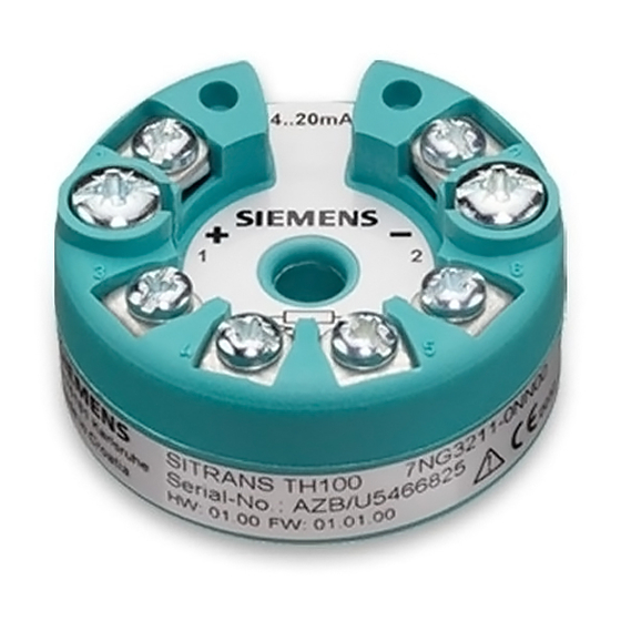
Fixing screws for cables 1 to 6 Connections: 1 (+) and 2 (-) Auxiliary power supply U , output current I 3, 4, 5, and 6 Sensor connections (Pt100) Figure 5-1 Connector assignments SITRANS TH100 SITRANS TH100 Operating Instructions, 06/2010, A5E00331168-02... -
Page 24: Connection Diagrams
Terminal No. 5 has no function in the version with three-wire input, and must not be connected. When using RTDs in a version with four-wire input but when selecting a three-wire input, the cores of the unused fourth sensor line must be electrically insulated using tape. SITRANS TH100 Operating Instructions, 06/2010, A5E00331168-02... -
Page 25: Operation
NOTICE Parameter assignment Parameters may only be assigned to the SITRANS TH100 in the "offline" state using the parameter assignment modem and the SIPROM T operating software. Any 4 to 20 mA current loop connected to the transmitter must be disconnected before parameters are assigned. - Page 26 Operation Parameter assignment to SITRANS TH100 via USB modem Parameter assignment to SITRANS TH100 via RS232 modem SIEMENS SIEMENS For more detailed information on assigning parameters to the transmitter, refer to the operating instructions for the following products: ● Modem for SITRANS TH100/TH200/TR200 and the SIPROM T parameterization software;...
-
Page 27: Commissioning
5. Wait about 10 seconds. After this start-up time the transmitter is operational. Note Warming-up To obtain exact measured values, the transmitter needs to be allowed to warm up for five minutes or so after the power supply has been switched on. SITRANS TH100 Operating Instructions, 06/2010, A5E00331168-02... - Page 28 Commissioning SITRANS TH100 Operating Instructions, 06/2010, A5E00331168-02...
-
Page 29: Functions
Functions General information You can operate the SITRANS TH100 using the SIPROM T parameterization software. The following functions are available to you when operating the SITRANS TH100: ● Setting of overrange/underrange of output current ● Storage of data for identification of measuring point ●... -
Page 30: Line Compensation
● Rising characteristic: Full scale value is greater than start of scale value. ● Falling characteristic: Full scale value is less than start of scale value. SITRANS TH100 Operating Instructions, 06/2010, A5E00331168-02... -
Page 31: Service And Maintenance
Service and maintenance The transmitter is maintenance-free. SITRANS TH100 Operating Instructions, 06/2010, A5E00331168-02... - Page 32 Service and maintenance SITRANS TH100 Operating Instructions, 06/2010, A5E00331168-02...
-
Page 33: Technical Data
25 ... 1050 °C (77 ... 1922 °F) Unit of measurement °C or °F Offset Programmable: -100 ... +100 C (-180 ... 180 °F) Line resistance Max. 20 Ω (total of forward and return lines) Noise suppression 50 and 60 Hz SITRANS TH100 Operating Instructions, 06/2010, A5E00331168-02... - Page 34 RF irradiation in accordance with EN < 1.0 % of span 61000–4–3 Burst in accordance with EN 61000–4–4 < 0.2 % of span RF energizing in accordance with EN < 0.3 % of span 61000–4–6 SITRANS TH100 Operating Instructions, 06/2010, A5E00331168-02...
- Page 35 Technical data Construction Weight 50 g Dimensions See Dimension drawing for SITRANS TH100 (Page 37) Material Plastic, potted Cross-section of the connecting Max. 2.5 mm (AWG 13) cables Degree of protection In accordance with IEC 60529 Enclosure IP40 Terminals IP00...
- Page 36 Technical data SITRANS TH100 Operating Instructions, 06/2010, A5E00331168-02...
-
Page 37: Dimensional Drawings
Dimensional drawings 11.1 Dimension drawing for SITRANS TH100 Figure 11-1 SITRANS TH100, dimensions in mm (inch) 11.2 Dimension drawing for the DIN rail adapter 14 (0.55) 50,5 (1.99) 33 (1.30) Figure 11-2 Dimensions of the DIN rail adapter (7NG3092-8KA) SITRANS TH100... - Page 38 Dimensional drawings 11.2 Dimension drawing for the DIN rail adapter SITRANS TH100 Operating Instructions, 06/2010, A5E00331168-02...
-
Page 39: Spare Parts And Accessories
With explosion protection, type of protection "Intrinsic safety" ATEX and further approval authorities 7NG3211-0AN00 7NG3211-0BN00 FM (cFMus) Modem for SITRANS TH100 and TH200 including the SIPROM T parameterization software With USB connection 7NG3092-8KU With RS232 connection 7NG3092-8KM CD "sitrans t - temperature transmitters" containing documentation... - Page 40 Spare parts and accessories SITRANS TH100 Operating Instructions, 06/2010, A5E00331168-02...
-
Page 41: Appendix
Appendix Certificates You can find the certificates on the "sitrans t - temperature transmitters" CD, available separately, order no. A5E00364512; and on the Internet. See also Certificates (http://www.siemens.com/processinstrumentation/certificates) SITRANS TH100 Operating Instructions, 06/2010, A5E00331168-02... -
Page 42: Control Drawing
Appendix A.2 Control drawing Control drawing SITRANS TH100 Operating Instructions, 06/2010, A5E00331168-02... - Page 43 Appendix A.2 Control drawing SITRANS TH100 Operating Instructions, 06/2010, A5E00331168-02...
-
Page 44: Technical Support
● Information about field service, repairs, spare parts and lots more under "Services." Additional Support Please contact your local Siemens representative and offices if you have any questions about the products described in this manual and do not find the right answers. -
Page 45: Glossary
European Community EC low-voltage directive The EC low-voltage directive applies to electrical equipment with rated voltages of: ● Alternating current from 50 V to 1000 V; ● Direct current from 75 V to 1500 V. SITRANS TH100 Operating Instructions, 06/2010, A5E00331168-02... - Page 46 Auxiliary power is, for example, specially stabilized, has a special peak or polarity and/or has other characteristics that have great significance for the correct functioning of parts of the connection. SITRANS TH100 Operating Instructions, 06/2010, A5E00331168-02...
- Page 47 (e.g. heat radiation, temperature, humidity, pressure, sound or excess pressure, sound, brightness, magnetism, acceleration, power). The Universal Serial Bus (USB) is a serial bus system for connecting a PC/laptop with external devices, e.g.: Modem SITRANS TH100 Operating Instructions, 06/2010, A5E00331168-02...
- Page 48 Glossary SITRANS TH100 Operating Instructions, 06/2010, A5E00331168-02...
-
Page 49: Index
Fault current Output current, 29 Firmware identification, 5 Four-wire input, 24 Parameter assignment, 25 Function block diagram, 13 Parameterization software SIPROM T, 29 Precautions, 9 Pt100 resistance thermometer, 24 G rails, 17 Qualified personnel, 7 SITRANS TH100 Operating Instructions, 06/2010, A5E00331168-02... - Page 50 System integration, 5 Test certificates, 8 Three-wire input, 24 Trimming Line resistances, 30 Two-wire input, 24 Type of protection Intrinsic safety, 9 Limited energy ic/nL (Zone 2), 9 Non-sparking nA (Zone 2), 9 Zone 2, 9 SITRANS TH100 Operating Instructions, 06/2010, A5E00331168-02...
Need help?
Do you have a question about the SITRANS TH100 and is the answer not in the manual?
Questions and answers