Advertisement
STANDBY/ON
HIGH CUT
50Hz
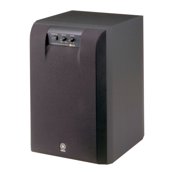
SUPERWOOFER SYSTEM YST-SW45
■ CONTENTS
SPECIFICATIONS
.......................................................... 1
DIMENSIONS
................................................................. 1
........................................................... 2
.............................................................. 2
1 0 0 6 7 6
POWERED SUBWOOFER SYSTEM
YST-SW45
VOLUME
150Hz
0
10
.......................................... 1
................................... 3
SERVICE MANUAL
IMPORTANT NOTICE
This manual has been provided for the use of authorized YAMAHA
Retailers and their service personnel.
It has been assumed that basic service procedures inherent to the
industry, and more specifically YAMAHA Products, are already
known and understood by the users, and have therefore not been
restated.
WARNING:
Failure to follow appropriate service and safety
procedures when servicing this product may result
in personal injury, destruction of expensive
components, and failure of the product to perform
as specified. For these reasons, we advise all
YAMAHA product owners that any service
required should be performed by an authorized
YAMAHA Retailer or the appointed service
representative.
IMPORTANT:
The presentation or sale of this manual to any
individual or firm does not constitute authorization,
certification or recognition of any applicable
technical capabilities, or establish a principle-agent
relationship of any form.
The data provided is believed to be accurate and applicable to the
unit(s) indicated on the cover. The research, engineering, and service
departments of YAMAHA are continually striving to improve
YAMAHA products. Modifications are, therefore, inevitable and
specifications are subject to change without notice or obligation to
retrofit. Should any discrepancy appear to exist, please contact the
distributor's Service Division.
WARNING:
S t a t i c d i s c h a r g e s c a n d e s t r o y e x p e n s i v e
components. Discharge any static electricity your
body may have accumulated by grounding yourself
to the ground buss in the unit (heavy gauge black
wires connect to this buss).
IMPORTANT:
Turn the unit OFF during disassembly and part
replacement. Recheck all work before you apply
power to the unit.
......................................................... 4
....................................................................... 4
................................................ 8
............................................................. 9~15
...................................... 5~7
P.O.Box 1, Hamamatsu, Japan
Advertisement
Table of Contents

Related Manuals for Yamaha YST-SW45


Summary of Contents for Yamaha YST-SW45
-
Page 1: Table Of Contents
YST-SW45 SERVICE MANUAL IMPORTANT NOTICE This manual has been provided for the use of authorized YAMAHA Retailers and their service personnel. It has been assumed that basic service procedures inherent to the industry, and more specifically YAMAHA Products, are already known and understood by the users, and have therefore not been restated. -
Page 2: To Service Personnel
YST-SW45 AC LEAKAGE ■ TO SERVICE PERSONNEL WALL EQUIPMENT TESTER OR OUTLET UNDER TEST EQUIVALENT Critical Components Information. Components having special characteristics are marked and must be replaced with parts having specifications equal to those originally installed. INSULATING TABLE WARNING: CHEMICAL CONTENT NOTICE! The solder used in the production of this product contains LEAD. -
Page 3: Internal View
YST-SW45 ■ INTERNAL VIEW 1 MAIN P.C.B. (4) 2 MAIN P.C.B. (3) 3 MAIN P.C.B. (1) 4 MAIN P.C.B. (2) 5 Power Transformer Right side internal view ■ REAR PANELS U, C models R model A model OUTPUT AUTO OUTPUT... -
Page 4: Disassembly Procedures
YST-SW45 ■ DISASSEMBLY PROCEDURES (Remove parts in the order as numbered.) 1. Removal of Front Grille 2. Remove of Speaker The front grille is fixed to the cabinet with dowels at 4 a. Remove 4 screws (1) in Fig. 2, and remove the locations. -
Page 5: Block Diagram
YST-SW45 ■ BLOCK DIAGRAM VOLUME IC1A IC1B L.P.F IC7A 6dB/oct IC7B SPEAKER INPUT 1 L.P.F 6dB/oct L.P.F H.P.F L.P.F 12dB/oct 12dB/oct 6dB/oct POWER A.N.I.C IC2,3,6 HIGH LIMITER Q3, 6 D4,D5 OUTPUT PROTECTION Q1,D2 POWER POWER SW REGULATOR SUPPLY TIMER Q2,D3... -
Page 6: Printed Circuit Board
YST-SW45 ■ PRINTED CIRCUIT BOARD (Foil side) MAIN P.C.B. (1) From: MAIN (7) From: MAIN (2) – SPEAKER – From: MAIN (4) From: MAIN (3) - Page 7 YST-SW45 ■ PRINTED CIRCUIT BOARD (Foil side) To: MAIN (3) To: VOLTAGE MAIN P.C.B. (2) SELECTOR To: MAIN (1) (GENERAL model) MAIN (6) From: MAIN (5) MAIN P.C.B. (3) From: MAIN (2) To: MAIN (1) AUTO INPUT2 STANDBY OUTPUT / INPUT...
- Page 8 YST-SW45 ■ PRINTED CIRCUIT BOARD (Foil side) MAIN P.C.B. (4) To: MAIN (1) MAIN P.C.B. (5) POWER To: MAIN (2) MAIN P.C.B. (6) MAIN P.C.B. (7) To: MAIN (1) From: MAIN (2) POWER TRANSFORMER From: VOLTAGE SELECTOR (GENERAL model)
-
Page 9: Schematic Diagram
YST-SW45 SCHEMATIC DIAGRAM 14.4 35.9 36.7 -0.4 -0.4 -1.3 -36.8 -34.5 -1.3 -35.7 14.2 14.4 -14.2 14.4 14.4 -1.8 AC57.4 -36.8 36.7 -14.2 25.4 14.4 -14.2 32.5 14.4 -14.2 14.9 -14.7 -32.7 -14.2 12.7 14.2 12.7 AC12.2 -13.9 12.7 PIN CONNECTION DIAGRAM OF TRANSISTORS, DIODES AND ICS. -
Page 10: Parts List
YST-SW45 ■ WARNING PARTS LIST Components having special characteristics are marked s and must be replaced with parts having specifications equal to those originally in- stalled. ■ ELECTRICAL PARTS Carbon resistors (1/6W or 1/4W) are not included in the ELECTRICAL ●... - Page 11 YST-SW45 Schm Schm Ref. PART NO. Description Ref. PART NO. Description V3359100 P.C.B. MAIN(UC) VH620500 C.EL 10uF 25V(RT) V3359200 P.C.B. MAIN(RT) VJ836900 C.EL 10uF V3359300 P.C.B. MAIN(A) FG214100 C.CE 0.01uF V3359400 P.C.B. MAIN(BG) FG213100 C.CE 1000pF CB1 LB932020 CN.BS.PIN VJ839100 C.EL CB2 VD004800 CN.BS.PIN...
- Page 12 YST-SW45 Schm Schm Ref. PART NO. Description Ref. PART NO. Description VC407900 TR 2SD1913 R,S BB070700 GND.MTL VC614000 TR 2SB1274 Q,R,S VN774800 GND.WSHR MEP1866 #11102 iC1815M0 TR 2SC1815 Y,GR V3619700 CN.ASSY 8P 500mm iC1815M0 TR 2SC1815 Y,GR V3619600 CABLE.ASSY 2P 450mm...
- Page 13 YST-SW45 ■ EXPLODED VIEW R,T models 5-31 5-26 5-26 5-27 5-10 5-10 5-31 5-26 5-20 5-29 5-22 5-18 5-26 5-14 5-13 5-15 5-30 5-12 5-11 5-24 5-19 5-25 5-28 5-28 4-15 5-17 5-16 4-11 4-12 5-17 5-16...
Need help?
Do you have a question about the YST-SW45 and is the answer not in the manual?
Questions and answers