Yamaha YST-SW1500 Service Manual
Hide thumbs
Also See for YST-SW1500:
- Owner's manual (24 pages) ,
- Product catalog (44 pages) ,
- Owner's manual (143 pages)
Table of Contents
Advertisement
YST-SW1500
This manual has been provided for the use of authorized YAMAHA Retailers and their service personnel.
It has been assumed that basic service procedures inherent to the industry, and more specifically YAMAHA Products, are already known and understood by the users,
and have therefore not been restated.
WARNING:
Failure to follow appropriate service and safety procedures when servicing this product may result in personal injury, destruction of expensive
components, and failure of the product to perform as specified. For these reasons, we advise all YAMAHA product owners that any service required
should be performed by an authorized YAMAHA Retailer or the appointed service representative.
IMPORTANT:
The presentation or sale of this manual to any individual or firm does not constitute authorization, certification or recognition of any applicable
technical capabilities, or establish a principle-agent relationship of any form.
The data provided is believed to be accurate and applicable to the unit(s) indicated on the cover. The research, engineering, and service departments of YAMAHA are
continually striving to improve YAMAHA products. Modifications are, therefore, inevitable and specifications are subject to change without notice or obligation to
retrofit. Should any discrepancy appear to exist, please contact the distributor's Service Division.
WARNING:
Static discharges can destroy expensive components. Discharge any static electricity your body may have accumulated by grounding yourself to the
ground buss in the unit (heavy gauge black wires connect to this buss).
IMPORTANT:
Turn the unit OFF during disassembly and part replacement. Recheck all work before you apply power to the unit.
I CONTENTS
TO SERVICE PERSONNEL .......................................... 2
FRONT PANEL .............................................................. 2
REAR PANELS .......................................................... 3~4
DISASSEMBLY PROCEDURES / 分解手順 ............. 6~7
SERVICE POSITION ...................................................... 7
REPAIR PROCEDURES / 修理手順 ........................ 8~11
ADJUSTMENT / 調整 ............................................. 12~14
1 0 0 8 2 8
SUBWOOFER SYSTEM
V983440
IMPORTANT NOTICE
SERVICE MANUAL
IC DATA ....................................................................... 15
BLOCK DIAGRAM ....................................................... 16
PRINTED CIRCUIT BOARD .................................. 17~21
IC BLOCK ..................................................................... 22
PIN CONNECTION DIAGRAM ................................... 22
SCHEMATIC DIAGRAM .............................................. 23
PARTS LIST ........................................................... 25~37
REMOTE CONTROL .................................................... 38
Parts List for Carbon Resistors ................................ 39
P.O.Box 1, Hamamatsu, Japan
Advertisement
Table of Contents

Related Manuals for Yamaha YST-SW1500


Summary of Contents for Yamaha YST-SW1500
-
Page 1: Table Of Contents
The data provided is believed to be accurate and applicable to the unit(s) indicated on the cover. The research, engineering, and service departments of YAMAHA are continually striving to improve YAMAHA products. Modifications are, therefore, inevitable and specifications are subject to change without notice or obligation to retrofit. -
Page 2: To Service Personnel
YST-SW1500 I TO SERVICE PERSONNEL AC LEAKAGE WALL EQUIPMENT TESTER OR 1. Critical Components Information OUTLET UNDER TEST EQUIVALENT Components having special characteristics are marked s and must be replaced with parts having specifications equal to those originally installed. 2. Leakage Current Measurement (For 120V Models Only) - Page 3 YST-SW1500 I REAR PANELS U, C models A model B model...
- Page 4 YST-SW1500 G model K model J model...
-
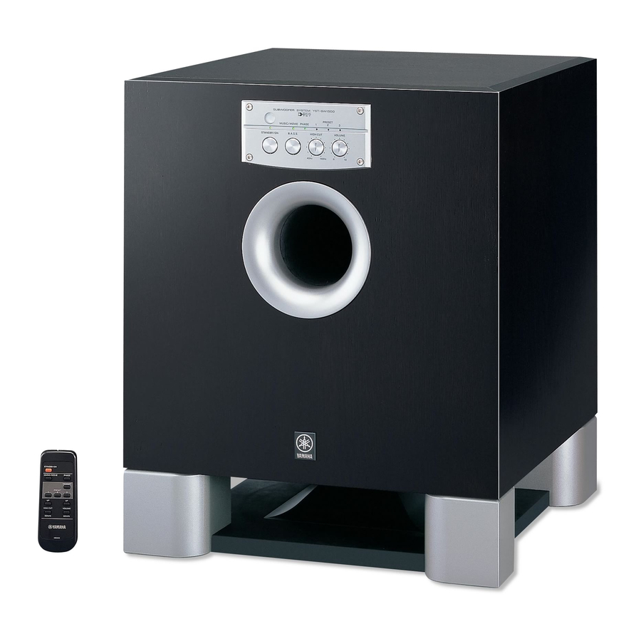
Page 5: Front Panel
YST-SW1500 I SPECIFICATIONS / 参考仕様 Type / 型式 ....Advanced Yamaha Active Servo Technology Power Supply / 電源 U, C models ............AC 120 V, 60 Hz Output Power / 出力 ....1kW (100 Hz, 5 ohms 10% T.H.D.) A model ............... AC 240 V, 50 Hz Input Sensitivity / 入力感度... -
Page 6: Disassembly Procedures / 分解手順
YST-SW1500 I DISASSEMBLY PROCEDURE / 分解手順 (Remove parts in the order as numbered.) (番号順に部品を取り外してください。) AC電源コンセントから、電源コードを抜いてください。 Disconnect the power cable from the AC outlet. 1. Removal of Front Panel Ass'y 1. フロントパネルAss'yの外し方 a. Remove 4 screws (1) and then remove the Front Panel a. -
Page 7: Service Position
YST-SW1500 3. Removal of Driver 3. スピーカーユニットの外し方 a. Remove 8 screws (3) and then remove the Base a. ③のネジ8本を外し、ベースAss'yを取り外します。 Ass'y. (Fig. 3) (Fig. 3) b. Remove 8 screws (4) and then remove the Driver. b. ④のネジ8本を外し、スピーカーユニットを取り外しま (Fig. 3) す。 (Fig. 3)... -
Page 8: Repair Procedures / 修理手順
YST-SW1500 I REPAIR PROCEDURES / 修理手順 When the power amplifier has failed, it is possible that the パワーアンプ部が故障した場合、SW電源部も故障してい る可能性がありますので、パワーアンプ部とSW電源部を switching power supply section has also failed. Therefore, 切り離して修理することを推奨します。 it is recommended to separate the power amplifier section and the switching power supply section for the repair work. - Page 9 YST-SW1500 Oscilloscope オシロスコープ MAIN (1) P.C.B. Q22A Q39C Q28A Q33A R170 Ground side of probe プローブのグラウンド側 Q28C Q33C Q22C Q39A JY202 JY201 100uF 5.6kΩ − + GND OUT Signal Generator 信号発生器 − + Stabilized DC Power Source 直流安定化電源 Set to -30.
- Page 10 YST-SW1500 3. Repairing switching power supply 3. SW電源部 (POWER (1) P.C.B.) の修理 section (POWER (1) P.C.B.) 危険回避 C102、C103には電源OFF後も高電圧が維持されるため To avoid possible danger: 危険です。 C102 and C103 are dangerous, for a high voltage is 修理前に100Ω 5W程度の抵抗をコンデンサの端子間に retained there even after the power is turned off.
- Page 11 YST-SW1500 Oscilloscope オシロスコープ POWER (1) P.C.B. Caution: Use the AC range. 注意:ACレンジを使用します。 Ground side of probe プローブのグラウンド側 C103 C102 Fig. B...
- Page 12 SW1500 のボリュームを調整します。 2) Turn on the power to YST-SW1500. 3) Adjust the output level of the signal generator and the 波形観測 volume of YST-SW1500 so that the output level 上記の設定において、CH1 で観測される波形により判断し observed at oscilloscope CH2 is 70Vp-p. ます。 Waveform observation With the settings made as described above, observe the waveform obtained at CH1 for judgment.
-
Page 13: Adjustment
YST-SW1500 •Idling Adjustment ●アイドリング調整 To stabilize operation of the amplifier, turn ON the power 無負荷、無信号状態で電源投入後1 ∼2 分間エージング with no input signal and wait for 1 or 2 minutes in non を行ってください。 loaded condition before the adjustment. テストポイント 調整箇所 規格 (DC)... - Page 14 YST-SW1500 • AUTO STANDBY operation check ●AUTO STANDBY動作確認 Setting 設定 1) Turn off the POWER switch. 1) 主電源スイッチをOFFにします。 2) Set the AUTO STANDBY/sensing switch to OFF. 2) オートスタンバイ/感度スイッチを 「切」 に設定します。 3) Connect the output of the signal generator to the L/ 3)...
-
Page 15: Ic Data
YST-SW1500 I IC DATA IC12 : LC651152N (POWER P.C.B.) µ-COM PG0/AD4 PA3/AD3 PA0/AD0 PG1/AD5 PA2/AD2 Port A PA3/AD3 PG2/AD6 PA1/AD1 PG3/AD7 PA0/AD0 STACK 1 8 bit PE1/WDR STACK 8 I. DEC PG0/AD4 Port G OSC1 PG3/AD7 System Bus OSC2 Port C... -
Page 16: Block Diagram
YST-SW1500 I BLOCK DIAGRAM... - Page 17 YST-SW1500 • Semiconductor Location I PRINTED CIRCUIT BOARD (Foil side) Ref. No. Location Ref. No. Location POWER (1) POWER (1) MAIN (1) P. C. B. (Lead Type Device) POWER POWER Q22A Q22C BASS Q28A Q28C MUTE Q33A Q33C MAIN Q39A...
- Page 18 YST-SW1500 • Semiconductor Location I PRINTED CIRCUIT BOARD (Foil side) Ref. No. Location IC11 MUTE MAIN (1) IC19 IC24 CSTO CSTI MAIN (2) P. C. B. (Lead Type Device) POWER (2) HCUT Circuit No. U, C C1, 139, 140 C118, 119...
- Page 19 YST-SW1500 I PRINTED CIRCUIT BOARD (Foil side) POWER (1) P. C. B. (Lead Type Device) MAIN (1) MAIN (1) POWER (4) INLET C139 MAIN (1) Circuit No. U, C C1, 139, 140 C118, 119 • Semiconductor Location CB11 CB14 Ref. No. Location Ref.
- Page 20 YST-SW1500 I PRINTED CIRCUIT BOARD (Foil side) POWER (2) P. C. B. (Lead Type Device) POWER (2) P. C. B. (Lead Type Device) MAIN (2) MAIN (2) C Version D Version • Semiconductor Location Ref. No. Location IC12 IC13 IC16...
- Page 21 YST-SW1500 • Semiconductor Location I PRINTED CIRCUIT BOARD (Foil side) Ref. No. Location POWER (3) P. C. B. (Lead Type Device) (Lead Type Device) INLET P. C. B. POWER (2) POWER (1) PHASE MUSIC/ STANDBY/ MOVIE PRESET AC IN POWER (4) P. C. B.
-
Page 22: Ic Block
YST-SW1500 I IC BLOCK IC1, 2, 4, 6, 22, 23: µPC4570HA IC7: NJM78L08A IC9: IR2110 IC13, 16: LB1641 Dual OP-Amp Voltage Regulator High and Low Side Driver Motor Driver DETECT LEVEL SHIFT PULSE FILTER VDD/VCC VOUT LEVEL PULSE Vcc Vo... -
Page 23: Schematic Diagram
YST-SW1500 SCHEMATIC DIAGRAM Point 1 D55 and D54 PRE DRIVE POWER DRIVE L.P.F. 118.0 118.1 118.1 117.6 117.4 118.0 117.6 A D55 118.0 118.1 11.7 117.6 -11.9 117.3 117.4 118.1 116.8 117.6 116.8 116.8 B D54 -11.8 118.1 11.7 POWER ON... -
Page 24: Parts List
YST-SW1500 PARTS LIST I ELECTRICAL PARTS I WARNING Components having special characteristics are marked s and must be replaced with parts having specifications equal to those originally installed. Carbon resistors (1/6W or 1/4W) are not included in the ELECTRICAL PARTS List. For the parts No. of the carbon resistors, refer to last page. - Page 25 YST-SW1500 P.C.B. MAIN Schm Ref. PART NO. Description Remarks Markets 部 品 名 Rank V9860000 P.C.B. MAIN PCB メイン V9860200 P.C.B. MAIN PCB メイン V9860300 P.C.B. MAIN PCB メイン VB390200 CN.BS.PIN コネクタベースポスト 01 VB390100 CN.BS.PIN ベースピン VB390700 CN.BS.PIN コネクタベースポスト 01 LB932040 CN.BS.PIN ベースポスト LB932030 CN.BS.PIN ベースポスト...
- Page 26 YST-SW1500 P.C.B. MAIN Schm Ref. PART NO. Description Remarks Markets 部 品 名 Rank V3091400 C.EL 47uF 160V ケミコン UR797470 C.EL 47uF 100V ケミコン UR797470 C.EL 47uF 100V ケミコン UA655100 C.MYLAR 0.1uF マイラーコン V8584600 C.PP 220pF 630V PPコン V8584600 C.PP 220pF 630V PPコン...
- Page 27 YST-SW1500 P.C.B. MAIN Schm Ref. PART NO. Description Remarks Markets 部 品 名 Rank VU264100 DIODE 1SR139-400 ダイオード VU264100 DIODE 1SR139-400 ダイオード VU264100 DIODE 1SR139-400 ダイオード VU264100 DIODE 1SR139-400 ダイオード VU264100 DIODE 1SR139-400 ダイオード VU264100 DIODE 1SR139-400 ダイオード VU264100 DIODE 1SR139-400 ダイオード...
- Page 28 YST-SW1500 P.C.B. MAIN Schm Ref. PART NO. Description Remarks Markets 部 品 名 Rank iA097030 TR 2SA970 GR,BL トランジスタ iA097030 TR 2SA970 GR,BL トランジスタ iC287820 TR 2SC2878 A,B トランジスタ iC224030 TR 2SC2240 GR,BL トランジスタ iC287820 TR 2SC2878 A,B トランジスタ iA097030 TR 2SA970 GR,BL トランジスタ...
- Page 29 YST-SW1500 P.C.B. MAIN Schm Ref. PART NO. Description Remarks Markets 部 品 名 Rank HV755220 R.CAR.FP 220Ω 1/4W 不燃化カーボン抵抗 HB026220 R.MTL.FLM 2.2KΩ 1/4W 金属被膜抵抗 HV755560 R.CAR.FP 560Ω 1/4W 不燃化カーボン抵抗 HV755820 R.CAR.FP 820Ω 1/4W 不燃化カーボン抵抗 HB027200 R.MTL.FLM 20KΩ 1/4W 金属被膜抵抗 HB027100 R.MTL.FLM 10KΩ...
- Page 30 YST-SW1500 P.C.B. MAIN & P.C.B. POWER Schm Ref. PART NO. Description Remarks Markets 部 品 名 Rank R171 HV755680 R.CAR.FP 680Ω 1/4W 不燃化カーボン抵抗 R172 HV755330 R.CAR.FP 330Ω 1/4W 不燃化カーボン抵抗 R234 V6146800 R.WW 0.22Ω+0.22Ω セメント抵抗 R243 HV755470 R.CAR.FP 470Ω 1/4W 不燃化カーボン抵抗 R244 HV755470 R.CAR.FP 470Ω...
- Page 31 YST-SW1500 P.C.B. POWER Schm Ref. PART NO. Description Remarks Markets 部 品 名 Rank UA655100 C.MYLAR 0.1uF マイラーコン V5877600 C.MYLAR 0.47uF 250V マイラーコン V5900200 C.MYLAR 250V KABG マイラーコン VY675100 C.CE.SAFTY 4700pF 250V KABG 規格認定コン KH VY675100 C.CE.SAFTY 4700pF 250V KABG 規格認定コン KH VY675100 C.CE.SAFTY...
- Page 32 YST-SW1500 P.C.B. POWER P.C.B. POWER & P.C.B. INLET Schm Schm Ref. PART NO. Description Remarks Markets 部 品 名 Rank Ref. PART NO. Description Remarks Markets 部 品 名 Rank VU758600 LED(gr) SLR-342MC LED R211 HV754220 R.CAR.FP 22Ω 1/4W 不燃化カーボン抵抗 VU758600 LED(gr) SLR-342MC LED...
- Page 33 YST-SW1500 I EXPLODED VIEW I MECHANICAL PARTS Schm Ref. PART NO. Description Remarks Markets 部 品 名 Rank V9968600 CABINET ASS'Y キャビネットASSY V9968700 CABINET ASS'Y キャビネットASSY X3483A00 DRIVER, WOOFER 30cm 6Ω JA31280 スピーカーユニット V9970700 PORT ASS'Y ポート ASSY V9975700 LEG ASS'Y レッグASSY V9975800 LEG ASS'Y レッグASSY ...
- Page 34 YST-SW1500 I FRONT PANEL ASS'Y 3-31 3-23 3-32 3-31 3-31 3-17 3-31 5-2 (3) 3-18 3-15 3-11 Schm Ref. PART NO. Description Remarks Markets 部 品 名 Rank V9977200 SW KNOB ASS'Y SWノブASSY 05 V9977300 SW KNOB ASS'Y SWノブASSY 05 V9977400 VR KNOB ASS'Y VRノブASSY ...
- Page 35 YST-SW1500 I REAR PANEL ASS'Y 5-54 5-32 5-11 5-53 5-54 5-15 5-31 5-51 5-16 5-19 5-34 5-55 5-32 5-1 (2) 5-57 5-35 5-51 5-20 5-56 5-2 (1) 5-51 Parts Side 5-33 5-51 5-21 5-51 5-51 5-23 5-33 5-22 5-35 5-52...
- Page 36 YST-SW1500 I REAR PANEL ASS'Y Schm Ref. PART NO. Description Remarks Markets 部 品 名 Rank V9860000 P.C.B. ASS'Y MAIN PCB メイン V9860200 P.C.B. ASS'Y MAIN PCB メイン V9860300 P.C.B. ASS'Y MAIN PCB メイン V9888000 P.C.B. ASS'Y POWER PCB集成 パワー V9888100 P.C.B. ASS'Y POWER PCB集成 パワー V9888200 P.C.B.
-
Page 37: Remote Control
YST-SW1500 I REMOTE CONTROL 2Ω SID303C-01 47µF 27Ω 2SC3265-0 CARR IC1 : M34282M1-715GP 3.0V 0.1µF XOUT 4.00MHz CUSTOM CODE (HEX): 7B Data Code Name (HEX) STANDBY/ON MUSIC/MOVIE HIGH CUT UP HIGH CUT DOWN PHASE MEMORY VOLUME UP VOLUME DOWN V983440... -
Page 38: Parts List For Carbon Resistors
YST-SW1500 Parts List for Carbon Resistors Value 1/4W Type Part No. 1/6W Type Part No. Value 1/4W Type Part No. 1/6W Type Part No. 1.0 Ω 3100 3100 10 kΩ 7100 7100 HJ35 HF85 HF45 HF45 1.8 Ω ❊ 3180 11 kΩ... - Page 39 YST-SW1500...
Need help?
Do you have a question about the YST-SW1500 and is the answer not in the manual?
Questions and answers