Table of Contents
Advertisement
APCD-500
User's manual
M 890-00472 rev.10
Chain Disk controller
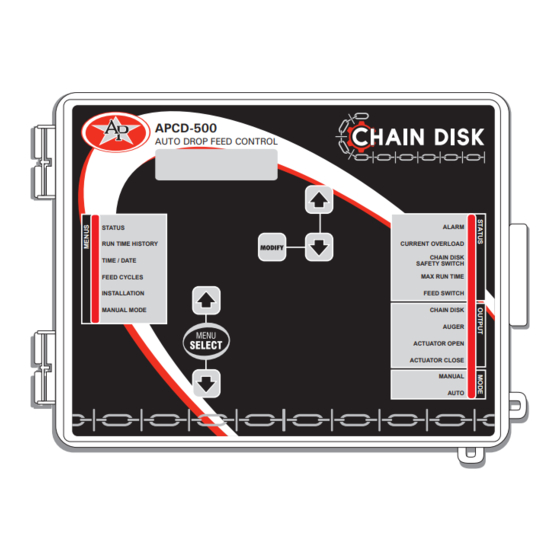
APCD-500
AUTO DROP FEED CONTROL
STATUS
RUN TIME HISTORY
TIME / DATE
FEED CYCLES
INSTALLATION
MANUAL MODE
ALARM
CURRENT OVERLOAD
CHAIN DISK
SAFETY SWITCH
MAX RUN TIME
FEED SWITCH
CHAIN DISK
AUGER
ACTUATOR OPEN
ACTUATOR CLOSE
MANUAL
AUTO
REV14.
Advertisement
Table of Contents

Related Manuals for GSi Chain Disk APCD-500


Summary of Contents for GSi Chain Disk APCD-500
- Page 1 APCD-500 Chain Disk controller User’s manual APCD-500 AUTO DROP FEED CONTROL STATUS ALARM CURRENT OVERLOAD RUN TIME HISTORY CHAIN DISK TIME / DATE SAFETY SWITCH FEED CYCLES MAX RUN TIME FEED SWITCH INSTALLATION CHAIN DISK MANUAL MODE AUGER ACTUATOR OPEN ACTUATOR CLOSE MANUAL AUTO...
- Page 2 APCD-500 Manufacturer GSI Electronics 5200, Armand-Frappier St-Hubert (Qc) Canada J3Z 1G5 WARNINGS The warranty can be void if this product is used in a manner not specified by the manufacturer. Every effort has been made to ensure that this manual is complete, accurate and up-to-date.
-
Page 3: Table Of Contents
APCD-500 TABLE OF CONTENTS INTRODUCTION ..............5 1.1. Precautions ................5 1.2. Symbols of the Manual ............5 USER INTERFACE ..............6 2.1. Location of the Controls ............6 2.2. Adjusting a Parameter ............7 MOUNTING INSTRUCTIONS ............7 3.1. Mounting the Controller on the Wall ......... 7 3.2. - Page 4 APCD-500 5.5. Run Time Settings ..............32 5.6. Installation Setup ..............32 5.7. Manual & Test Modes ............37 5.7.1. Manual Filling of the Chain Disk Systems ......37 5.7.2. Manual Start / Stop ............37 5.7.3. Bypassing a Chain Disk System ..........38 5.7.4.
-
Page 5: Introduction
APCD-500 INTRODUCTION 1.2. Symbols of the Manual 1.1. Precautions Warning. Read the following text carefully; it contains important information which, if ignored, may WARNING: Read and save these cause the controller to operate instructions! improperly. Safety may be jeopardized if the equipment High Voltage. -
Page 6: User Interface
APCD-500 USER INTERFACE Function LED — This pilot light shows what function is selected on the main menu. 2.1. Location of the Menu Select Buttons — These buttons are Controls used to select a function from the main menu. LCD Display — The LCD display on the left gives the current readings and parameters APCD-500 AUTO DROP FEED CONTROL... -
Page 7: Adjusting A Parameter
APCD-500 2.2. Adjusting a Parameter • Do not install rigid conduit into electrical knockouts. Only nylon cable glands are per- Use the arrow keys to select the parameter mitted for cable or wire fastening. that needs to be adjusted. When it is selected, • The controller has no power-on switch. -
Page 8: Controller Overview
APCD-500 CONTROLLER OVERVIEW 4.1. Features • Timed or continuous feed cycles; The APCD-500 controls the feed entry into • With or without proximity sensors. Chain Disk Systems and the distribution of • With or without actuators / air valves to feed to the animals. -
Page 9: Independent Chain Disk Systems With A Common Auger
APCD-500 4.2.2. Independent Chain Disk Refer to section 4.4.3 & 4.4.4 to get information about the filling process Systems with a Common Auger in this Chain Disk System setup. Independent Chain Disk Systems that share a common bin auger are filled following the nu- merical order: the master Chain Disk System is filled first, followed by Slave System #1, Slave System #2, etc. -
Page 10: Feed Distribution Modes
APCD-500 4.3. Feed Distribution Modes 4.3.2. Continuous Feed Distribution The continuous feed distribution mode 4.3.1. Timed Feed Distribution ensures the system is always full: the bin auger starts bringing feed into the Chain When feed is distributed according to a timer, Disk System as soon as it gets empty. -
Page 11: Filling Process
APCD-500 4.4. Filling Process Continuous Mode — Proximity sensor on the Chain Disk Operation of the Bin Auger: System Line after the Last Drop At the start-up of each feeding cycle, right If the proximity sensor is located on the Chain after the Auger’s Delay has elapsed, the bin Disk System line after the last drop, the system auger starts bringing feed into the Chain Disk... - Page 12 APCD-500 Filling Process According to the Refer to section 5.6 to set the bin auger parameters System Setup: NOTE: The whole Chain Disk stops The filling process of Chain Disk System de- running when an alarm is active! pends on your particular system setup. Locate your particular application setup on the hierarchy tree below and then refer to the proper section of the manual to get explanations about the filling...
-
Page 13: Filling Cascaded Chain Disk Systems With Continuous Feed Distribution Mode
APCD-500 4.4.1. Filling Cascaded Chain Disk 4. The Farthest Chain Disk System is Full — The controller knows the farthest Chain Systems with Continuous Feed Disk System is full when its proximity sensor Distribution Mode detects feed for 5 seconds without interrup- tion. - Page 14 APCD-500 APCD-500, rev10...
-
Page 15: Filling Cascaded Chain Disk Systems With Timer Mode
APCD-500 4.4.2. Filling Cascaded Chain Disk 5. The Farthest Chain Disk System is Full Systems with Timer Mode • If a proximity sensor is used: the con- troller knows the Chain Disk System is full 1. Beginning the Filling Process — The filling when the proximity sensor detects feed process starts at the start-up of a feed cycle for 5 seconds. - Page 16 APCD-500 APCD-500, rev10...
- Page 17 APCD-500 APCD-500, rev10...
-
Page 18: Filling Independent Chain Disk Systems With A Common Bin Auger Using Continuous Feed Distribution Mode
APCD-500 4.4.3. Filling Independent Chain Disk 4. The Chain Disk System is Full — The controller knows the Chain Disk System is Systems with a Common Bin Auger us- full when the proximity sensor located at its ing Continuous Feed Distribution Mode end detects feed for 5 seconds without inter- ruption. - Page 19 APCD-500 APCD-500, rev10...
-
Page 20: Filling Independent Chain Disk Systems With A Common Bin Auger Using Timer Mode
APCD-500 4.4.4. Filling Independent Chain 4. Filling the First Chain Disk System — When the “Purge Time” is over, all drive units Disk Systems with a Common Bin stop except for the first Chain Disk System Auger using Timer Mode to be filled: the master Chain Disk System. - Page 21 APCD-500 APCD-500, rev10...
- Page 22 APCD-500 APCD-500, rev10...
-
Page 23: Filling Independent Chain Disk Systems With Individual Bin Au- Gers Using Continuous Feed Distribution Mode
APCD-500 4.4.5. Filling Independent Chain 4. A Chain Disk System is Full — The con- troller knows a Chain Disk System is full Disk Systems with Individual Bin Au- when the proximity sensor detects feed for gers Using Continuous Feed Distribu- 5 seconds without interruption. - Page 24 APCD-500 APCD-500, rev10...
-
Page 25: Filling Independent Chain Disk Systems With Individual Bin Au- Gers Using The Timed Feed Distribution Mode
APCD-500 5. The Chain Disk System is Full: 4.4.6. Filling Independent Chain Disk Systems with Individual Bin Au- • If a proximity sensor is used: The controller knows a Chain Disk System gers Using the Timed Feed Distribu- is full when the proximity sensor detects tion Mode feed for 5 seconds. - Page 26 APCD-500 APCD-500, rev10...
- Page 27 APCD-500 APCD-500, rev10...
-
Page 28: Feed Delivery Process
APCD-500 4.5. Feed Delivery Process 4.6. Feed Cycle After the Chain Disk Systems have been When the feed distribution is done in timer filled up, feed is ready to be delivered to mode, the user must specify the moment at the animals. -
Page 29: Parameter Settings
APCD-500 5.2. Run Time History PARAMETER SETTINGS The controller has an history menu in which 5.1. Controller Status the daily run time of the Chain Disk Systems (master and Slave Chain Disk Systems) are The STATUS menu shows the ongoing opera- logged in for the past 5 days. -
Page 30: Time & Date
APCD-500 Note: The notification message re- 5.3. Time & Date peatedly disappears and reappears until the time and date are set. 1. Use the menu select buttons to select the 5.4. Feed Cycle Settings TIME / DATE menu. The current time and date are displayed. - Page 31 APCD-500 Chain Disk System Cycle Worksheet Chain Disk System’s Maximum Run Time Start Full Dump Feed Cycles Time Time Master Slave Slave Slave Slave Slave Slave Slave Chain Chain Chain Chain Chain Chain Chain Chain Disk Disk 1 Disk 2 Disk 3 Disk 4 Disk 5...
-
Page 32: Run Time Settings
APCD-500 5.5. Run Time Settings 5.6. Installation Setup The run time parameter represents the time The following section describes how to that is required to fill-up each Chain Disk customize the controller for your particular System. It ranges from 00:01 hh:mm to application. - Page 33 APCD-500 Common Auger — If independent Slave Chain Continuous Feeding / Timed Feeding — Se- lect “Yes” to use the continuous feeding Disk Systems are enabled above, specify if mode; select “No” to use timed feed distribu- all Chain Disk Systems have their own bin tion (see sec.
- Page 34 APCD-500 case, it is considered empty after a Actuator Open Time — This is the amount user-defined delay (after Continuous time required for the actuator to open the Feeding Delay). dumps. It ranges from 0 to 120 minutes. * This parameter is available if the actuator is enabled above.
- Page 35 APCD-500 Window Size — This parameter is used to Max Run Time — This is the maximum allow- restart a drive unit that was stopped due to an able running time of a Chain Disk System. The over current condition. The drive unit restarts controller sounds an alarm when the continu- when its amperage draw becomes lower than ous run time of a Chain Disk System exceeds...
- Page 36 APCD-500 Feed Purge Time Delay — The “Feed Purge Delay” is the amount of time required for feed lines to get empty when a common auger is used. Note that the “Purge Delay” must be higher than “Auger Delay”. Set this param- eter to the desired value.
-
Page 37: Manual & Test Modes
APCD-500 5.7. Manual & Test Modes 5.7.2. Manual Start / Stop You can choose to start filling a Chain Disk The manual mode allows activating manually System or to stop it manually (as explained the actuators, air valves and drive units. in previous section). -
Page 38: Bypassing A Chain Disk System
APCD-500 5.7.4. Manual Dump 5.7.3. Bypassing a Chain Disk System The actuator/air valve can only be activated manually when no drive unit is running. The If required, the controller can bypass a Chain Manual Mode pilot light flashes while an ac- Disk System (slave or Master Chain Disk tuator or air valve is controlled manually. -
Page 39: Toggle Switch
APCD-500 5.7.6. Test Mode 5.7.5. Toggle Switch A toggle switch can be connected to the main The test mode allows simulating the amper- age draw of all drive units in order to verify board. This switch allows stopping the drive the controller’s performances. -
Page 40: Alarms
APCD-500 5.8. Alarms 5.8.1. Acknowledging an alarm The following table shows the possible alarms 1. Use the menu select buttons to select the conditions. When an alarm occurs, the whole STATUS menu. The current alarm acknowl- Chain Disk system stops operating until the edgment menu is displayed. -
Page 41: Technical Specifications
APCD-500 TECHNICAL SPECIFICATIONS Type ........APCD-500 Main supply fuse F1 ..... F1A, 250V, fast-blow Main supply/frequency ..230V+10% -20%, 12A, 50/60Hz Housing ......Plastic casing Operating temperature ..0 to 40°C Storage temperature ... -15 to 50°C Ambient relative humidity ... Max 95% (non-condensing) Alarm ........ -
Page 42: Transfer Menu
APCD-500 TRANSFER MENU 7.3. Update/Backup with a USB drive 7.1. Communication Speed The USB drive allows upgrading the firmware 1. Simultaneously press and hold the MENU or software of your controller. It can also be SELECT up- and down-arrow keys for 5 sec- used to make a backup of your controller onds to display the transfer menu. - Page 43 APCD-500 3. Update Firmware 1. MemoryCard -> Control Choose 3. Update Firmware and press MODI- Choose 1. MemoryCard -> Control and press FY to download a new firmware file into your MODIFY to load a new configuration file into controller. This process will not affect your your controller.
-
Page 44: Annex 1: Core Card
APCD-500 ANNEX 1: CORE CARD Removing a Core Card: Inserting a Core Card: Before proceeding, switch power off Before proceeding, switch power off at service panel and lock the switch at service panel and lock the switch disconnecting means to prevent disconnecting means to prevent power from being switched acciden- power from being switched acciden-... -
Page 45: Index
APCD-500 INDEX Setup Cascade setup Actuator / Air valve Activation 32 Activation & settings 34 Feeders’ filling process 11, 13–15, 15, 37 Actuator status LED 6 Setup view 8 Current actuator status 29 Independent feeders with 1 auger Dump Activation 32 Manual feed dump 38–39 Feeders’... - Page 46 APCD-500 Feed distribution Continuous mode Parameter adjustment 7 Activation & settings 33 Password Feed delivery process 28 Activation 36 Feeders’ filling process see Feeder setup Change the password 36 Principle of operation 10 Enter a password 32 Settings 33 Pilot lights see also LEDs Timer mode Trouble light 40 Activation 33...
- Page 47 APCD-500 Time Adjusting improper system time 30 Time and date 30 Time format 35 Toggle switch 39 Transfer menu 42 Trouble light 40 Update 42 USB drive 42 Valve see Actuator /Electric V. Version 36 Warnings Check feed cycles 30, 37 APCD-500, rev10...
Need help?
Do you have a question about the Chain Disk APCD-500 and is the answer not in the manual?
Questions and answers