Table of Contents
Advertisement
Quick Links
Advertisement
Table of Contents

Subscribe to Our Youtube Channel
Related Manuals for GSi Smart Climate 310


Summary of Contents for GSi Smart Climate 310
- Page 1 Smart Climate 310 User’s Guide 895-00676 REV. 04 890-00582 REV.03...
- Page 2 FOR CUSTOMER USE Enter the serial number located on the side of the controller below for future reference. Model number: Smart Climate 310 Serial number: _____________________________ Every effort has been made to ensure that this manual is complete, accurate and up-to-date. The information contained in it is however subject to change without notice due to further developments.
-
Page 3: Table Of Contents
Table of Contents PRECAUTIONS ..................7 ................. 7 ONNECTION RECAUTIONS ..............8 ROBE ONNECTION RECAUTIONS ABOUT THE SMART CLIMATE 310 ............9 USER INTERFACE .................. 10 .................. 12 NTERNAL WITCHES INSTALLATION ..................13 ............... 13 OUNTING THE NCLOSURE ..............13... - Page 4 OMPENSATION HUTOFF RH C – : ..........53 OMPENSATION WITH EATING NITS RH C – ........54 OMPENSATION WITH ARIABLE PEED ............55 IEWING THE ELATIVE UMIDITY EVEL ..........55 DJUSTING THE ELATIVE UMIDITY OINT Smart Climate 310 rev. 03...
- Page 5 PENING Viewing the Static Pressure Level ............ 76 Adjusting High and Low Pressure Set Points ........77 Adjusting the Static Pressure Compensation Value ......78 0-10V OUTPUT ..................79 0-10V O ................79 UTPUT ETTINGS Smart Climate 310 rev. 03...
- Page 6 Updating the Firmware ..............92 Saving the Event Buffer ..............93 INSTALLATION REPORT ................ 94 .................. 95 ELAY SSIGNMENT ................. 96 ROBE SSIGNMENT ................... 97 ETUP CORE CARD ..................99 ................99 EMOVING A ................100 NSERTING A Smart Climate 310 rev. 03...
-
Page 7: Precautions
CAUTION: All wiring must be done by an authorized electrician and must comply with applicable codes, laws and regulations. Be sure power is off before doing any wiring to avoid electrical shocks and equipment damage. Smart Climate 310 rev. 03... -
Page 8: Probe Connection Precautions
NOTICE: Do not ground the shielding. NOTE: Solder the cable joint to ensure a proper contact between the two cables. CAUTION: Do not run probe cables next to other power cables. When crossing over other cables, cross at 90°. Smart Climate 310 rev. 03... -
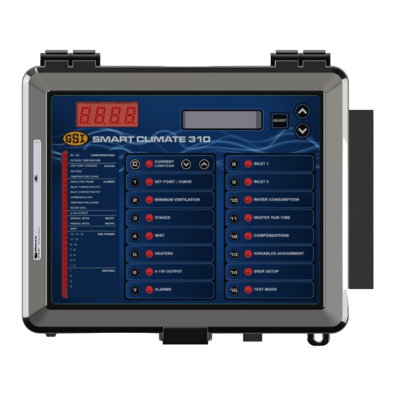
Page 9: About The Smart Climate 310
Climate 310 can control up to 15 fan stages (including 5 stages of variable speed fans), 1 mist stage and/or 4 heating stages. The Smart Climate 310 can also control 2 air inlets and it has 1 built-in 0-10V output to control additional devices such as heaters, fans, chimney dampers or inlets. -
Page 10: User Interface
(see the "Meaning of Status LED" table below for further information). Current condition button — This button gives access to current condition menus. Current condition arrow keys — These buttons give access to the submenus of the Current Condition menu. Smart Climate 310 rev. 03... - Page 11 LED Display — The display on the top left corner of the faceplate shows the current room temperature averaged over all selected room temperature probes. It can also display the static pressure level or the air inlet position. Status LED Meanings Smart Climate 310 rev. 03...
-
Page 12: Internal Switches
Internal Switches Internal switches are located inside the auxiliary module. Smart Climate 310 rev. 03... -
Page 13: Installation
NC (normally closed) terminal for wiring. If the alarm activates when • current is supplied at the input, use the NO (normally open) terminal for wiring. Smart Climate 310 rev. 03... -
Page 14: Choosing The Motor Type
Adjust again to validate. 5. Press the down-arrow key to select the motor curve of the second variable output. 6. Use the arrow keys to adjust the motor curve and then press Adjust again to validate. Smart Climate 310 rev. 03... -
Page 15: Site Monitoring
1. Press Water Consumption. Today's water consumption is displayed. Available if the water counter is enabled in the USER SETUP. 2. Press the down-arrow key to scroll the display. The water consumption of the past 6 days is displayed. Smart Climate 310 rev. 03... -
Page 16: User Setup
5. Press Adjust once again. The seconds flash on the display. Use the arrow keys to adjust the seconds to the desired value. 6. Press Adjust. The month flashes. Use the arrow keys to set the month. Smart Climate 310 rev. 03... -
Page 17: Setting The Parameters
Contrast Set the contrast of the LCD screen to the desired value (from 10 to 100%). Time of Day Format Select the time format. Temperature Units Select the temperature units: Fahrenheit (F°) or Celsius (°C). Smart Climate 310 rev. 03... - Page 18 Select Yes if an outside temperature sensor is connected to the controller. Outside T° Compensation on differentials Select Yes for the controller to adjust the variable stage bandwidth as a function of the outside Accessible if the outside temperature sensor is enabled above. Smart Climate 310 rev. 03...
- Page 19 This switch is located inside the auxiliary module on the Controller Function switch block. Set switch number 6 to the OFF position to use one inlet or switch it to the ON position to use two inlets. Smart Climate 310 rev. 03...
- Page 20 The de-icing function allows activating the 2nd fan stage briefly (i.e., the stage that follows the minimum ventilation stage). This de- icing function prevents fans from freezing in winter. Select Yes to enable this function. Smart Climate 310 rev. 03...
- Page 21 When the room temperature gets too low, the controller can lower the minimum speed of a chosen variable fan stage, disable the fan stage that follows and close the air inlet a little further. Select Yes to use these override functions. Smart Climate 310 rev. 03...
- Page 22 Current Condition, Set Point/Curve and Minimum Speed/Curve. User Setup and Test Mode menus are always password protected, whether this option is enabled or not. Program Version Number The version number of the controller is displayed. Smart Climate 310 rev. 03...
-
Page 23: Automatic Relay Assignment
On/off fan stage does not correspond to stage 1 but to the stage number that follows the last variable fan stage. For example, if fan stage 2 is used for minimum ventilation, the first on/off fan stage is fan stage 3 and it uses relay 1. Smart Climate 310 rev. 03... -
Page 24: Assigning Variable-Speed Outputs
3. Press Adjust once again to validate and step to the next variable output. 4. Press the down-arrow key to select the following fan stage. 5. Repeat steps 1 to 4 to set the status of all variable outputs for each variable-speed fan stage. Smart Climate 310 rev. 03... -
Page 25: Temperature Settings
Today's maximum temperature is displayed along with the time and date. 4. Keep pressing on the navigation down arrow key to look at the minimum and maximum temperature readings that have been recorded each day for the past 6 days. Smart Climate 310 rev. 03... -
Page 26: Viewing Probe Temperatures
4. Press on the navigation down-arrow key once again. Today's maximum outside temperature is displayed, along with the time and date. 5. Keep pressing the navigation down-arrow key to display the minimum and maximum outside temperatures of the past six days. Smart Climate 310 rev. 03... -
Page 27: Temperature Set Points
The controller then changes the temperature set point every hour in a linear fashion between consecutive points of the curve. When the last point of the curve is reached, the temperature set point for that day is maintained until the curve is reactivated. Smart Climate 310 rev. 03... -
Page 28: Specifying The Curve
4. Use the arrow keys to enable or to disable the curve. 5. Press ADJUST once again to validate. NOTE: The controller automatically sets the day number back to -5 days when the user activates the temperature curve. Smart Climate 310 rev. 03... -
Page 29: Setting The Day Value
Accessible if the set point curve is enabled in the USER SETUP. 3. Press Adjust. The current day flashes on the display. 4. Use the up and down arrow keys to set it to the proper value. Smart Climate 310 rev. 03... -
Page 30: Ventilation Control
Consequently, the start temperature of all subsequent fan stages are shifted forward. Smart Climate 310 rev. 03... - Page 31 2 takes the value of the temperature set point and the start temperature of all stages are adjusted consequently (note that if stage 2 is used to ensure minimum ventilation, stage 1 will never be performed). Smart Climate 310 rev. 03...
-
Page 32: Low T° Override Functions
5. If the minimum ventilation stage uses another variable output, press the down arrow key to select it. 6. Repeat steps 1 to 5 to set the minimum ventilation speed of all variable outputs that are used in minimum ventilation. Smart Climate 310 rev. 03... -
Page 33: Adjusting The Minimum Ventilation Timer
3. Press Adjust. The On time starts flashing. 4. Use the arrow keys to set it to the desired value. 5. Press Adjust again, the Off time flashes. 6. Use the arrow keys to set it to the desired value. Smart Climate 310 rev. 03... -
Page 34: Fan Stages
(15) minus the number of activated mist and heating outputs. You can also specify the maximum number of fan stages to be performed and change this number as your ventilation needs are changing. Smart Climate 310 rev. 03... -
Page 35: Variable Speed Stages
If the following stage does not use variable output 1, the output simply stops when this new stage starts; if it uses it, the output returns to minimum speed at the startup of the new stage. Smart Climate 310 rev. 03... - Page 36 When the start temperature of Stage S+1 is reached, variable output 1 goes back to its minimum speed. It then uses the bandwidth of the fan stage S+1 to increase in speed as the room temperature rises. Smart Climate 310 rev. 03...
-
Page 37: Outside Temperature Compensation
If this outside temperature compensation function is enabled in the User setup menu, you must specify a different bandwidth for winter and summer. Normally, the winter’s bandwidth should be greater than the summer’s bandwidth. Smart Climate 310 rev. 03... -
Page 38: Selecting The Maximum Fan Stage
To select the maximum fan stage, proceed as follows: 1. Press Stages. 2. Press Adjust then use the arrow keys to select the desired maximum fan stage. 3. Press Adjust once again to validate. Smart Climate 310 rev. 03... -
Page 39: Adjusting The Starting Temperature For Fan Stages
3. Press Adjust and then use the arrow keys to set the start temperature to the desired value. 4. Press Adjust once again to validate. 5. Repeat steps 1 to 4 to set the start temperature of all fan stages. Smart Climate 310 rev. 03... -
Page 40: Setting The Bandwidth
1 variable fan stage (if applicable). 5. Press Adjust and then use the arrow keys to set winter's bandwidth to the desired value. 6. Repeat steps 1 to 5 to set additional bandwidths. Smart Climate 310 rev. 03... -
Page 41: Adjusting The Minimum Speed Of Variable Outputs
4. Press the down-arrow key to select the second variable output (if applicable). 5. Repeat steps 1 to 4 to set the speed of each variable output for all variable fan stages. Smart Climate 310 rev. 03... -
Page 42: Displaying The Fan Speed
2. Press the current condition's down arrow key to display the speed of the first variable output. Accessible if a variable-speed output is enabled in the User Setup menu. 3. Press the down-arrow key to display the speed of all variable outputs in use. Smart Climate 310 rev. 03... -
Page 43: 0-10V Fan Outputs
At the start temperature: The output operates continuously at its minimum speed, and starts increasing in speed as the temperature rises; At the maximum temperature: The output reaches its maximum intensity; Above the stop temperature: The output is deactivated. Smart Climate 310 rev. 03... -
Page 44: Adjusting The Starting Temperature For 0-10V Outputs
3. Press Adjust then use the arrow keys to set the minimum speed to the desired value. 4. Press Adjust once again, the maximum speed flashes on the display. Use the arrow keys to set it to the desired value. Smart Climate 310 rev. 03... -
Page 45: Selecting Maximum & Stop Temperatures For The 0-10V Fan Output
3. Press Adjust then use the arrow keys to set the maximum temperature to the desired value. 4. Press Adjust once again, the stop temperature flashes on the display. Use the arrow keys to set it to the desired value. Smart Climate 310 rev. 03... -
Page 46: Setting The 0-10V Fan Output's Timer
3. Select which sensors are used to control the 0-10V output. NOTE: Blinking digits represent probes that are assigned for this purpose. NOTE: At least one temperature probe must be selected. 4. Press Adjust then set each probe's status with the arrow keys. Smart Climate 310 rev. 03... -
Page 47: De-Icing The Fans
The de-icing outside temperature ranges from -40 to 120°F (-40.0 to 48.9°C). Only accessible if the de-icing function and outside temperature sensor are activated. 1. Press Minimum Ventilation. 2. Press the down arrow key to select and adjust the outside de-icing temperature. Smart Climate 310 rev. 03... -
Page 48: Setting The De-Icing Cycle
It must thus be longer than the run time. Only accessible if the de-icing function is activated. 1. Press Minimum Ventilation. 2. Press the down arrow key to select and adjust the de-icing On time and cycle. Smart Climate 310 rev. 03... -
Page 49: Mist Cooling
If humidity compensation is used, the controller can disable all mist units when the humidity level is too high. Refer to the Humidity Compensation chapter for further information on this feature. Smart Climate 310 rev. 03... -
Page 50: Setting Start And Stop Temperatures For Timers
6. Press Adjust again to validate. 7. Press the down-arrow key twice. The start temperature of the second mist timer is displayed. 8. Repeat steps 1 to 7 to set the start and stop temperatures of the second mist timer. Smart Climate 310 rev. 03... -
Page 51: Setting Timer 1 & 2 Time On And Time Off
10. Use the arrow keys to set it to the desired value. 11. Press Adjust. The off time of the second mist timer flashes on the display. 12. Use the arrow keys to it to the desired value. 13. Press Adjust to validate the value. Smart Climate 310 rev. 03... -
Page 52: Limiting Mist Shutoff
2. Press the down-arrow key in order to display the Mist Shutoff parameter. 3. Press Adjust. The shutoff limit flashes on screen. Set it to the desired value with the adjustment buttons. Mist shutoff at 95% Smart Climate 310 rev. 03... -
Page 53: Relative Humidity (Rh) Compensation
Heaters can operate in timer mode to reduce the humidity level. When they are used this way, heaters start running in timer mode when the humidity level exceeds the relative humidity set point (refer to the User Setup menu to enable this RH compensation method). Smart Climate 310 rev. 03... -
Page 54: Rh Compensation - With Variable Speed Fans
Smart Climate 310 rev. 03... -
Page 55: Viewing The Relative Humidity Level
2. Press Adjust. The humidity set point flashes on the display. 3. Use the arrow keys to set it to the desired value. 4. Press Adjust to validate. Accessible if the RH compensation function is enabled in the USER SETUP. Smart Climate 310 rev. 03... -
Page 56: Adjusting The Minimum Speed Compensation
Accessible if the RH Compensation function is set to "Min Speed" in the USER SETUP. 3. Press Adjust. The speed compensation flashes on the display. 4. Use the arrow keys to set it to the desired value. 5. Press Adjust to validate the new value. Smart Climate 310 rev. 03... -
Page 57: Heating Timer ( For Rh Compensation )
4. Use the arrow keys to adjust it to the desired value. 5. Press Adjust. The Off timer flashes on the display. 6. Use the arrow keys to adjust it to the desired value. 7. Press Adjust once again to validate. Smart Climate 310 rev. 03... -
Page 58: Heater Settings
HEATER SETTINGS Regular Heating Stages The Smart Climate 310 can control up to 4 heating stages. A heating stage starts when the room temperature decreases to its start temperature. The graph below shows how the first two heating stages operate:... -
Page 59: Timers On Heater Stages
3. Use the arrow keys to set it to the desired value. 4. Press Adjust to validate. 5. Press the down-arrow key. The stop temperature of the first heating stage is displayed. Smart Climate 310 rev. 03... -
Page 60: Adjusting The Timer For Heater Stages
11. Press Adjust once again. The Off time flashes on the display. 12. Use the arrow keys to set it to the desired value. 13. Press the down-arrow key once again. The start temperature of the second timer of heating stage 1 is displayed. Smart Climate 310 rev. 03... -
Page 61: 0-10V Heating Output
Above the Stop at T°: The output is disabled; Below the Minimum T°: The 0-10V heating output is runs at minimum intensity. The heat level increases as the temperature decreases; At the Maximum T°: The 0-10V heating output reaches its maximum intensity. Smart Climate 310 rev. 03... -
Page 62: Adjusting The Min. T° For The 0-10V Heating Output
4. Use the arrow keys to set it to the desired value. 5. Press Adjust once again, the maximum heat intensity flashes on the display. 6. Use the arrow keys to set it to the desired value. Smart Climate 310 rev. 03... -
Page 63: Adjusting The Maximum And Stop T° For The 0-10V Heating Output
4. Use the arrow keys to set it to the desired value. 5. Press Adjust once again, the stop temperature flashes on the display. 6. Use the arrow keys to set it to the desired value. Smart Climate 310 rev. 03... -
Page 64: Assigning T° Probes To The 0-10V Heating Output
3. Select which sensors are used to control the 0-10V output. NOTE: Blinking digits represent probes that are assigned for this purpose. NOTE: At least one temperature probe must be selected. 4. Press Adjust then set each probe's status with the arrow keys. Smart Climate 310 rev. 03... -
Page 65: Air Inlet & Chimney Dampers
(when variable fans run at full speed). The graph shows how the inlet opens during 2 consecutive variable fan stages (stages 1-2) and in 1 constant-speed stage (stage 3). Smart Climate 310 rev. 03... -
Page 66: Over-Opening Stage
The controller gradually opens or closes the panels in a linear fashion as the room temperature rises above the last reference point temperature. The inlet reaches its maximum opening at the "temperature of the last reference point + #of degrees to max. opening". Smart Climate 310 rev. 03... -
Page 67: Dump Mode
The temperature compensation of the air inlet is expressed as a percentage degree difference between ambient temperature and the average reading of the inlet’s probes. It determines by how much an inlet must open or close to help reduce the temperature differences in the building. Smart Climate 310 rev. 03... -
Page 68: Inlets In Minimum Ventilation
Step 1. But, if the option Inlet Follow Minimum Speed? is set to “Yes”, the controller will modulate the inlets’ opening between Step 1 and Step 1Hi depending on the minimum speed of the variable fan as shown below. Smart Climate 310 rev. 03... -
Page 69: Calibrating The Inlets
The actuator opens completely and stays open for 45 seconds and then closes completely. Once this is done, the calibration is over. 2. Set the internal switch back in OFF position. 3. Repeat for the other actuator (if applicable). Smart Climate 310 rev. 03... -
Page 70: Opening The Air Inlets Manually
2. Use the other switch to open or close the actuator. IMPORTANT: Do not forget to return to the automatic mode when you are done with the manual mode. To return to automatic mode, select the Auto position with the upper switch. Smart Climate 310 rev. 03... -
Page 71: Selecting The Precision Level For Actuators
8 correctly to select the wanted precision level (see table below). NOTE: When the desired inlet opening is greater than 94%, the moderate precision level will be automatically applied, regardless of the positions of the switches. Smart Climate 310 rev. 03... -
Page 72: Opening The Chimney Dampers & 0-10V Air Inlets Manually
4. Use the arrow keys to set it to the desired value. 5. Press Adjust once again to validate. 6. Press the down-arrow key. The opening of step 1 and step 1 Hi are displayed. Smart Climate 310 rev. 03... -
Page 73: Adjusting The Maximum Opening
2. Press the down-arrow key, to select the Degrees To Max Opening display. 3. Press Adjust. The number of degrees to max opening flash on the display. 4. Use the arrow keys to set this parameter to the desired value. Smart Climate 310 rev. 03... -
Page 74: Selecting The Maximum Opening Mode
3. Press Adjust and then set the opening compensation to the desired value. 4. Press Adjust again to validate. 5. Press the down-arrow key to display the probes. The temperature probes that are assigned to the selected inlet are displayed. Smart Climate 310 rev. 03... -
Page 75: Compensating For Static Pressure On The Inlet Opening
SP compensation value (%) when the pressure level is too low [point A on the graphic] or opens further by its SP compensation value (%) when the pressure level is too high [point C on the graphic]. Smart Climate 310 rev. 03... -
Page 76: Viewing The Static Pressure Level
5. Keep pressing the navigation down-arrow key to display minimum and maximum pressure readings of the 6 last days. 6. Use the up-arrow key to return to previous screen displays. Smart Climate 310 rev. 03... -
Page 77: Adjusting High And Low Pressure Set Points
(above the Hi Pressure Set point or below the Lo Pressure Set Point), the controller waits for the Wind Effect Delay to make sure the pressure condition is not temporary. Set the wind delay to the desired value (from 0 to 900 seconds). Smart Climate 310 rev. 03... -
Page 78: Adjusting The Static Pressure Compensation Value
This parameter is accessible if the static pressure compensation option is enabled in the USER SETUP. 3. Press Adjust. The compensation value flashes on the display. 4. Use the arrow keys to set it to the desired value. Smart Climate 310 rev. 03... -
Page 79: 0-10V Output
0-10V OUTPUT The Smart Climate 310 has one 0-10V output which can be used as a supplementary output for heating, for ventilation, to control a chimney damper or an air inlet. The controller may also give a 10-0V signal instead of a 0-10V signal. -
Page 80: Alarms
The alarm condition no longer exists but needs to be acknowledged by the user. The alarm output is disabled, the alarm pilot light is off, and the alarm condition is kept in the alarm memory. Smart Climate 310 rev. 03... -
Page 81: Acknowledged Alarm
Note that if there is no active or unacknowledged alarm, the message "No Alarms" is displayed. 3. Press Adjust. The alarm status flashes on the display. Use the arrow keys to acknowledge the alarm. The alarm condition will then be erased from the alarm log. Smart Climate 310 rev. 03... -
Page 82: Temperature Alarms
Although these settings are entered by the user as absolute values, they are defined based on the room set point. This means they are thus automatically adjusted when the set point changes. Smart Climate 310 rev. 03... -
Page 83: Influence Of The Outside Temperature On Alarm Limits
X degrees. The following graph illustrates this situation. NOTE: No matter what the outside temperature is, the room temperature must never exceed the critical temperature. Smart Climate 310 rev. 03... -
Page 84: Adjusting The Low And High Temperature Alarms
Available if the outside temperature sensor is enabled in the USER SETUP section. 3. Press Adjust and set the critical temperature to the desired value. 4. Press Adjust once again to validate. Smart Climate 310 rev. 03... -
Page 85: Identifying A Defective Probe Alarm
9. Press the down-arrow key and proceed in similar fashion to adjust the water spill limit and the range of time for the second water spill limit. When there is a Water Spill alarm, you may reset the alarm as follows. 1. Press Alarms. Smart Climate 310 rev. 03... - Page 86 2. Press the down arrow key in order to select the Reset Water Alarm? display. Available if there is a Water Spill Alarm. 3. Select Yes to reset the alarm. The alarm disappears. Smart Climate 310 rev. 03...
-
Page 87: Test Mode
6. Press Adjust. The test temperature flashes. 7. Use the arrow keys to set it to the desired value. The appropriate outputs activated deactivated immediately following the new temperature setting. The test mode ends when the user exits this menu. Smart Climate 310 rev. 03... -
Page 88: Technical Specifications
Res. Max.,30VDC 5A Ind. Cooling / Heat / Mist, fuse F6-15A slow blow. Relay 8: On/off output, 50/60 Hz,115VAC 1/4HP (187W), 230VAC 1/2HP (373W), 7.5 Amp Res. Max.,30VDC 5A Ind. Cooling / Heat / Mist, fuse F7-15A slow blow. Smart Climate 310 rev. 03... -
Page 89: Auxiliary Module
15A RES., 16 FLA @ 115 VAC (1HP), 12 FLA @ 230VAC (2HP), 50/60Hz. Enclosure: ABS, moisture and dust-tight. NOTE: The room temperature where the controller is located must always remain between 32 and 104°F (0 and 40°C). Smart Climate 310 rev. 03... -
Page 90: Transfer Menu
*The contrast can also be adjusted in the setup menu on some controllers. 4. Press Adjust to validate the new value. 5. Simultaneously press and hold the Current Conditions up- and down-arrow keys for 5 seconds to exit from the transfer menu. Smart Climate 310 rev. 03... -
Page 91: Updating The Software Using Ausb Drive
3. Insert the USB drive in the connector behind the front door. 4. Close the front cover and reapply power to the controller. 5. Simultaneously press and hold the Current Conditions up- and down-arrow keys for 5 seconds to display the transfer menu. Smart Climate 310 rev. 03... -
Page 92: Memorycard -> Control
4. Press Adjustment up- and down-arrow keys for 5 seconds to start the transfer. NOTE: that the controller can only read the files that are located at the root of the USB drive. It cannot access any sub-directory. Smart Climate 310 rev. 03... -
Page 93: Saving The Event Buffer
USB card (event.txt). 3. Simultaneously press and hold the Current Conditions up- and down-arrow keys for 5 seconds to exit from the transfer menu. 4. Remove the USB drive from the connector when the transfer is over. Smart Climate 310 rev. 03... -
Page 94: Installation Report
INSTALLATION REPORT CLIENT Name: __________________________________________ Address: __________________________________________ __________________________________________ __________________________________________ City: __________________________________________ Tel.: __________________________________________ Fax: __________________________________________ INSTALLER Name: __________________________________________ Address: __________________________________________ __________________________________________ __________________________________________ City: __________________________________________ Tel.: __________________________________________ Fax: __________________________________________ Smart Climate 310 rev. 03... -
Page 95: Relay Assignment
Relay Assignment The controller automatically assigns the relays according to the outputs that have been enabled in the User Setup. The table below shows all possible relay combinations: Smart Climate 310 rev. 03... -
Page 96: Probe Assignment
Probe Assignment Smart Climate 310 rev. 03... -
Page 97: User Setup Menu
User Setup Menu Smart Climate 310 rev. 03... - Page 98 Smart Climate 310 rev. 03...
-
Page 99: Core Card
1. Use your thumbs to move away the two metal arms that are retaining the card. While doing so, lift the card upwards with your index fingers. 2. Pull the card out of its connector. Smart Climate 310 rev. 03... -
Page 100: Inserting A Core Card
1. Give the card a 45-degree angle before inserting it in the connector. 2. Once it is inserted, the card will stand at the 45-degree position. Smart Climate 310 rev. 03... - Page 101 3. Press on the card and make it clip to the main board. Smart Climate 310 rev. 03...
- Page 102 Smart Climate 310 rev. 03...
Need help?
Do you have a question about the Smart Climate 310 and is the answer not in the manual?
Questions and answers