Advertisement
Quick Links
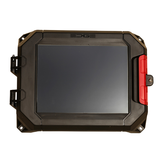
Converting EDGE 1 to EDGE 1 with
Capacitive Touch Screen
Quick Start Guide
NOTE: This guide does not provide detailed
installation, safety or operational instructions.
See the EDGE System Manuals for complete
information.
Please scan the QR Code to access the complete
manuals or visit the website:
Cumberland: http://www.cumberlandpoultry.com
AP: http://www.automatedproduction.com
The EDGE is manufactured by GSI Electronics Inc., Canada.
1 - NOTICES
Only properly trained service personnel may perform
installation and service procedures. (In other words:
electricians, service personnel employed by or active in
an organization, business, or service).
Electrostatic discharge (ESD) can damage equipment
and impair electrical circuitry. ESD damage occurs
when electronic components are improperly handled
and can result in complete or intermittent failures.
Warranty is void if the EDGE System is used in a
manner not specified by the manufacturer.
2 - SYMBOLS
WARNING: Read the following text
carefully; it contains important information
which, if ignored, may cause the controller
to operate improperly.
High Voltage. Hazard of electrical shock.
Functional Ground Terminal. Primarily
used for functional earth terminals which
are generally associated with test and
measurement circuits. These terminals are
not for safety earthing purposes but provide an earth
reference point.
Protective Earth Ground Terminal. Primarily
used for protective earth terminals. These
terminals connect to conductive parts of
a device for the purpose of safety and is intended
to be connected to an external system for protective
grounding.
3 - CONVERSION PROCESS
Electrostatic discharge (ESD) can damage
equipment and impair electrical circuitry.
ESD damage occurs when electronic
components are improperly handled and can result in
complete or intermittent failures.
Upgrade kit should include Capacitive LCD Touch
Screen, an USB Hub, USB key with firmware, and guide.
Before you begin:
Firmware version 2.8.6.263 or later is required to use
the capacitive touch screen.
Save your configuration by downloading it from
https://gsiedge.com.
IMPORTANT: Make sure all redundant and backup
systems are operating properly to provide minimum venti-
lation during the system upgrade.
1. Unlock and open EDGE 1 Main Controller cover.
2. Identify and note the cable connections to the
Alarm, Automation, and/or Safety terminal blocks.
3. Disconnect Automation and / or Safety terminal
block wires on EDGE 1 Main Controller to shut it
down.
4. Insert the supplied USB key into the EDGE 1 Main
Controller USB port.
5. Reconnect Automation and / or Safety terminal
block wires on EDGE 1 Main Controller to initiate
power. The controller should automatically begin
to update itself.
NOTE: It will take at least 5 minutes to update the
EDGE Firmware. The EDGE Main Controller will
reboot. The upgrade is completed when the main
menu screen displays.
6. After finishing the upgrade, disconnect
Automation and / or Safety terminal block wires on
EDGE 1 Main Controller to shut it down.
7. Remove the LCD Screen cables from the cable
fasteners located inside the EDGE 1 Main
Controller. From the bottom enclosure, cut tie
wraps, if needed.
4 - TROUBLESHOOTING GUIDE
Problem
Possible solution
Verify if the Touch screen cable is connected correctly
Touch Screen does not work
Verify if the EDGE 1 Main Controller has power at its terminals
If the problem persists, AP/Cumberland or GSI Electronics
Verify if the Backlight cable is connected correctly
The screen is black
Verify if the EDGE 1 Main Controller has power at its terminals
If the problem persists, AP/Cumberland or GSI Electronics
Verify if the LVDS cable is connected correctly
The backlight is only
activated
If the problem persists, contact AP/Cumberland or GSI Electronics
8. Remove the EDGE 1 Main Controller cover
(Resistive Touch LCD Screen) from the bottom
enclosure by pressing on the hinge latch
9. Install the new EDGE 1 Main Controller cover
(Capacitive Touch LCD Screen) into the EDGE 1
Main Controller bottom enclosure by pressing on
the hinge latch.
10. Remove the paper on the Velcro from the USB Hub
(item 01).
11. Connect the USB Hub Cable to the USB Hub Cable
Connector (item 02)
12. Install and stick the USB Hub (item 01) at the left
top corner of the plastic enclosure, 2 inches from
the top and ½ inch from the left side.
13. Connect the capacitive touch screen cable (item
05) to the USB Hub connector (item 01).
14. Connect the LVDS cable and its shield to the LVDS
connector (item 04) and to the shield terminal J10/
J12.
15. Connect the backlight cable and its shield to
the backlight connector (item 03) and to shield
terminal J1/J8.
16. Fasten the LCD screen cables to the enclosure
using the cables fasteners. Install new tie wraps if
needed.
17. Once the EDGE 1 Main Controller hardware is in
place, power up the EDGE 1 Main Controller by
reconnecting Automation, and / or Safety terminal
blocks.
18. Close and lock the cover.
Refer to Figure 1 on back.
GSI Electronics Inc.
5200 Armand Frappier Saint-Hubert, Qc
Canada J3Z 1G5
Phone: 1-877-926-2777
E-mail: mtl_techsupport@agcocorp.com
QSG 892-00105 REV00
AZDO886020
EN
REV 00
Advertisement

Subscribe to Our Youtube Channel
Related Manuals for GSi EDGE 1


Summary of Contents for GSi EDGE 1
- Page 1 Verify if the Touch screen cable is connected correctly measurement circuits. These terminals are Touch Screen does not work Verify if the EDGE 1 Main Controller has power at its terminals not for safety earthing purposes but provide an earth If the problem persists, AP/Cumberland or GSI Electronics reference point.
- Page 2 Figure 1 - EDGE 1 Enclosure Item # Description USB Hub USB Hub Cable Connector Backlight Connector LVDS Connector Touch Screen USB Cable (coming from the top)
Need help?
Do you have a question about the EDGE 1 and is the answer not in the manual?
Questions and answers