Table of Contents
Advertisement
ProMar
Digital
ProMariner
ProNauticP Series Instruction Manual
Models
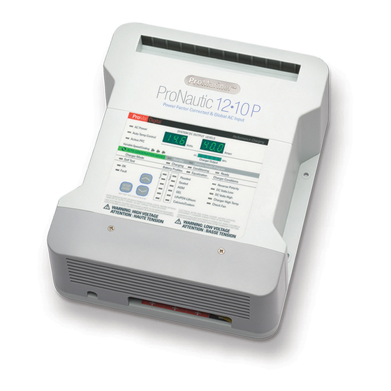
ProNautic1210P
ProNautic1215P
ProNautic1220P
ProNautic1230P
ProNautic1240P
ProNautic1250P
ProNautic1260P
ProNautic2420P
ProNautic2430P
IMPORTANT NOTICE
This manual contains important safety and operating instructions for the ProNauticP Series Chargers.
Please save and read all safety, operating and installation instructions before installing or applying
AC power to your ProNauticP Charger.
Your Satisfaction is Important to Us!
Please call our Customer Care Department at +1-800-824-0524 from 8:30 am to 5 pm Eastern
Time for any service or installation assistance. Thank you - ProMariner Customer Care
PLEASE RECORD YOUR:
Model Number: _______________ Serial Number: _______________ Date of Purchase: _______________
™
Part No.
Amperage
63110
10 Amps
63115
15 Amps
63120
20 Amps
63130
30 Amps
63140
40 Amps
63150
50 Amps
63160
60 Amps
63170
20 Amps
63180
30 Amps
Performance Charging
Global AC Input
Power Factor Corrected
100-260 VAC 50/60 Hz
energy
saving
technology
Banks
2 Banks
3 Banks
3 Banks
3 Banks
3 Banks
3 Banks
3 Banks
3 Banks
3 Banks
BC
™
Volts
12
12
12
12
12
12
12
24
24
Advertisement
Table of Contents

Related Manuals for ProMariner ProNautic1210P


Summary of Contents for ProMariner ProNautic1210P
- Page 1 Your Satisfaction is Important to Us! Please call our Customer Care Department at +1-800-824-0524 from 8:30 am to 5 pm Eastern Time for any service or installation assistance. Thank you - ProMariner Customer Care PLEASE RECORD YOUR: Model Number: _______________ Serial Number: _______________ Date of Purchase: _______________...
-
Page 2: Table Of Contents
Temperature Probe DAMAGE – If any parts are missing or damaged, or the unit has been damaged in shipping contact ProMariner Customer Service at 1-800-824-0524, please do not take it back to place of purchase. DO NOT attempt to install or operate the unit if it has been damaged in any way. -
Page 3: Introduction
Introduction ProNautic 60 P • Power Factor Corrected & Global AC Input ProMar Digital Performance Charging SYSTEM DC OUTPUT LEVELS AC Power Auto Temp Control Volts Amps Active PFC 100% Variable Speed Cooling Charger Output Standby AUTO CONSERVATION MODES Battery Health Program Charger Mode Charging Conditioning... -
Page 4: Introduction
Introduction Thank you from all of us at Professional Mariner, LLC and congratulations on the recent purchase of your ProNauticP Series On-Board Marine Battery Charger. The ProNauticP On-Board Marine Battery Charger is the latest in advanced microprocessor controlled battery charging technology and is ideal for: cuddy, cruiser, sail, house boats, yachts commercial offshore and sport fishing boats. -
Page 5: Cautions, Warnings And Safety Instructions
This manual is written to assist in the installation of your new ProNauticP Series Charger; however, since this is a permanent AC and DC hardwired installation, ProMariner strongly recommends that a Certified Marine Electrical Technician® trained by the American Boat and Yacht Council (ABYC) perform the installation. - Page 6 Warning WARNING: HIGH VOLTAGE / ATTENTION : HAUTE TENSION AVOID SERIOUS INJURY OR DEATH FROM ELECTRICAL SHOCK. BEFORE OPENING TURN OFF AC SUPPLY POWER. CHOC ELECTRIQUES PEUVENT PROVOQUER LA MORT OU DE SERIEUSE BLESSURES. AVANT D’OUVRIR LA BOITE, COUPER LE COURANT. WARNING: LOW VOLTAGE / ATTENTION : BASSE TENSION ELECTRICAL BURN AND SPARK HAZARD.
-
Page 7: Important Safety Instructions
Important Safety Instructions 7. WARNING – RISK OF EXPLOSIVE GASES. a) WORKING IN THE VICINITY OF A LEAD-ACID BATTERY IS DANGEROUS. BATTERIES GENERATE EXPLOSIVE GASES DURING NORMAL BATTERY OPERATION. FOR THIS REASON, IT IS OF UTMOST IMPORTANCE THAT EACH TIME BEFORE USING YOUR CHARGER, YOU READ THIS MANUAL AND FOLLOW THE INSTRUCTIONS EXACTLY. - Page 8 DO NOT install in an open cockpit or deck where water is a factor. NOTE: ProMariner highly recommends that this unit be installed by an ABYC Certified Electrical Technician. Guidance from ABYC E-11 AC & DC electrical systems on board boats and ABYC A-31 battery chargers and inverters is offered throughout this manual to ensure a safe, trouble free installation.
- Page 9 Otherwise, it may result in output reduction to protect internal components and the performance of the unit. Check intended installation spaces before installing to prevent unit thermal shutdown. Please note ProMariner recommends at least 6” of clearance space around all sides and the front of the charger for proper cooling.
-
Page 10: Installation
6 Amp at 120/230 VAC please use a 10 amp breaker. Charger Model 110-120 220-250 AC conductor volt breaker volt breaker size ProNautic1210P 5 Amp 5 Amp 16 AWG ProNautic1215P 10 Amp 5 Amp 16 AWG ProNautic1220P 10 Amp 5 Amp... - Page 11 Installation Please note DC organizer is color coded ensuring proper polarity connections are made. 1. Choosing Conductors – Unlike AC conductors, DC is sensitive to voltage drop, the longer the round trip, the larger the conductor needs to be. Follow the table below for your installation.
- Page 12 Fuses and holders are available through ProMariner or your local marine supply store. 3. Ground - This is extremely important and often overlooked. There is one common battery ground with the positive battery connections on the ProNauticP.
- Page 13 Installation Optional Remote Installation A remote panel is available for your ProNauticP Charger. The remote is provided with a cable and a network-type plug ProMar Digital Performance Charging connector. Pay careful attention to the routing of the cable. Power Avoid sources of heat and possible chafe when routing. Fault With the charger powered down, connect the cable to the remote port on the ProNauticP.
-
Page 14: Setup And Operation
NOTE: Factory Default charging profile is Sealed 2 (13.6 VDC Conditioning, 13.2-13.6 VDC Auto Maintain) BATTERY TYPES - A word on battery types and the ProMariner ProNauticP. As noted in the Battery Selection Table in the FEATURES section of this manual, this unit can handle 7 different types of commonly available batteries. - Page 15 Setup and Operation is a crucial step in ensuring your batteries longevity. ProMariner has pre-programmed the available settings for optimum care of whatever type of battery you find suits your application. DO NOT GUESS! If you are unsure of your battery type, contact the manufacturer of the battery.
- Page 16 Setup and Operation LED Status Indicator Center Feature LED Color Function AC power blue Auto temp control green with remote temp sensor connected Active PFC green Volts display system voltage equal to the charge in the selected profile Amps display output amperage based on state of charge Charger output percentage of charge...
- Page 17 Setup and Operation The ProNauticP is a fully automatic battery charger. The features listed below can be selected during initial set-up (see Programming section) or upon a new battery installation. Normal operation does not require any intervention from the user. See the Maintenance section for information on periodic checks.
- Page 18 Setup and Operation Charger Service Conditions DC output service Indicates a reverse polarity situation (reverse polarity) (see troubleshooting) DC volts low Amber DC system voltage is less than 11.0 VDC DC volts high Indicates a high DC voltage from an outside source such as a failed alternator/regulator Charger high temp Amber...
-
Page 19: Programming
Programming SELECTING BATTERY TYPE To select a battery type/charging profile perform the following: 1. Press and hold the SETUP/ENTER button for 5 seconds. 2. The current battery type and Voltage/Amperage displays will flash. 3. Use the keys to select desired battery type. 4. -
Page 20: Programming
Programming 3. The Voltage and Amperage displays will show “FAC” “DEF” for factory default. 4. Press the SETUP/ENTER button to confirm selection, the charger will re-boot. SELECTING THE POWER SUPPLY MODE 1. Initiate self-test by repowering unit or by pressing the SETUP/ENTER and &... -
Page 21: Troubleshooting
Troubleshooting The ProNauticP includes advanced fault indication. Faults, if indicated, may require service from ProMariner. For inquiries and service information Please call our Customer Care Department line at 1-800-824-0524 from 8:30 am to 5 pm (Eastern Standard Time) for any warranty, service or installation assistance you may need. Thank You ! THERE ARE NO USER SERVICEABLE PARTS INSIDE THE PRONAUTICP. -
Page 22: Maintenance
Maintenance This unit is solid state and requires no constant adjustment or constant attention; however, the following items should be checked: Maintenance Item Start Up Monthly Verify LED status panel shows no fault condition and indicates normal operation. Condition of fuses/breakers check for as-new condition on fuses (e.g. -
Page 23: Dimensions
Dimensions ProNauticP 12volt 10-40 Amp and 24 volt 20 Amp Dimensions Inches (mm) 7 3/4” (198 mm) ProNautic 12 40 P • Power Factor Corrected & Global AC Input 8 1/2” (215 mm) - Page 24 Dimensions ProNauticP (12 volt) 50-60 Amp and (24 volt) 30 Amp Dimensions Inches (mm) 7 3/4” (198mm) ProNautic 12 60 P • Power Factor Corrected & Global AC Input 8 1/2” (215 mm)
-
Page 25: Dimensions
Dimensions Optional Remote Dimensions Inches (mm) 3 1/2” (90 mm) 3 1/2” (90 mm) -
Page 26: Typical Wiring Configuration
Typical Wiring Configurations Typical 3 Bank12 Volt DC Common Ground Installation: ProNautic 12 60 P • Case Ground Power Factor Corrected & Global AC Input 1 Size Smaller than the + ProMar Digital Performance Charging SYSTEM DC OUTPUT LEVELS AC Power Auto Temp Control Volts Amps... - Page 27 Typical Wiring Configurations Typical 2 Bank12 Volt DC Common Ground Installation: ProNautic 12 60 P • Case Ground Power Factor Corrected & Global AC Input 1 Size Smaller than the + ProMar Digital Performance Charging SYSTEM DC OUTPUT LEVELS AC Power Auto Temp Control Volts Amps...
-
Page 28: Typical Wiring Configuration
Typical Wiring Configurations Typical Single12 Volt DC Common Ground Installation: ProNautic 12 60 P • Case Ground Power Factor Corrected & Global AC Input 1 Size Smaller than the + ProMar Digital Performance Charging SYSTEM DC OUTPUT LEVELS AC Power Auto Temp Control Volts Amps... -
Page 29: Typical Battery Capacity
Typical Battery Capacity This chart can be used as a means to properly pair your on-board battery capacity to the appropriately sized ProNauticP Marine On-Board Battery Charger. Typical Battery Capacity by Model Recommended for Sealed or Flooded Lead Batteries Part No. Model Total AH Rating 63110...
Need help?
Do you have a question about the ProNautic1210P and is the answer not in the manual?
Questions and answers
i have a 12.15P and when i plugged it in it said reverse polartiy. then all the lights lit up and shows 8.8.8. in both volts and amp windows. Can it be reset? or am I out of pocket?