Advertisement
Quick Links
Download this manual
See also:
Instruction Manual
SERVICE MANUAL
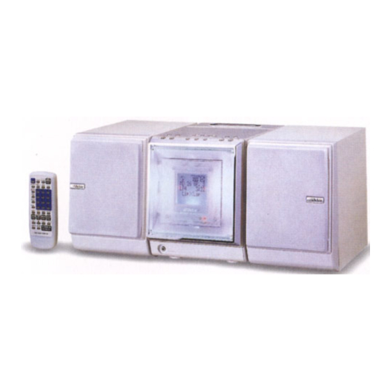
MICRO COMPONENT MD SYSTEM
COLOR
DIMMER
REV.MODE
STANDBY/ON
MD GROUP
CLOCK
/TIMER
FM MODE
SLEEP
MD TITLE
1
2
3
IMPUT/EDIT
MARK
DISPLAY
4
5
6
/CHARA
MD TITLE
7
8
9
SEARCH
SET
10
0
+
10
MICRO COMPONENT MD SYSTEM UX-F70MD
CANCEL
ENTER
REPEAT
PLAY MODE
FM/AM
CD
/AUX
TAPE
MD
BEEP
SOUND
AHB
MODE
PRO
VOLUME
RM-SUXF70MDU
PHONES
SP-UXF70MD
CA-UXF70MD
Contents
Safety precautions
Preventing static electricity
Important for laser products
Disassembly method
Adjustment Method 1
(CD/MD section)
Adjustment Method 2
(Cassette mechanism section)
Flow of functional operation
until TOC read (CD)
UX-F70MD
UX-F72MD
STANDBY/ON
COMPACT
DIGITAL AUDIO
SP-UXF70MD
1-2
1-3
1-5
1-6
1-35
1-38
1-40
This service manual is printed on 100% recycled paper.
COPYRIGHT
2001 VICTOR COMPANY OF JAPAN, LTD.
COLOR
DIMMER
REV.MODE
STANDBY/ON
CLOCK
MD GROUP
/TIMER
FM MODE
SLEEP
MD TITLE
1
2
3
IMPUT/EDIT
MARK
DISPLAY
4
5
6
/CHARA
MD TITLE
SEARCH
7
8
9
10
0
SET
+
10
MICRO COMPONENT MD SYSTEM UX-F72MD
CANCEL
ENTER
REPEAT
PLAY MODE
CD
FM/AM
TAPE
MD
/AUX
BEEP
SOUND
AHB
MODE
PRO
VOLUME
RM-SUXF70MDU
PHONES
SP-UXF72MD
CA-UXF72MD
UB
UF
Flow of functional operation
until TOC read (MD)
Maintenance of laser pickup
Replacement of laser pickup
Maintenance of MD pickup
Procedures of changing
the MD pickup
Description of major ICs
UX-F70MD/UX-F72MD
UX-F70MD/UX-F72MD
STANDBY/ON
COMPACT
DIGITAL AUDIO
SP-UXF72MD
Area Suffix
Hong Kong
China
1-41
1-42
1-42
1-43
1-43
1-44~71
No.21028
Sep. 2001
1-1
Advertisement

Related Manuals for JVC UX-F70MD


Summary of Contents for JVC UX-F70MD
- Page 1 MD TITLE IMPUT/EDIT MARK IMPUT/EDIT MARK DISPLAY DISPLAY /CHARA /CHARA MD TITLE MD TITLE SEARCH SEARCH MICRO COMPONENT MD SYSTEM UX-F70MD MICRO COMPONENT MD SYSTEM UX-F72MD CANCEL ENTER REPEAT PLAY MODE CANCEL ENTER REPEAT PLAY MODE FM/AM FM/AM TAPE /AUX...
-
Page 2: Safety Precautions
UX-F70MD/UX-F72MD Safety Precautions 1. This design of this product contains special hardware and many circuits and components specially for safety purposes. For continued protection, no changes should be made to the original design unless authorized in writing by the manufacturer. - Page 3 UX-F70MD/UX-F72MD Preventing static electricity Electrostatic discharge (ESD), which occurs when static electricity stored in the body, fabric, etc. is discharged, can destroy the laser diode in the traverse unit (optical pickup). Take care to prevent this when performing repairs. 1.1. Grounding to prevent damage by static electricity Static electricity in the work area can destroy the optical pickup (laser diode) in devices such as DVD players.
- Page 4 UX-F70MD/UX-F72MD MAIN board CN451 CN321 CD SERVO board Soldering part b Pickup 1.3. Cautions on removing the CD traverse unit * For removing the CD traverse unit in detail, refer to the "Adjustment Method" section of this manual. 1. Before disconnecting the flexible wire from the connector CN601 on the CD SERVO board, solder the part shown in the figure below.
- Page 5 UX-F70MD/UX-F72MD...
- Page 6 UX-F70MD/UX-F72MD Disassembly method <Main body> Rear cover Removing the rear cover (See Fig.1 and 2) Remove the seven screws A on the back of the body. Remove the two screws B on the bottom of the body. Antenna terminal Unlock the speaker terminal and the antenna...
- Page 7 UX-F70MD/UX-F72MD Removing cassette mechanism assembly section (See Fig.6 and 7) Cassette mechanism assembly Prior to performing the following procedure, remove Joint the rear cover and the side panels. Fan assembly Remove the two screw D on each side of the body.
- Page 8 UX-F70MD/UX-F72MD Removing the system control board (See Fig.9) Prior to performing the following procedure, remove the rear cover, the side panels and the cassette System control board mechanism assembly section. CN701 CN721 CN712 CN711 Remove the screw G on the left side of the body.
- Page 9 UX-F70MD/UX-F72MD Removing the front panel assembly Front panel assembly (See Fig.11 and 12) Prior to performing the following procedure, remove the rear cover, the side panels, the cassette mechanism assembly section and the system control board. Release the two joints d on the lower right and left sides of the front panel assembly, then remove the front panel assembly toward the front.
- Page 10 UX-F70MD/UX-F72MD Removing the main board / the heat sink CN803 (See Fig.15 to 17) Prior to performing the following procedure, remove CN804 the rear cover, the side panels, the cassette mechanism assembly section, the system control board and the MD mechanism assembly section.
- Page 11 UX-F70MD/UX-F72MD Removing power transformer Power transformer AC jack board assembly assembly (See Fig.20) CN809 Prior to performing the following procedure, remove the rear cover, the side panels, the cassette mechanism assembly section, the system control Band board, the MD mechanism assembly section and the main board.
- Page 12 UX-F70MD/UX-F72MD <MD mechanism assembly section> MD mechanism assembly Prior to performing the following procedure, remove the rear cover, the side panels, the cassette mechanism assembly section, the fan assembly and the MD mechanism assembly section. Removing the MD mechanism assembly (See Fig.24 to 26)
- Page 13 UX-F70MD/UX-F72MD <Front panel assembly section> Prior to performing the following procedure, remove the rear cover, the side panels, the cassette mechanism assembly section, the system control CN907 board and the front panel assembly section. Removing the relay board (See Fig. 27)
- Page 14 UX-F70MD/UX-F72MD Removing the door switch board Drive motor assembly (See Fig.30 and 31) Door switch board Prior to performing the following procedure, remove the relay board. Loosen the screw U attaching the door switch. Remove the door switch board while releasing it from Joint e the joint e.
- Page 15 UX-F70MD/UX-F72MD Removing the LCD board assembly Case cover (See Fig.35 to 39) Prior to performing the following procedure, remove the relay board and the LCD section. Remove the four screws W attaching the case cover. Remove the four screws X attaching the LCD panel on the back of the LCD section.
- Page 16 UX-F70MD/UX-F72MD <Cassette mechanism assembly section> Prior to performing the following procedure, remove the rear cover, the side panels and the cassette Operation switch board mechanism assembly section. Removing the operation switch board (See Fig.40) Remove the seven screws Y attaching the operation switch board on the reverse side of the cassette mechanism assembly.
- Page 17 UX-F70MD/UX-F72MD Disassembly method (Bottom) <Main body> Removing the main board Main board (See Fig.1 and 2) Turn over the body and disconnect the card wire from connector CN408 and the flexible wire from CN408 CN407 on the main board. Remove the two screws A attaching the main board.
- Page 18 UX-F70MD/UX-F72MD Removing the head lifter (See Fig.4 to 6) Move the head lifter on top of the body in the Head lifter direction of the arrow and turn around. Detach the spring from the hook of the body. Remove the head lifter with the spring.
- Page 19 UX-F70MD/UX-F72MD Removing the Loading assembly (See Fig.8 and 9) Ref: The loading assembly, the traverse mechanism assembly and the single flame will be removable after removing the loading assembly from the body. Loading assembly Prior to performing the following procedure, remove the main board, the mechanism cover, the head lifter and the head assembly.
- Page 20 UX-F70MD/UX-F72MD Slide base (R) <Loading assembly> Removing the slide base (L) / (R) (See Fig.10) Remove the two screws E on the upper side of the loading assembly. Remove the slide base (L) outward. (Release it from the joint bosses E.) Slide base (L) Remove the slide base (R) outward.
- Page 21 UX-F70MD/UX-F72MD Removing the cartridge holder assembly (See Fig.14 and 15) Remove the two screws I on the upper side of the Slide bar loading assembly. Cartridge holder assembly Eject bar Eject bar Part g Removing the slide bar and the eject bar Fig.14...
- Page 22 UX-F70MD/UX-F72MD <Traverse mechanism assembly> Insulators Removing the Insulators (See Fig.16) Pickup unit Disengage the four insulators from the notches of the traverse mechanism chassis. Insulators Traverse machanism chassis Fig.16 Joint h Pickup guide Removing the pickup unit (See Fig.17) Turn over the traverse mechanism assembly and remove the screw J attaching the shaft holder (F).
- Page 23 UX-F70MD/UX-F72MD Removing the feed motor assembly (See Fig.19-1, 19-2) Traberse mechanism board Soldering j It is not necessary to remove the pickup unit. For the white and black harnesses extending from the feed motor assembly, unsolder the soldering i on the traverse mechanism board.
- Page 24 UX-F70MD/UX-F72MD <Reattaching the loading assembly> Reattach the eject bar to the UD base. (Fig.15 and 20) Reattach the slide bar to the loading mechanism chassis while fitting the boss marked k to the eject bar slot. (Fig.20) Slide the slide bar and the eject bar in the direction of the arrow in Fig.20 and reattach the cartridge...
- Page 25 UX-F70MD/UX-F72MD Reattach the wire holder to the UD base while engaging the UD base hook marked u to the wire holder slot marked t (At the same time, the boss on the reverse side of the wire holder is fitted to the UD base round hole).
- Page 26 UX-F70MD/UX-F72MD Reattach the UD base while engaging the four pins on both sides of the UD base to the notches of the loading mechanism base and placing the edge (marked e’) of the cartridge holder assembly under the hook e of the loading mechanism base. (Fig.23)
- Page 27 UX-F70MD/UX-F72MD <Cassette Mechanism Section> Cassette mechanism Removing the Recording, Playback / Erasing Head (Refer to Figs. 1 to 3.) 1. Shifting the trigger arm seen in the right side of the head mount in the arrow-marked direction, turn the flywheel (R) counterclockwise until the head mount clicks while moving frontwards.
- Page 28 UX-F70MD/UX-F72MD Head amp. & mechanism Removing the Head Amplifier & Mechanism control P.C. board Control P.C. Board (Refer to Figs. 4 and 5.) Belt 1. Disconnect the flexible wire from the connector CN31 on the head amplifier & mechanism control P.C.
- Page 29 UX-F70MD/UX-F72MD Removing the Flywheel (Refer to Figs. 8 Flywheel (R) Flywheel (L) and 9.) Remove the head amplifier & mechanism control P.C. board. Remove the main motor assembly. 1. Remove the slit washers c and d that fasten the Capstan...
- Page 30 UX-F70MD/UX-F72MD CL. base assembly Disassembly Method Hook a <CD Mechanism Assembly> Hook a Removing the CL. Base Assembly and Tray (Refer to Figs. 1 to 5.) 1. Remove the two screws A fastening the CL. base assembly from the top of the CD mechanism assembly.
- Page 31 UX-F70MD/UX-F72MD Removing the TRAMECHA Assembly (Refer to Figs. 6 to 9.) Remove the CL. base assembly and tray. Reference: The TRAMECHA assembly can be Idle gear removed without removal of the mechanism P.C. board. TRAMECHA 1. If the TRAMECHA assembly is lowered and it is...
- Page 32 UX-F70MD/UX-F72MD Removing the Mechanism P.C. Board (Refer to Fig 10.) Flexible wire Reference:The mechanism P.C. board can be removed without removal of the TRAMECHA assembly. Shorting round Note: Before disconnecting the flexible wire coming CN601 on Soldered from the pickup from the connector, be sure to...
- Page 33 UX-F70MD/UX-F72MD Flexible wire Removing the Pickup (Refer to Figs. 11 to 14.) Shorting round Remove the CL. base assembly and tray. Remove the TRAMECHA assembly. Reference: The pickup can be removed without CN601 on removal of the mechanism P.C. board.
- Page 34 UX-F70MD/UX-F72MD Reinstalling the Pickup Assembly Part k (Refer to Figs. 15 and 16.) Part j Reference: Refer to the explanation of "Removing the Pickup" on the preceding page. Pickup assembly 1. Fit the P.S. spring and rack plate to the pickup.
- Page 35 UX-F70MD/UX-F72MD Adjustment Method 1 (CD/MD section) 1. Jigs and test instruments Laser power meter Laser power meter sensor (or disk sensor) Premastered disk (MRG-1018) Recordable disk (MDW-74/AU1) 2. Adjustment and check items 1) Indications in the modes that all LCD's are on...
- Page 36 UX-F70MD/UX-F72MD 2) MD section (2) Initializing the EEPROM Initialization of the EEPROM (For initializing the EEPROM, (1) Setup of the TEST MODE 1 it is the prerequisite that the test mode has been Press the OPEN/CLOSE While pressing both the POWER completely set up.
- Page 37 UX-F70MD/UX-F72MD (5) Adjustment of the disk Set up the MD TEST MODE 1. Press the stop key the remote controller. Insert the premastered disk. Reading of TOC ends. * If an error indication of "ERR:07" appears at the first adjustment, try...
- Page 38 UX-F70MD/UX-F72MD Adjustment Method 2 (Cassette mechanism section) Tuner section Playback/Recording & eraser head Head azimuth Head azimuth adjusting screw adjusting screw (Reverse side) (Forward side) Head azimuth Head azimuth adjusting screw adjusting screw (Reverse side) (Forward side) Playback/Recording & eraser head Removing the Cassette Mechanism Assembly 1.
- Page 39 UX-F70MD/UX-F72MD Check and Adjustment of the Head Amplifier Section Standard Adjusting Item Check/Adjustment Method Value Point 1. Head azimuth 1) Play back the end part of the test tape VT703 (10 kHz). Head Maximum 2) Adjust the head azimuth screws so that the output becomes...
- Page 40 UX-F70MD/UX-F72MD Flow of functional operation until TOC read (CD) Check Point Slider turns REST Power Key Power ON Check to see if the voltage at the SW ON. pin 72 of IC701 or pin 5 of CN602 becomes 0 V for an instant. (The...
- Page 41 UX-F70MD/UX-F72MD Flow of functional operation until TOC read (MD) Power ON MD play key Check Point Slider turns REST Confirm that the voltage Switch ON. at the pin 9 of CN408 are 0V Mechanism Operation ON Confirm that the voltage...
- Page 42 UX-F70MD/UX-F72MD Maintenance of laser pickup Replacement of laser pickup (1) Cleaning the pick up lens Befor you replace the pick up, please try to Turn off the power switch and,disconnect the clean the lens with a alcohol soaked cotton power cord from the ac outlet.
- Page 43 UX-F70MD/UX-F72MD Maintenance of MD pickup Procedures of changing the MD pickup 1. Cleaning of pickup lens Change the MD pickup by referring (1) Prior to changing the pickup, clean the pickup lens. to "Removing the MD pickup" in the Disassembly Method.
- Page 44 UX-F70MD/UX-F72MD Description of major ICs UPD784216AGF(IC701) : System micon 1. Pin layout 2. Block diagram RxD1/SI1 INTP2/NMI PROGRAMMABLE UART/IOE1 TxD1/SO1 INTP0.INTP1. INTERRUPT BAUD-RATE INTP3-INTP6 ASCK1/SCK1 CONTROLLER GENERATOR RxD2/SI2 TI00 TIMER/EVENT UART/IOE2 TxD2/SO2 TI01 COUNTER BAUD-RATE ASCK2/SCK2 (16BITS) GENERATOR CLOCKED TIMER/EVENT...
- Page 45 UX-F70MD/UX-F72MD 3. Pin function (1/2) Symbol Pin No. Description Not connected FAUX2 Not connected Not connected RDSDATA Stereo detection Stereo indicator detection TUST Not connected Tuner switch output FTUNER CD switch output Connected with VDD Not connected PB mute output...
- Page 46 UX-F70MD/UX-F72MD 3. Pin function (2/2) UPD784216AGF(2/2) Symbol Pin No. Description Reference power supply +5 V AVREF Reference power supply +5 V AVREF0 Current detection SEFTY2 Current detection SEFTY3 LDCK Function switch key input FKEY1 Destination switch input VERSION Function switch key input...
- Page 47 UX-F70MD/UX-F72MD UPD784217AGF139 (IC500) : MD micon 1. Pin layout 2. Block diagram RxD1/SI1 INTP2/NMI PROGRAMMABLE UART/IOE1 TxD1/SO1 INTP0.INTP1. INTERRUPT BAUD-RATE INTP3-INTP6 ASCK1/SCK1 CONTROLLER GENERATOR RxD2/SI2 TI00 TIMER/EVENT UART/IOE2 TxD2/SO2 TI01 COUNTER BAUD-RATE ASCK2/SCK2 (16BITS) GENERATOR CLOCKED TIMER/EVENT COUNTER1 SERIAL (8BITS)
- Page 48 UX-F70MD/UX-F72MD 3. Pin function (1/2) Pin No. Symbol Description Disk hole detection switch input (REC protection detection input) MPROT Disk innermost circumference detection limit switch on/off detection signal input SSTOP Disk detection (premaster and recordable disk) MREF Not connected Not connected...
- Page 49 UX-F70MD/UX-F72MD 3. Pin function (2/2) Symbol Pin No. Description Serial data output for external EEPROM Serial data input for external EEPROM Clock output for external EEPROM Chip select output for external EEPROM Test pin TEST Not used STS_RDY Parallel operation monitor input...
- Page 50 UX-F70MD/UX-F72MD UPD780024AGKB21 (IC251) : Unit micon 1. Pin layout 2. Pin function (1/2) Symbol Description P50/A8 Connected to GND P59/A9 Not used Pull-up +B MRDY Not used CDINDEX Not used CDEMP CD emphasis detection CDTNO CD track No. detection CDCOPY...
- Page 51 UX-F70MD/UX-F72MD 2. Pin function (2/2) Symbol Function Connected to GND P10/AN10 Analog circuit reference voltage. Connected with analog circuit power supply AVREF Analog circuit power supply AVDD CD control reset input from IC801 /RESET Not used Connected with power supply...
- Page 52 UX-F70MD/UX-F72MD CXD2662R (IC350) : DSP 1.Pin layout 2.Block diagram 16 17 18 29 27 28 90 52 CLOCK FILI XRAS GENERATOR FILO XCAS CLTV EFM / ACIRC each block ENCODER / DECODER A00~A11 COMP D0~D3 XINT SHOCK RESISTANT ASYI MEMORY CONTROLLER...
- Page 53 UX-F70MD/UX-F72MD 3.Pin function (1/3) Symbol Function Pin No. MNT0 Monitor output. MNT1 Monitor output. MNT2 Monitor output. MNT3 Monitor output. SWDT Data input for microcomputer serial interface. SCLK Shift clook input for microcomputer serial interface. XLAT Latch input for microcomputer serial interface.Latched at the falling edge.
- Page 54 UX-F70MD/UX-F72MD 3. Pin function (2/3) Symbol Function Pin No. XCAS External DRAM CAS output. External DRAM address output. XRAS External DRAM RAS output. External DRAM write enable. External DRAM data bus. External DRAM data bus. External DRAM data bus. External DRAM data bus.
- Page 55 UX-F70MD/UX-F72MD 3. Pin function (3/3) Symbol Function Pin No. SRDR Sled servo drive PWM output. ( ) SFDR Sled servo drive PWM output. (+) SPRD Spindle servo drive output. (PWM ( ) or polarity) SPFD Spindle servo drive output. (PWM (+) or PWM absolute value) FGIN Spindle CAV servo FG input.
- Page 56 UX-F70MD/UX-F72MD LC75345M-X(IC702) : E. volume 1. Pin layout & Block diagram ROUT LOUT RBASS2 LBASS2 RBASS1 LBASS1 RTRE LTRE RVRIN LVRIN RSEL0 LSEL0 1-56...
- Page 57 UX-F70MD/UX-F72MD 2. Block diagram Pin No. Symbol Description Serial data/clock input terminal Chip enable terminal LOPOUT Op-amp output LINM Op-amp inverse input LINP Op-amp non-inverse input LOUT C-connector terminal comprising volume + equalizer output and super-bass filter Super-bass band filter C & R connector terminal LBASS2 Bass band filter C &...
- Page 58 UX-F70MD/UX-F72MD CXA2523AR (IC310) : MD servo 1.Block diagram ADIP Amp TE/SE Amp PEAK 3TADJ FE Amp RFAGC 22 EQADJ AGCI 21 VREF COMPO 20 F0CNT COMPP 19 XSTBY ADDC 18 XLAT 17 SCLK Command I/F 16 SWDT 15 TEMP R...
- Page 59 UX-F70MD/UX-F72MD Symbol Function Pin No. Reference voltage output. VREF Equalizer center frequency setting pin. EQADJ BPF3T center frequency setting pin. 3TADJ Power supply. BPF22 center frequency setting pin. WBLADJ Tracking error signal output. Connects the sled error signal LPF capacitor.
- Page 60 UX-F70MD/UX-F72MD AK4519VF-X (IC480) : A / D D / A converter 1.Pin layout 2.Block diagram VA AGND VB VD DGND AINL Decimation Clock MCLK Modulator VCML Filter Divider CMODE AINR LRCK Decimation Modulator VCMR SCLK Filter VRAD Serial I/O SDTO...
- Page 61 UX-F70MD/UX-F72MD AN22000A(IC601):RF & SERVO AMP 1. Pin layout 2. Block diagram RF IN OFTR C.AGC CBDO COFTR RF OUT OFTR RF_EQ 3TENV NRFDET 3TOUT NRFDET SUBT FEOUT SUBT TEOUT TEBPF VDET VDET VREF GCTL TBAL FBAL CDDG VCC 3. Pin function...
- Page 62 UX-F70MD/UX-F72MD AN7317(IC32) : ALC & Pre Amplifier Pre-in Pre-NF Pre-out Rec-in Rec-out Rec-Mute R.R. 112k Mute R.R. AN7317 A L C 112k Pre-in Pre-NF Pre-out Rec-in Rec-out Low-cut Time Pin No. Pin Descriptions Channel 1 Playback Amplifier Input Channel 1 Playback Amplifier Negative Freedback...
- Page 63 UX-F70MD/UX-F72MD LA1838 (IC1): FM AM IF AMP&detector, FM MPX decoder 1. Block Diagram DECODER RF.AMP ANIT-BIRDIE MUTE BUFF STEREO P-DET AM IF PILOT 384KHz COMP S-METER AM/FM S-CLRVE S-METER IF-BUFF TUNING STEREO DRIVE DRIVE FM IF 2. Pin Function Symbol...
- Page 64 UX-F70MD/UX-F72MD LA6541-X (IC801) : Servo driver 1. Pin Layout & block diagram Vref Vin4 Vin3 Level B T L B T L Level RESET shift driver driver shift Level B T L B T L Level Regulator shift driver driver...
- Page 65 UX-F70MD/UX-F72MD LC72136N (IC2) : PLL frequency synthesizer 1. Pin layout FM/AM LPFOUT LPFIN CLOCK FM/ST/VCO FMIN AM/FM AMIN IFCONT SDIN IFIN 2. Block diagram Phase Reference Detector Driver Charge Pump Swallow Counter Swallow Counter 1/16,1/17 4bit 1/16,1/17 4bit Unlock Detector...
- Page 66 UX-F70MD/UX-F72MD M63008FP-X (IC410) : 5ch Actuator driver 1.Pin layout 2.Block diagram VBS1 VBS2 VBS2 IN3- VBS1 IN3+ IN1+ OUT3 IN1- CH3 IN OUT1 VBS1 VBS2 VM3(+) VM1(+) Vrefm1 Vrefm2 VM3(-) VM1(-) VBS1 VBS2 VM2(+) VM4(+) VM2(-) VM4(-) VREFO OUT2 HI :Sleep...
- Page 67 UX-F70MD/UX-F72MD BU4094B(IC33):Serial to parallel port extension 1.Pin layout 2.Block diagram STTA SDATA SDATA 8-STAGE SERIAL RECH SHIFT REGISTER OUTPUT BIAS1 SOLCTRL BIAS2 MOTOR BIAS3 RMUTE RECB 8-BIT STTA LATHES 3-STATE OUTPUT OUTPUTS ENABLE PARALLEL OUTPUT GM71VS17400CLT5(IC390) : DRAM 1. Pin layout 2.
- Page 68 UX-F70MD/UX-F72MD BR93LC66F-X(IC590):EEPROM 1. Pin layout 2. Pin function Pin No. Symbol Pin function Program enable Power supply Chip select Clock input Data input Data output Ground Non connect 3. Block diagram Supply voltage detection Command decoder control clock generation High tension...
- Page 69 UX-F70MD/UX-F72MD MN662790RSC (IC651) : Digital servo & Digital signal processer 1. Pin layout 2. Pin function Symbol Symbol I/O Description Description BCLK Bit clock output for SRDATA output (pin 3) PLLF2 PLL loop filter characteristic switching terminal LRCK L/R discrimination signal output...
- Page 70 UX-F70MD/UX-F72MD LA4628 (IC801) : Power amp. 1. Pin layout 2. Block diagram 1-70...
- Page 71 UX-F70MD/UX-F72MD L4909 (IC802) : Regulator 1. Pin layout 2. Pin function Symbol Pin No. Description REG1 feedback voltage input REG1 output voltage Input DC supply voltage VinA External SCR trigger (clover protection) TRIG Overcurrent warning output REG1 enable input REG2 enable input...
- Page 72 UX-F70MD/UX-F72MD <<MEMO>> 1-72...
- Page 73 UX-F70MD/UX-F72MD UX-F70MD/UX-F72MD VICTOR COMPANY OF JAPAN, LIMITED AUDIO & COMMUNICATION BUSINESS DIVISION PERSONAL & MOBILE NETWORK BUSINESS UNIT 10-1,1Chome,Ohwatari-machi,Maebashi-city,371-8543,Japan Printed in Japan 1-73 No.21028 200109(O)
- Page 74 UX-F70MD/UX-F72MD Block diagram IC901 MATRIX REMOCON T1002 L1006 FMA-006 IFOUT LEDCTL OSCOUT BLUE SCL,RS MUTE/IFOUT LOUT FM RF GREEN RESET FM/AM TUL,TUR ROUT FM/AM SQIN FMDET RY801 CN918 ST/MONO AM DET AMOSC CN908 CN808 TUDATA AMRF AM RF TUST SW201...
- Page 75 UX-F70MD/UX-F72MD UX-F70MD/UX-F72MD Standard schematic diagrams Main & control circuit CD SIGNAL MD SIGNAL MAIN SIGNAL TAPE P. B. SIGNAL FM/TUNER SIGNAL...
- Page 76 UX-F70MD/UX-F72MD Power amplifier & Power supply circuit Parts are safety assurance parts. When replacing those parts make MAIN SIGNAL sure to use the specified one.
- Page 77 UX-F70MD/UX-F72MD UX-F70MD/UX-F72MD MD control circuit C323 0.0068 C325 0.01 R328 R389 C327 PEAK C355 C312 47/4 C311 R327 BOTM MNT0 R361 ABCD MNT1 R362 R326 MNT2 R363 R324 TP331 MNT3 R364 R323 ADFG SWDT IC310 SCLK C322 CXA2523AR XLAT C321...
- Page 78 UX-F70MD/UX-F72MD CD control circuit R601 220k TBAL R602 FBAL C604 0.022 CN671 C603 0.022 C601 C602 0.001 0.001 SQCK R257 GCTL KCMND R259 MSTAT KCLK R263 IC251 R251 MCLK R262 R252 MDATA UPD780024AGKB21 0.1/16 R253 C256 R254 /DMUTE STAT /RESET...
- Page 79 UX-F70MD/UX-F72MD UX-F70MD/UX-F72MD Cassette control circuit 1SR139-400-T2 SG-105F3-BB,C Q201 C211 R212 DTC114TKA 0.0015 2.2K C208 R208 R211 C204 R203 R202 5.6K 4.7/25 0.033 2.4K 1.8K R204 1.2K MSI-5U2LWA QGB2011L1-10 Q203 DTC114TKA IC31 BA3126N R304 FW31 CN32 QGB2011M1-10 VWS304-06A13K R301 IC32 AN7317...
- Page 80 UX-F70MD/UX-F72MD Tuner circuit 0.0039 0.47/50 0.0022 470P 0.047 22/16 0.27 1/50 0.047 22/16 *R38 0.001 10/16 10/16 *R39 1SS133-T2 100/10 1000P *C43 1SS133-T2 *C42 3.3K VCF2L3B-105Z LC72136N 1SS133-T2 LA1838 1SS133-T2 QNB0014-001 VCF2L3B-105Z 5.6K DTA114YKA-X QQR0793-001 150P 150P 150P 1/50 1.2K 0.022...
- Page 81 UX-F70MD/UX-F72MD UX-F70MD/UX-F72MD Printed circuit boards Main board Block No. 01 Q2352 Q2351 CN743 D2351 CN744 R2206 CN705 PHOTO CN701 B2902 MGND PLAY SW10V C2218 C2307 KEY1 C2305 L2305 Q2201 SAFETY1 R2354 C2750 DGND AGND R2205 C2214 CN721 R2353 SW5V R2207...
- Page 82 UX-F70MD/UX-F72MD Power amplifier & control & AC jack board Block No. 02 D1007 C1005 D1005 R1004 L1005 RY801 USERIESONLY S1001 T1002 B1001 BZ201 S2602 S2605 S2611 OTHERSVER F1002 Z1004 Z1003 B1002 R2607 B1003 S2607 S2608 S2613 S2612 S2610 S2609 L1006...
- Page 83 UX-F70MD/UX-F72MD UX-F70MD/UX-F72MD Tuner board Block No. 03 CD servo control board Block No. 04 Forward side M851 CN651 R604 IC291 C658 CN601 Q631 C821 C606 R632 C605 R603 R805 R291 R292 R293 R809 C812 C802 R801 C611 C801 R804 C608...
- Page 84 UX-F70MD/UX-F72MD MD servo board Block No. 05 Traverse mehanism board Block No. 06 (Forward side) R328 C324 (Forward side) (Reverse side) C326 R497 C325 C321 R314 IC310 R315 C489 S602 C497 C400 C493 R306 R305 Q400 C303 K521 C300 C401...
- Page 85 UX-F70MD/UX-F72MD UX-F70MD/UX-F72MD Cassette switch board Block No. 08 Head amplifier board Block No. 07 B102 R371 C376 Q375 CN32 R375 CN34 B152 D375 Q376 C307 Q371 Q372 R372 C375 R373 R205 R112 B198 C113 R111 R105 C213 R110 R212 C105...
-
Page 86: Table Of Contents
UX-F70MD/UX-F72MD PARTS LIST [ UX-F70MD ] [ UX-F72MD ] * All printed circuit boards and its assemblies are not available as service parts. Area suffix UB --------------------- Hong Kong UF ---------------------------- China - Contents - 3- 3 Exploded view of general assembly and parts list (Block No.M1) 3- 6 CD mechanism assembly and parts list (Block No.MB) - Page 87 UX-F70MD/UX-F72MD < M E M O >...
- Page 88 UX-F70MD/UX-F72MD Exploded view of general assembly and parts list Block No. System control board 71 72 Main board Operation switch LCD board Door switch Connection board H.P. jack Power supply board board Tuner board 0.2mm...
- Page 89 Item Description Parts number Parts name Q'ty Area Parts number Parts name Q'ty Area GV10076-007A FRONT PANEL 1 UX-F70MD GV40243-001A SPACER 1 STICK AT LCD HOLDER GV10076-008A FRONT PANEL 1 UX-F72MD GV40242-003A COMMON SPACER 1 MOV.PNL/TUNER/P.WIRE GV10077-001A SUB FRAME GV10081-001A...
- Page 90 CASSETTE SPRING 2 PUT AT CASS.DOOR VKL7850-002 EJECT SAFTY(R) VKW5258-003 TORSION SPRING GV10082-002A SIDE PANEL(L) 1 UX-F72MD GV10082-001A SIDE PANEL(L) 1 UX-F70MD GV10083-001A SIDE PANEL(R) 1 UX-F70MD GV10083-002A SIDE PANEL(R) 1 UX-F72MD GV10085-001A REAR COVER QYSBSF3010N TAP SCREW 6 FOR REAR COVER...
-
Page 91: Cd Mechanism Assembly And Parts List (Block No.mb)
UX-F70MD/UX-F72MD CD mechanism assembly and parts list Block No. FMU-N1H-2M BACK SIDE Grease UD-24H2 EM-30L LEN-320M CD servo board BACK SIDE... - Page 92 UX-F70MD/UX-F72MD Parts list (CD mechanism) Block No. MBMM Item Description Parts number Parts name Q'ty Area LV32649-005A L.BASE ASSY LV32651-002A CH.BASE ASSY FEED MOTOR QAR0176-001 VKZ4743-001 SPECIAL SCREW LV42229-001A MOTOR GEAR OPTIMA-725B1 CD PICK UP LV20993-002A RACK PLATE QYSPSGT1735M MINI SCREW E406777-002SM C.D SHAFT...
-
Page 93: Md Mechanism Assembly And Parts List (Block No.me)
UX-F70MD/UX-F72MD MD mechanism assembly and parts list Block No. FMU-S5M-2M Grease =EM-30L =CFD-4007ZY2 10.0 0.2mm 38 40 61.5 0.1mm MD cam switch board 7.0 0.2mm MD servo contro board... - Page 94 UX-F70MD/UX-F72MD Parts list (MD mechanism) Block No. MEMM Item Description Parts number Parts name Q'ty Area LV20548-013A LOADING ASSY LV31472-002A CAM GEAR SLIT WASHER QYWDL1230252 LV41477-002A MINI TAP SCREW 2 CAM SW PWB LV32168-002A WIRE HOLDER LV31710-002A L.MOTOR ASSY QAR0144-001...
- Page 95 UX-F70MD/UX-F72MD Parts list (MD mechanism) Block No. MEMM Item Description Parts number Parts name Q'ty Area WJT0042-001A E-CARD WIRE LV41477-002A MINI TAP SCREW 1 T.MECHA PWB LV40761-003A INSULATOR QAH0039-002 MD HEAD 1 H601 QYSPSPT1740N MINI SCREW 1 MD HEAD LV31487-002A...
-
Page 96: Cassette Mechanism Assembly And Parts List (Block No.mp)
UX-F70MD/UX-F72MD Cassette mechanism assembly and parts list Block No. SLC-S21M Grease = EM-30L =UD-24 =UD-24H2 =LEN-320M =JC-888B =MOBIL-1 The lower side Switch board Head amplifier board 3-11... - Page 97 UX-F70MD/UX-F72MD Parts list (Cassette mechanism) Block No. MPMM Item Description Parts number Parts name Q'ty Area VKS1165-00J CHASSIS B.ASS'Y VKS2274-002 REEL GEAR B.T. SPRING VKW5286-002 VKS5559-001 PLAY IDLE GEAR VKS5597-00B BLIND VKW5296-001 EARTH SPRING SLC-RP1SVM HEAD MOUNT ASSY VKY3149-002 CASSETTE SP.
- Page 98 UX-F70MD/UX-F72MD Electrical parts list (System control board) Block No. 01 Item Remarks Item Remarks Parts number Parts name Area Parts number Parts name Area B2526 QRE141J-221Y C RESISTOR 220 5% 1/4W C2216 QCBB1HK-151Y C CAPACITOR 150PF 10% 50V BZ201 QAN0045-001...
- Page 99 UX-F70MD/UX-F72MD Electrical parts list (System control board) Block No. 01 Item Remarks Item Remarks Parts number Parts name Area Parts number Parts name Area D2602 SPR-39MVWF Q2709 KTC3875/GR/-X TRANSISTOR D2701 1SS133-T2 SI DIODE US5V Q2710 KTC3875/GR/-X TRANSISTOR D2702 1SS133-T2 SI DIODE...
- Page 100 UX-F70MD/UX-F72MD Electrical parts list (System control board) Block No. 01 Item Remarks Item Remarks Parts number Parts name Area Parts number Parts name Area R2072 NRSA63J-101X MG RESISTOR R2234 NRSA63J-103X MG RESISTOR R2235 NRSA63J-513X MG RESISTOR R2073 NRSA63J-101X MG RESISTOR...
- Page 101 UX-F70MD/UX-F72MD Electrical parts list (Main board) Block No. 02 Item Remarks Item Remarks Parts number Parts name Area Parts number Parts name Area CN801 QGB2510K2-12 CONNECTOR C1706 QENC1EM-106Z NP E CAPACITOR 10MF 20% 25V CN802 QGB2510K2-12 CONNECTOR C1707 QENC1EM-106Z NP E CAPACITOR...
- Page 102 UX-F70MD/UX-F72MD Electrical parts list (Main board) Block No. 02 Item Remarks Item Remarks Parts number Parts name Area Parts number Parts name Area L1006 QQR1145-001 LINE FILTER EMC FILTER R1802 QRE141J-681Y C RESISTOR 680 5% 1/4W L1101 QQR0797-001 INDUCTOR R1803...
- Page 103 UX-F70MD/UX-F72MD Electrical parts list (Tuner board) Block No. 03 Item Remarks Item Remarks Parts number Parts name Area Parts number Parts name Area NCB21HK-223X C CAPACITOR IC 2 LC72136N NCB21HK-103X C CAPACITOR QNB0014-001 ANT TERMINAL EETC1CM-106ZJC E CAPACITOR QQR0796-002 COIL BLOCK...
- Page 104 UX-F70MD/UX-F72MD Electrical parts list (CD servo board) Block No. 04 Item Remarks Item Remarks Parts number Parts name Area Parts number Parts name Area C 254 QERF1AM-476Z E CAPACITOR 47MF 20% 10V C 862 NCB31HK-102X C CAPACITOR C 255 NCB31CK-104X...
- Page 105 UX-F70MD/UX-F72MD Electrical parts list (CD servo board) Block No. 04 Item Remarks Parts number Parts name Area R 634 NRSA63J-3R9X MG RESISTOR R 635 NRSA63J-100X MG RESISTOR R 636 NRSA63J-151X MG RESISTOR R 651 NRSA63J-102X MG RESISTOR R 652 NRSA63J-102X...
- Page 106 UX-F70MD/UX-F72MD Electrical parts list (MD servo control board) Block No. 05 Item Remarks Item Remarks Parts number Parts name Area Parts number Parts name Area C 300 NCF31CZ-104X C CAPACITOR C 455 NDC32AJ-101X C CAPACITOR C 302 NCF31CZ-104X C CAPACITOR...
- Page 107 UX-F70MD/UX-F72MD Electrical parts list (MD servo control board) Block No. 05 Item Remarks Item Remarks Parts number Parts name Area Parts number Parts name Area Q 330 2SA1362/G/-X TRANSISTOR R 380 NRSA63J-105X MG RESISTOR Q 331 KRA102S-X D TRANSISTOR R 381...
-
Page 108: Electrical Parts List (Block No.01~08)
UX-F70MD/UX-F72MD Electrical parts list Electrical parts list (MD servo control board) Block No. 05 Block No. 05 Item Remarks Parts number Parts name Area R 516 NRSA63J-102X MG RESISTOR R 518 NRSA63J-102X MG RESISTOR R 519 NRSA63J-102X MG RESISTOR R 520... - Page 109 UX-F70MD/UX-F72MD Electrical parts list (Head amp lifier board) Block No. 07 Item Remarks Item Remarks Parts number Parts name Area Parts number Parts name Area C 101 NCS21HJ-821X C CAPACITOR Q 371 2SA952/LK/-T TRANSISTOR MOTER+B C 102 NCS21HJ-221X C CAPACITOR...
- Page 110 UX-F70MD/UX-F72MD Electrical parts list (Cassette switch board) Block No. 08 Item Remarks Parts number Parts name Area CN 1 QGB2011L1-10 B TO B CONNECTO 1SR139-400-T2 SI DIODE IC 1 SG-105F3-BB,C PHOTO SENSER QNZ0104-001 POST PIN SW 1 QSW0832-001 LEAF SWITCH R.REC...
-
Page 111: Packing Materials And Accessories Parts List (Block No.m3,M5)
UX-F70MD/UX-F72MD Packing materials and accessories parts list Block No. Block No. A1~A10 3-26... -
Page 112: Parts List
1 COVER MOVING PA GV40168-004A SHEET 1 STICK AT C.SPAC CARTON SPACER GV30229-001A QPC02503515P POLY BAG 1 FOR INST GV20150-001A PACKING CASE 1 UX-F70MD GV20149-001A PACKING CASE 1 UX-F72MD GV10087-001A CUSHION(TOP) GV10088-001A CUSHION(BOTTOM) QPC05005015P POLY BAG 1 FOR SET GV40256-001A...
Need help?
Do you have a question about the UX-F70MD and is the answer not in the manual?
Questions and answers