Advertisement
Quick Links
HONEYWELL EXCEL 5000 OPEN SYSTEM
BEFORE INSTALLATION
The Excel 10 Fan Coil Unit (FCU) Controller is available in the
following four models:
W7752D2007 (230 Vac, with electric reheat relay),
W7752E2004 (230 Vac, without electric reheat relay),
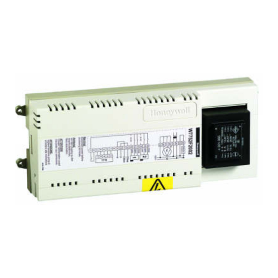
W7752F2002 (115 Vac, with electric reheat relay),
W7752G2000 (115 Vac, without electric reheat relay).
All have identical housings and mounting procedures.
IMPORTANT
It is recommended that devices be kept at room
temperature for at least 24 hours before applying
power to allow any condensation resulting from low
shipping/storage temperatures to evaporate.
This device must be installed in a UL-listed
enclosure offering adequate space to maintain the
segregation of line voltage field wiring and Class 2
field wiring (US requirement only).
INSTALLATION
Mount the Fan Coil Unit controllers in locations that allow
clearance for wiring. The controllers can be mounted on a
panel with screws or by snapping onto standard EN 50 022
DIN rail, 1-3/8 by 9/32 in. (35 mm by 7.5 mm). See Fig. 1 for
Fig. 1. Excel 10 Fan Coil Unit Controller outside and mounting dimensions in in. (mm)
® U.S. Registered Trademark
Copyright © 2011 Honeywell Inc. ▪ All Rights Reserved
W7752D,E,F,G FAN COIL UNIT CONTROLLERS
mounting dimensions. See Fig. 2 for DIN rail mounting. The
type and length of screw required for screw mounting
depends upon the panel material used to mount the con-
troller.
The controller can be mounted either vertically or horizontally.
However, if thermal actuators are connected to the controller
outputs, it is recommended that the controller be mounted so
that the transformer is not located beneath the electronics.
WARNING
ELECTRICAL SHOCK HAZARD.
Source power at terminal block can cause personal
injury or death. W7752 FCU Controllers must be
mounted inside their respective fan coil unit boxes to
prevent access by unauthorized personnel.
To reduce the risk of fire or electric shock, install in a
controlled environment relatively free of contaminants.
Wiring
All wiring must comply with applicable electrical codes and
ordinances. Refer to job or manufacturers' drawings for
details.
Excel 10
INSTALLATION INSTRUCTIONS
EN1B-0250GE51 R0111B
Advertisement

Related Manuals for Honeywell W7752D2007


Summary of Contents for Honeywell W7752D2007
- Page 1 DIN rail, 1-3/8 by 9/32 in. (35 mm by 7.5 mm). See Fig. 1 for Fig. 1. Excel 10 Fan Coil Unit Controller outside and mounting dimensions in in. (mm) ® U.S. Registered Trademark Copyright © 2011 Honeywell Inc. ▪ All Rights Reserved EN1B-0250GE51 R0111B...
- Page 2 IV 22 AWG (Belden part number 9H2201504) non- shock or equipment damage. shielded, twisted-pair, solid-conductor wire. When possible, use Honeywell AK3781, AK3782, AK3791, or AK3792 cable (US part numbers). See Excel 50/5000 L Use the heaviest gauge wire available, up to 14 AWG (2.5 ORKS Mechanisms (EN0B-0270GE51) for details, including max.
- Page 3 W7752D,E,F,G FAN COIL UNIT CONTROLLERS − INSTALLATION INSTRUCTIONS Wiring Details Fig. 6 illustrates the terminal assignments of the controllers. Table 1 lists Triac output assignments for various actuator Connections to the FCU controllers are made at two terminal types. Refer to job drawings for specific wiring diagrams. blocks protected by a plastic cover.
- Page 4 — 24 Vac ON/OFF — Manufactured for and on behalf of the Environmental and Combustion Controls Division of Honeywell Technologies Sàrl, Rolle, Z.A. La Pièce 16, Switzerland by its Authorized Representative: Automation and Control Solutions Honeywell GmbH Böblinger Strasse 17 71101 Schönaich / Germany...