Table of Contents
Advertisement
Quick Links
Advertisement
Table of Contents

Related Manuals for EFOY 1600


Summary of Contents for EFOY 1600
- Page 1 Installation Manual for RVs IM1 1600 | 1200 | 600 Automatic Charge Control...
- Page 2 Thank you for purchasing an EFOY product. We hope that you will enjoy your new unit. Please read these instructions first before using and always keep them nearby. Be sure to follow all directions in the instructions and in this installation manual.
-
Page 3: Introduction
Use only original EFOY equipment. Do not store unit and fuel cartridges at temperatures above 45° C. Do not operate at temperatures above 40°... - Page 4 1. Introduction Installation should be carried out by trained personnel only. Wear proper work clothes. Avoid flowing garments and wear a hair net if you have long hair. Clothing and hair can get caught in moving or rotating parts such as in a drill.
-
Page 5: Tools And Materials
1. Introduction Tools and Materials You will need the following tools and sealants to install the fuel cell in an RV: electric drill jigsaw screwdriver hexagonal (Allen) wrench sealant such as Sikaflex Use the following screws, depending on the mounting surface (screws are not included): 8 screws to attach the mounting plate 4 screws to attach the remote control... -
Page 6: Table Of Contents
Table of Content 1. Introduction General Instructions Tools and Materials 2. Installing the Unit Standard Equipment Locations Notes on choosing a location Securing the Unit Off-heat duct Connecting the Exhaust Hose 3. Mounting the Remote Control Mounting the Remote Control Connecting the Remote Control 4. -
Page 7: Installing The Unit
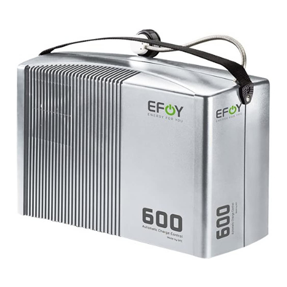
2. Installing the Unit Installing the Unit Standard Equipment Standard Equipment: Unit Remote control with data line RC1 Fuel-cartridge holder with belt FH1 Unit Mounting plate with belt MP1 Exhaust hose (1.5 m) EH1 Off-heat duct (consists of off-heat flange, off-heat bow, off-heat tube, orifice and fixing screws) OD1 Service kit (G-fuse 250V 8A m, 5 x 20 mm and service Remote control with data line... -
Page 8: Locations
2. Installing the Unit Locations Ideas for installation: false floor or side compartment seat bench rear storage area Notes on choosing a location Make sure when choosing a location, that the temperature ranges between –20° C and +40° C. This unit generates heat, thus requiring ventilation. Please take this into account when considering possible locations. - Page 9 (30 cm) and that the hose is neither kinked nor crushed. The fuel-cartridge hose and the exhaust hose may not be damaged. Do not substitute another hose for either of the two. Use only original-equipment EFOY hoses.
-
Page 10: Securing The Unit
2. Installing the Unit Securing the Unit 1. Run the belt in the groove under the mounting plate. 2. Secure the mounting plate tightly to the desired location. Use eight proper screws and dowels, if necessary, so that the mounting plate cannot shake loose in case of an accident. -
Page 11: Off-Heat Duct
2. Installing the Unit Off-heat duct The off-heat duct (included) extracts warm air so that the unit can also be operated in close quarters. Use the bow to conduct warm air to the side. cooling Zuluft If you do not need the off-heat bow, you can disconnect it from the off-heat flange and connect the off-heat tube directly to the flange. - Page 12 2. Installing the Unit Pass the off-heat tube through the opening; any excess may be shortened. It may be necessary to use an external face plate to protect the outlet. Use a suitable sealant to prevent moisture from penetrating into the body or into the interior.
-
Page 13: Connecting The Exhaust Hose
2. Installing the Unit Connecting the Exhaust Hose Exhaust gasses contain moisture and may exceed 60° C, causing scalding. Exhaust byproducts may contain injurious substances. Avoid inhaling exhaust directly or for long periods of time. The exhaust hose may not be longer than 50 cm in order to prevent freezing in winter. -
Page 14: Mounting The Remote Control
3. Mounting the Remote Control Mounting the Remote Control Mounting the Remote Control The remote control (1) displays the current status and is used to control the device. Mount the panel where it is easily accessible such as in the cockpit. If installing the panel flush with the surface of the unit, make sure that there is a sufficient opening for the electronic components behind the opening. -
Page 15: Connecting The Remote Control
3. Mounting the Remote Control Connecting the Remote Control Connect the remote control with the DL data line (included). If the DL 1 data line is not long enough, you can replace it with a commercially available network line that is longer or shorter (Category 5 patch cable). -
Page 16: Electrical Connections
4. Electrical Connections Electrical Connections Electrical Connections All work should be carried out by qualified technicians in accordance with technical regulations. Improper connections or the use of wrong gauge wires could result in fire. All wires must be properly insulated and have adequate voltage rating. -
Page 17: Connection Via The Central Electrical Box (Ebl)
4. Electrical Connections 4.1.1 Connection via the Central Electrical Box (EBL) entertainment refrigerators heating light Power lead Sense lead... - Page 18 4. Electrical Connections brown Fuse 2A unit connecting line to fuel cell extension sense line (optional) battery fuse 2 A battery (a capacity of 40 – 200 Ah is recommended) extension power line with 2- or 3- pole plug (optional) Central electrical box (EBL)
-
Page 19: Connection Directly To The Battery
4. Electrical Connections 4.1.2 Connection directly to the battery entertainment light heating refrigerators power lead sense lead... - Page 20 4. Electrical Connections brown Fuse 2A Fuse 7.5A unit connecting line to fuel cell extension sense line (optional) battery fuse sense 2 A battery (a capacity of 40 – 200 Ah is recommended) extension power line with 3-pole plug (optional) battery fuse power 7.5 A...
-
Page 21: Installing The Fuel Cartridge
5. Installing the Fuel Cartridge Installing the Fuel Cartridge Installing the fuel-cartridge holder Keep fuel cartridge and all reserve cartridges away from children. Keep cartridges away from heat and out of direct sunshine. Secure fuel cartridge and all reserve cartridges so that they can not shift. -
Page 22: Connecting The Fuel Cartridge
5. Installing the Fuel Cartridge Connecting the Fuel Cartridge For safety’s sake, use only original EFOY fuel cartridges. Do not smoke while changing the cartridge and avoid open flames! Do not expose fuel cartridges to temperatures above 45°C. Original-equipment EFOY fuel cartridges contain EFOY- approved methanol. - Page 23 6. Notes...
- Page 24 6. Notes...
- Page 25 6. Notes...
- Page 26 ©EFOY is a registrated trademark of SFC Smart Fuel Cell AG.
Need help?
Do you have a question about the 1600 and is the answer not in the manual?
Questions and answers