Table of Contents
Advertisement
Advertisement
Table of Contents

Related Manuals for CSI Dual Band BDA


Summary of Contents for CSI Dual Band BDA
- Page 1 CSI Bi-directional Amplifier CSI Bi-Directional Amplifier...
-
Page 2: Table Of Contents
Table Of Contents Product Registration/Certification Information ....1 Safety Guidelines ............1 Product Information ............2 Pin-Out Chart ........... 2 LED Indicators..........2 Mechanical Outline Drawing ......3 Installation..............4 Important Safety Information .......... 5 Performance Adjustment ..........6-17 View Menu Series ..........7-11 View Menu Flow Diagram ......... -
Page 3: Product Registration/Certification Information
DISCLAIMER: All information and statements contained herein are accurate to the best of the knowledge of Cellular Specialties, Inc. (CSI), but Cellular Specialties makes no warranty with respect there to, including without limitation any results which may be obtained from the products described herein or the infringement by such products of any proprietary rights of any persons. -
Page 4: Product Information
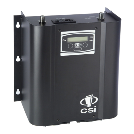
Product Description Cellular Specialties, Inc. (CSI) developed the LCD Model Bi-Directional Amplifier (BDA) for use in enclosed structures where sufficient signal from local cell sites to operate cell phones was unavailable within the building. It is necessary that sufficient signal be available on the roof of the structure. The BDA is connected to an external antenna, usually on the roof, and to one or more internal antennas placed strategically throughout the area where phone service is desired. -
Page 5: Mechanical Outline Drawing
LCD Model Mechanical Drawing Dual Band BDA M E N U Single Band BDA - 3 -... -
Page 6: Installation
Accessories are available directly from Cellular Specialties, Inc. or any of CSI’s distributors. • Outside High Gain Yagi Antennas PCS – model number (CSI-AY/1.85-1.99/10) SMR and Cellular – model number (CSI-AY/806-960/11) and (CSI-AY/806-960/14) SMR 700 - model number (CSI-AY/700-960/11) (Andrew) DD-498-PS 746-806 9-1-11 • Inside Omnidirectional Antennas PCS –... -
Page 7: Important Safety Information
Important Installation Notes • A high degree of isolation must be afforded to prevent any re-generative feedBack in the system. FeedBack of this nature causes the amplifier to emit a continuous signal of maximum amplitude and could, in some cases, interfere with normal operation of the cell site. -
Page 8: Performance Adjustment
Performance Adjustment The menu system can be navigated with five buttons: UP, DOWN, EDIT, SAVE, and MENU. Feedback is given to the operator through the LCD panel. The LCD Command Interface offers two distinct series of menus: the View Menu Series, which allow a user to view, but not alter, certain bits of data the unit maintains;... -
Page 9: View Menu Series
The View Menu Series View Menu Tree Screen Saver any key Page 8 Power Readings Page 8 MENU Oscillation Events Page 9 MENU Fan Events Page 10 MENU Overheat Events Page 10 MENU T his ser ies of m enus w i ll al low Peak Power t he use r t o v i ew , but not al t er , Readout... - Page 10 Screen Saver Display Upon powering up the BDA, a display resembling this will appear on the LCD panel: The first row contains the network name of the BDA; this allows the user to determine which BDA they are looking at. This name can be changed to whatever the user desires, and can contain blank spaces, capital letters, lowercase letters, and numerals.
- Page 11 Event Readout Displays Three performance measures are tracked within the BDA, and are recorded and displayed as events. Up to 999 of each type of event is recorded. If more than this number of events are detected, the menu system will continue to display 999.
- Page 12 recorded for each instance. A yellow LED will remain illuminated until the event counter is reset to zero. (This feature is not available in firmware version 1.1.0 and prior releases) • Over Temperature Limit: Amplifier junction temperature is monitored continuously. If the temperature rises above a factory determined limit, an Overheat Event will be recorded.
- Page 13 BDA Name and Address Display In addition to its name, a BDA can be uniquely identified on a network with a Web Monitor by its name. The name here is identical to the one in the Screen Saver Display. The BDA name is limited to seven characters. Each BDA accesible by a single Web Monitor on the network must have a unique address within that network between one and seven, inclusive.
-
Page 14: Edit Menu Series
The Edit Menu Series EDIT Ocillation Events Page 13 MENU EDIT Fan Events Page 13 MENU EDIT Overheat Events Page 13 MENU EDIT Edit Menu Tree Peak Power Readout Page 13 MENU DOWN Downlink Gain This series of menus will allow the user Page 13 to alter the information stored in the MENU... - Page 15 Edit Events Display These displays will show you the number of events recorded in each of three categories (Oscillation, Fans, Overheat). Each MENU button press will move to the next display. At any event category, pressing EDIT will clear the counter and rest the number of events to zero.
- Page 16 A typical downlink EDIT Display may look like this: The MENU button will take the user to the Edit Uplink Gain display. Edit Uplink Gain Display This display is functionally identical to the Edit Downlink Gain display, but alters the gain through the uplink pass band instead of the downlink pass band.
- Page 17 Example: In the above display the cursor shows that the user is at the fourth character position. In the below display the user has used the UP and DOWN buttons to select “S”. The cursor at that position will blink intermittently, alternating with the character currently stored at that position: Continuing the example, pressing UP at this point will illustrate the advancement of the character at the current position to “T”:...
- Page 18 When the BDA operation mode is returned to NORMAL, the FAULT LED will extinguish. Pressing the MENU button at this point will cause the BDA to display the Create New Password display. Create New Password Display This display will allow the user to enter a new password. The display, however, will not be viewable until password control is invoked by first pressing the proper keys simultaneously (SAVE and MENU).
- Page 19 BDA returns to the Screen Saver display. If the BDA does not detect any key presses within ten minutes of the last key press, the BDA will discard all changes made in the Edit Menu series since the last password entry and revert to the Screen Saver display.
-
Page 20: Troubleshooting
Troubleshooting All cables should be carefully checked for “shorts” and “opens”. The rooftop antenna, if directional, should be checked for proper alignment along the calculated compass heading. Typically, the directional antenna should be aimed at the same site that your handset uses in the area where the outside antenna is placed. -
Page 21: Product Warranty
One Year Limited Warranty Seller warrants that its products are transferred rightfully and with good title; that its products are free from any lawful security interest or other lien or encumbrance unknown to Buyer; and that for a period of one year from the date of installation or fifteen months from the date of original shipment, which- ever period expires first, such products will be free from defects in material and workmanship which arise under proper and normal use and service. - Page 22 960-1032-001 rev E D960-1032-001 rev D ECO 1910 ECO 1875...
Need help?
Do you have a question about the Dual Band BDA and is the answer not in the manual?
Questions and answers