Micropelt MVA-003 User Manual
Self-powered thermostatic radiator valve, itrv
Hide thumbs
Also See for MVA-003:
- User manual (21 pages) ,
- Quick start (2 pages) ,
- Quick start (2 pages)
Table of Contents
Advertisement
Quick Links
Download this manual
See also:
User Manual
User Guide
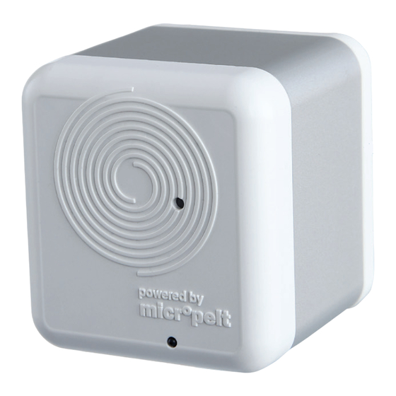
Self‐powered Thermostatic Radiator Valve, iTRV
Type MVA‐003
Dear customer,
Thank you for choosing our product. Before starting up the device, please read the entire
instructions carefully. Save the instructions for later reference and keep them together with the
device if you pass it on to someone else.
For technical support, please contact:
EH4 GmbH
Phone:
+49 7665 932 18 33
E‐mail:
info@micropelt.com
www.micropelt.com/itrv.php
Advertisement
Table of Contents

Related Manuals for Micropelt MVA-003


Summary of Contents for Micropelt MVA-003
- Page 1 User Guide Self‐powered Thermostatic Radiator Valve, iTRV Type MVA‐003 Dear customer, Thank you for choosing our product. Before starting up the device, please read the entire instructions carefully. Save the instructions for later reference and keep them together with the device if you pass it on to someone else. For technical support, please contact: EH4 GmbH Phone: +49 7665 932 18 33 E‐mail: info@micropelt.com www.micropelt.com/itrv.php...
-
Page 2: Table Of Contents
Contents USE AND SAFETY RECOMMENDATIONS INCLUDED IN THE BOX OVERVIEW System Function Proper use of the device USAGE Default setting on delivery Setting up the actuator to connect to the room controller Setting the mounting position Attaching / removing the valve actuator to the radiator Calibration cycle and wireless operation ADDITIONAL INFORMATION Powered by Energy Harvesting Status indicators and LED flash patterns Notes on radio operation RADIO PROTOCOL Protocol Data Overview Description of individual functions Example of a radio protocol TECHNICAL DATA HELP AND TROUBLESHOOTING CARE AND MAINTENANCE DISPOSAL User Guide_MVA-003_V1_0517 Page 2... -
Page 3: Use And Safety Recommendations
1 Use and Safety Recommendations The metallic part of the unit’s housing serves as a heat sink. Be sure that furniture, curtains, plants, or other objects do not obstruct the air circulation around it. If the device has been stored in a cold environment, make sure that it resumes close to room temperature before use. This is to prevent condensation from forming. The thermostatic radiator valve is designed for indoor use only. Do not allow the thermostatic radiator valve to get wet. Its sensitive electronics can be affected. The unit is best cleaned with a dry or slightly damp cloth. Do not use aggressive cleaning agents or solvents. -
Page 4: Included In The Box
2 Included in the box Self‐powered thermostatic radiator valve actuator, one unit Type: MVA‐003 Quick start instructions The connection nut of the actuator can be used universally and fits all valves with a thread size of M30 x 1.5. This covers valves of the most popular manufacturers, without requiring accessories. For other valve types normally metal adapters are available. Supported valves without adapter are: Heimeier, MNG, Junkers, Landis&Gyr (Duodyr), Honeywell‐Braukmann, Oventrop Typ A, Oventrop AV6, Schlösser, Comap D805, Valf, Sanayii, Mertik Maxitrol, Watts, Wingenroth (Wiroflex) R.B.M, Tiemme, Jaga, Siemens, Idmar, plus several others. Metal adapters are available for Danfoss valves. Please get in touch. User Guide_MVA-003_V1_0517 Page 4... -
Page 5: Overview
3 Overview 3.1 System Function The MVA‐003, a self‐powered thermostatic radiator valve, is an electronic actuator for convection radiators (standard valve type M30 x 1.5). It is designed for single room temperature control. For this purpose, the actuator is mounted on the radiator valve and linked by radio (EnOcean 868 MHz) to a suitable room controller. A connection process is used to pair the devices and a calibration cycle allows the actuator to automatically adapt its positioning range to the individual radiator valve. With the room controller set up to control the actuator, the user can conveniently configure room temperature profiles using the room controller. By lowering the room temperature during periods of absence, heating cost can be reduced without loss of comfort. The actuator can be operated in 2 modes as described in the EnOcean equipment profile A5‐20‐ 01. Either with Set point value (%) or Set target temperature (°C) using its internal temperature controller and ambient temperature sensor. It queries the room controller every 10 minutes and reports its current valve pin Setpoint value. It also receives either a new Setpoint value between 0% (valve closed all the way) and 100% (valve open all the way) or a new Set temperature value between 0°C and +40°C. The actuator’s servomotor then moves the valve pin to the new target position. The actuator generates the energy it needs for operation (running the motor and radio communication) with a built‐in thermoelectric generator (TEG). This generator draws its energy from the difference in temperature between the radiator heat and ambient air and therefore does not need an external power source, such as a battery or a wall socket, for operation. -
Page 6: Usage
Successful completion of the connection process is confirmed by a single LED flash. If the connection operation fails, the LED flashes multiple times. In this case, repeat the operation. If multiple connection attempts fail, check whether the room controller is ready to receive, then repeat the connection operation. Double‐pressing the button always causes a connection request to be sent. At the same NOTE: time, it makes the actuator move to the mounting position and stops normal radio communication. For its use with Remote Management and Commissioning please get in touch with Micropelt (EH4 GmbH) 4.3 Setting the mounting position Pressing the button twice will always bring the actuator into the mounting position (valve pin fully retracted or can be pushed in all the way without force). This is also the default‐position for storage and shipping, with power consumption being minimized since radio communication is disabled in this mode. The primary use of the mounting position however, is attachment and removal of the actuator to/from the radiator valve (see Section 4.4). -
Page 7: Attaching / Removing The Valve Actuator To The Radiator
4.4 Attaching / removing the valve actuator to the radiator You do not need to interrupt the hot water circuit and water does not have to be drained, when mounting or removing the actuator. Instead, the radiator valve remains attached to the radiator while the actuator is screwed onto the valve, typically in lieu of a traditional thermostatic head. Follow the steps below: 1. If necessary, remove the mounted thermostat by turning its union nut counterclockwise. To loosen the nut, it can be helpful to set the thermostat to maximum. 2. Remove any contamination (dust, paint) that may be present on the part of the valve that is going to attach to the actuator. 3. Be sure the actuator is in mounting position, e.g. the pin is either fully retracted or can be pushed in all the way without force. If not, then press the button twice and wait until the pin has fully moved in and the motor stops running. 4. Now place the actuator on the radiator valve. Screw on the connection nut and tighten it. Note that this step is critical to the energy harvesting performance. 5. The actuator should now rest firmly against the contact surface of the radiator valve, which is the transfer point of the heat flux to the thermoharvester. After mounting the actuator, try to gently rotate it back and forth on the valve. It should not move. 4.5 Calibration cycle and wireless operation After attaching to the radiator valve, the actuator should be in the mounting position with wireless communication stopped. -
Page 8: Additional Information
5 Additional Information 5.1 Powered by Energy Harvesting Power to the actuator is supplied by a thermoelectric generator (TEG). This extracts electrical energy from the difference in temperature between the heating water flow and the ambient air. During periods of radiator activity, excess energy is buffered in the internal energy storage device. The energy stored during the colder months of the year is used to supplement or replace the harvester output in summer as well as the spring and autumn transition periods. The storage device is sized to power the unit throughout the year, under conditions of normal heating behavior. -
Page 9: Notes On Radio Operation
5.3 Notes on radio operation 5.3.1 Transmission range The radio transmission range is limited by both the distance between transmitter and receiver, and by interference. Indoors, building materials play an important role. Major reflections and signal losses are due to metallic parts, such as reinforcements in walls and metallized foils, which are used on thermal insulation products. Penetration of radio signals: Material Penetration Wood, gypsum, uncoated glass 90..100 % Brick, chipboard 65.. 95 % Reinforced concrete 10.. 90 % Metal, aluminum facings 0.. 10 % For an evaluation of the environment, please see guide values listed below: Conditions Range / penetration Line‐of‐sight Typ 30 m range in passages, up to 100 m in halls Plasterboard and wood walls Typ 30 m range through max. 5 walls Brick and foamed concrete walls Typ 20 m range through max. 3 walls Reinforced concrete walls & ceilings Typ 10 m range through max. 1 ceiling Supply blocks and lift shafts should be treated as shields. In addition, the angle at which the signal enters the wall has to be considered. A shallow angle increases the effective wall strength as well as the attenuation of the signal. Whenever possible, signals should enter walls perpendicularly. Alcoves should be circumvented. For additional information, refer to the EnOcean White Paper “EnOcean NOTE: Wireless Systems – Range Planning Guide”. 5.3.2 Other interference sources Common sources of interference are devices that generate high‐frequency signals. These are typically computers, audio‐/video systems, electronic transformers and ballasts. The distance of the actuator to such devices should be more than 0.5 m. -
Page 10: Radio Protocol
6 Radio Protocol Bidirectional radio communication occurs periodically according to the EnOcean Equipment Profile “EEP A5‐20‐01” (Battery Powered Actuator). Communication is triggered by the actuator. 6.1 Protocol Data Overview Transmit mode from MVA‐003 to Receive mode from controller / controller/ gateway/ server gateway / server to MVA‐003 DB_3 Current valve position DB_3 New valve position 0..100%, linear 0..100% linear or n=0..100 Target temperature (0…40°C) Selection with DB_1.Bit_2‐0) DB_2.Bit_7 Not used DB_2 Room temperature from room sensor DB_2.Bit_6 Active energy DB_1.Bit_7‐4 Not used harvesting (valve is hot) DB_2.Bit_5 Energy storage DB_1.Bit_3 Summer mode, sufficiently filled transmit / receive time interval 8 hours DB_2.Bit_4‐0 Not used DB_1.Bit_2‐0 Setpoint Selection... -
Page 11: Example Of A Radio Protocol
Target temperature (°C): The room control unit transmits a target temperature between 0°C and +40°C which will be used as by the internal control loop to calculate valve positions. Valve positon (%): From the external radio master a control value of 0..100% is transmitted and the valve actuator executes a valve movement (0% = valve closed / 100% = valve open). 6.2.3 Summer Mode (DB_1.Bit_3) When the actuator receives the status message „Summer mode ON“ from the external radio master, then the valve opens and the transmit/receive interval is increased from 10 minutes to 8 hours. It is possible to wake up the iTRV through 1 x pressing the push button. Then the iTRV receives the new setting from the room controller. 6.2.4 Recognition of valve position The valve actuator recognizes during the teach‐in the closing position of the valve. During operation the valve actuator does a full stroke (self‐calibration) after every 30 movements, to avoid malfunction of the valve. It is not intended to trigger the recognition of the valve position via room controller. 6.3 Example of a radio protocol Radio protocol of valve actuator MVA‐003 to server /controller /gateway Example in HEX "0x32 0x60 0x89 0x08" DB.3 = 0x32 = 50: valve position is 50% DB.2 = 0x60: DB2.Bit_5 = 1 (Energy storage charged) / DB2.Bit_6 = 1 (Harvesting active) DB.1 = 0x89 = 137: Internal temperature = 40*DB.1/255 = 40*137/255 = 21,5 °C DB.0 = 0x08: Data telegram Radio protocol from server /controller /gateway to valve actuator Example in HEX "0x05 0x81 0x00 0x08" DB.3 = 0x05 = 5: new valve position is 5% DB.2 = 0x81 = 129: room temperature = 40*DB.2/255 = 40*129/255 = 20,2 °C DB.1 = 0x00: DB_1.Bit_3 = 0: regular radio cycle 10 Minutes (no summer mode) DB.0 = 0x08: Data telegram Example in HEX "0x80 0x81 0x04 0x08" DB.3 = 0x80 = 128: New target temperature is 20,1°C ... -
Page 12: Technical Data
7 Technical data Maximum inlet temperature 70 °C Valve type M30 x 1.5 / others via adapters Linear travel of pin / max. calibration range >3.8 mm Operating range (0 – 100%) 2.5 mm Positioning time / positioning speed 0.2 mm/s Step width < 0.1 mm Safety position Valve open > 50% Noise, normal operation < 30dBa Force of pin, normal operation 100 N typical Self‐calibration automatically Anti‐freeze safety position 95% valve open when T ambient < 5 °C Normal operation when T ambient > 5 °C Radio protocol EnOcean EEP A5‐20‐01, valve position in % (not temperature !) Carrier frequency 868 MHz Radio range approx. 30 m, depending on room situation Feedback State of charge, thermoharvester activity, valve position Radio interval, normal operation... -
Page 13: Help And Troubleshooting
8 Help and troubleshooting Issue/indication Cause Remedy The motor makes a The gear has not yet finished distinct sound during None acoustic optimization. operation No response after pressing the button Wait (if necessary overnight) until the Energy storage device is or energy storage device is recharged discharged Radiator stays hot, does again by the heat of the valve. not cool down Check mounting. Repeat calibration cycle. Test the valve with a standard Radiator does not cool thermostat head. Valve does not close all the way down If defective, contact your heating service or your property manager. Inappropriate valve adapter to M30 x 1.5. In this case please contact EH4. Vent the radiator and, if necessary, Air in the radiator check the water pressure in the heating system. Is the boiler water temperature Correct the boiler water Radiator does not heat okay ? temperature/turn on the heating Is the heating pump on ? pump. -
Page 14: Care And Maintenance
9 Care and maintenance Use a dry or slightly damp cloth for cleaning the actuator. Never use harsh cleansers or chemical solutions. 10 Disposal Do not discard the device with your household waste. Instead, drop it at an authorized collection center for scrap electronic equipment, in compliance with the Waste Electrical and Electronic Equipment Directive. User Guide_MVA-003_V1_0517 Page 14...
Need help?
Do you have a question about the MVA-003 and is the answer not in the manual?
Questions and answers