Table of Contents
Advertisement
Quick Links
Advertisement
Table of Contents

Related Manuals for Thames & Kosmos 623715


Summary of Contents for Thames & Kosmos 623715
- Page 1 E X PE R I M E NT M A N UA L WARNING — Science Education Set. This set contains chemicals and/or parts that may be harmful if misused. Read cautions on individual containers and in manual carefully. Not to be used by children except under adult supervision.
-
Page 2: Safety Information
Safety Information Dear Parents, This experiment kit will introduce your child to the exciting world of solar technology. Equipped with this manual and the material in this kit, your child could well be on his or her way to becoming a future engineer designing high-tech energy systems. But first, it is natural to have concerns about safety. - Page 3 Experiment Manual Tobias and Reihold Pehle and David Gamon Franckh-Kosmos Verlags-GmbH & Co., Stuttgart, Germany Thames & Kosmos LLC, Portsmouth, RI, USA...
- Page 4 Kit Contents The crane hook and the cord holder (28) have to be fastened to the cord.
-
Page 5: Table Of Contents
Contents List Table of Contents Tips and Tricks for Model Building and Experiments. . . Quantity and Description Part No. Follow the Instructions Closely ..... 4 2 x base plate 702 495 About Connecting Frames and Rods . -
Page 6: Tips And Tricks For Model Building And Experiments
Tips and Tricks for Model Building and Experiments Follow the Instructions Closely About Wheels and Pulleys In this box of solar experiments, you With this experiment kit, you will assemble a variety of will find four types of wheels: gear solar models and conduct a lot of experiments. It is best to short end wheels (6, 7, 8), sprocket wheels (9, 10, assemble the models in order. Then, it will be easier for you 11), pulley wheels (12, 13, 14), and tire to construct the complicated models at the end. For all the wheels (15). They all perform different models, it is important that all the individual components functions. are put together properly. Only then will everything work Gear and sprocket wheels are used right. To help you with this, there is a picture correspond- in all of the models. They have two ing to every step in the assembly process. The instructions functions: first, they serve to transfer that go with the picture tell you exactly which pieces to use. long end the rotary motion of the solar engine Following each piece mentioned in the instructions, there is to other components. Second, they a number in parentheses. This is the number that you will are used to secure axles (16, 17, 18, 19) -
Page 7: Understanding The Sun And Solar Power
Understanding the Sun and Solar Power The Sun’s Energy is about 1,700 in Los Angeles, 2,000 kWh/m in the Caribbean, and Have you ever really thought about what the Sun means to us, and what 2,200 kWh/m in the Sahara desert. Com- it does for us? Let’s start right at the pare these numbers to beginning, or more precisely, let’s start the fact that the aver- early… age American uses only about 13,500 kWh in a What happens when the Sun rises? whole year. We can do some It gets light out. The Sun produces calculations to find that light — just like a lamp, except much, The Solar Engine the Earth gets about much brighter. As you know, you need 5.45 x 10 Joules of energy from the electricity to turn on a lamp. Electricity... -
Page 8: Where Does Our Energy Come From
Where Does Our Energy Come From? Most of the energy we use comes from the Sun, in one way or another. This table provides a lot of information about our eight most popular energy sources, how they work, where they come from, and whether or not they are sustainable. Sustain- able means that they can continue indefinitely without running out or causing other problems over time. Percentage of world’s Is it renewable, power coming from relative to Name Examples Definition Energy Origin this source human life? Fossil Fuels Gasoline in a car, oil in Fossil Fuels are organic materials that release a lot The remains of prehistoric plants Petroleum: 38% No, only over mil-... -
Page 9: History Of The Solar Cell
History of the Solar Cell In 1839, the French physicist Alexandre-Edmond Becquerel discovered that light can influence electrical processes. He determined that metal electrodes immersed in acid produce more electricity when they are placed in the sunlight. Later, scientists named this the photoelectric effect, or photovol- taic effect. This was a very important discovery because it clearly showed that under certain circumstances, light can be converted into electrical energy. In 1883, an American inventor named Charles Fritts built p-n junction the first solar cell, but it was very inefficient. A lot of time passed and a lot of research was done before the first mod- ern solar cell was patented by another American named Russell Ohl. In 1958, the U.S. sent the first solar-powered satellite into space, showing how much photovoltaic tech- nology had progressed in just over 100 years. How Does a Solar Cell Work? photons (sunlight) contact layer A solar cell is a flat device that uses an electronic compo- nent called a semiconductor to convert photons, or the load (motor) massless particles of light energy, into electrical energy. The semiconductor creates a voltage, or difference in electrical potential energy, between two surfaces when it is exposed to light. You can think of it like a battery, which also has a contact layer... -
Page 10: Powering An Engine With The Energy Of The Sun
Powering an Engine with the Energy of the Sun The Solar Module Your experiment kit includes a battery holder (22) onto which the solar module is mounted. In the bat- tery holder, the electrical current is passed on to the If you are going to be a solar engineer and make use two sockets located on top of it on the left and right. of the Sun’s energy, you first need a solar cell to con- The electrical cables (20/21) are inserted into these vert light into electricity. In your experiment kit, you sockets. One cable is red, and the other is black. So will find a small solar module (23) with several solar the battery holder has two functions: it serves as cells. They are integrated into the black strips located something to attach the solar module to, as well as under the protective layer of plexiglass. If you turn the something that connects the electrical cables to the module over, you can see the individual module. You can connect all kinds of electrical equip- cells quite clearly. Your module is just ment (the technical term is “electrical load”) — most like the big ones that you see on importantly, the motor — to these cables. the roofs of houses, except that it is smaller and can’t Your New Solar Engine produce as much elec- tricity. -
Page 11: Little Shadows
Parts List 1 x base plate 1 1 x small sprocket wheel 9 1 x engine shaft 19 1 x black cable 20 1 x red cable 21 1 x battery holder 22 1 x solar module 23 1 x solar engine 24 line and the black one is the negative line. Be sure to pay attention to the plus and minus symbols on the battery holder and the engine when you attach the cables. Then take your model into bright sunlight and orient the module toward the Sun. What happens? Results As soon as enough light falls on the solar module, the engine will start to turn. Direct sunlight is bright enough to get your engine going. In shade, it isn’t bright enough — the engine won’t move. Light and shadow are like the on-off switch for the solar engine. The solar cell has the ability to convert light into electrical current, and it is this electrical current that drives the engine. The engine stops when not enough light falls on the solar module. In your house — of- ten, even right next to the window — the light isn’t Your first solar model turns the small sprocket wheel inserted onto the intense enough. The bigger a solar cell is, the more engine shaft. current it can produce. It also makes a difference how Little Shadows the solar cell is constructed. On your module, there... -
Page 12: Artificial Clouds
Your solar engine doesn’t only run in bright sunlight. It will also run on bright light from a lamp. Use a 75 Watt incandescent bulb in a desk lamp. Artificial Clouds Artificial Sun You know the story: it’s a bright sunny day, then it As you know, light isn’t only produced by the Sun. A gets cloudy and the nice weather is over. You have to lamp with an incandescent or halogen bulb can also go inside if the sky darkens with heavy black thunder- provide light. Will this kind of light also run your mo- clouds. And worst of all: your solar engine won’t work. tor? But why is it that the sunlight on an overcast day isn’t Experiment 4... -
Page 13: The Artificial Sun's Power
The Artificial Sun’s Power Ambient Light Why doesn’t the solar engine run in every part of your During the day, daylight enters your home. A term for home — even in a particularly bright room? The next this kind of light is ambient light (literally meaning experiment should shed some light on this. “surrounding light”). In the next experiment, we will see if ambient light has any effect on the solar cell. Experiment 5 > Experiment 6 You will need: solar model and a light in your > house that is strong enough to move the solar engine You will need: solar model, a long ruler, a light when you hold the engine directly beneath it in your house that is strong enough to run the solar engine when you hold the module directly beneath it. Instructions A desk lamp works the best. Hold your solar model directly under the light that Instructions is strong enough to run the engine. Then gradually increase the distance between the lamp and solar In the middle of a sunny day, hold your model under a module. What happens? light that is strong enough to run the engine. In- crease the distance until the engine stops. There has Results to be a lot of sunlight entering the room. Measure The farther away you get from the lamp, the less light the distance between the lamp and the model. Write... -
Page 14: Reverse Movement
use of this light. Even when just a little enters in, it can be used to produce electricity. But most of the time, it will be too weak to start the engine. The more light that reaches the solar cell, the more electricity it produces. Starting at a certain level of brightness, the cell will produce enough electricity to run the engine. During the day, sunlight combines with the light from the lamp. That is why the engine runs at a greater distance from the lamp than in the evening. After the Sun sets, there is no more daylight and the light from the lamp has to run the solar engine by itself. Reverse Movement You can change the rotation direction of the engine by reversing the Up to now, your solar engine has only run in one connections of the cables to either the engine or the battery holder. direction. Now we’ll find out how to make it run in reverse. Experiment 7 >... -
Page 15: Switching The Solar Module
Switching the Solar Module If it is the solar module that determines the direction of the flow of current, it should be possible to change the rotation direction of the engine by mounting the module the other way around. Experiment 8 > You will need: your solar model Instructions Run your model in bright sunlight. Note the direction of rotation of the sprocket wheel. Mount the solar module the other way around on the battery holder. What happens? Results When the module is turned around, the electricity flows in the other direction, which makes the engine run in the opposite direction as well. If you want to re- verse the direction of movement of a model — wheth- If the Sun isn’t shining, you can also run your engine with a battery. er to make a vehicle go forwards and backwards or to This should only be done when absolutely necessary, though, and not wind a cord up or down — it is easiest just to mount as a rule. -
Page 16: Your First Solar Vehicle
Your First Solar Vehicle Solar Tractor Parts List Your new solar engine works particularly well for pow- 4 x long frames 2 1 x short frame 3 ering vehicles. The first one we will build is a tractor. 1 x short rod 4 2 x medium gear wheels 7 Experiment 10 3 x small gear wheels 8 1 x small sprocket wheel 9 > 1 x medium sprocket 10 2 x long axle shafts 16 You will need: the parts from the parts list, artifi- 4 x tire wheels 15 1 x black cable 20 cial Sun 1 x engine shaft 19 1 x battery holder 22 Instructions 1 x red cable 21 1 x solar engine 24 Carefully study the tractor assembly instructions on 1 x solar module 23 8 x anchor pins 26 the following pages and follow them to assemble your 2 x shaft plugs 25 model. You will need all the parts in the list on the left. Be careful to connect the parts exactly as shown in the pictures. It is particularly important to count the holes in the rods and frames so you insert the anchor pins in exactly the right ones. For the tractor to run well, all... - Page 17 1. Insert the engine shaft (19) into the solar engine (24). The short end 2. The solar engine is mounted on a long frame (2). The engine’s of the shaft goes in the engine block. Then mount a small sprocket anchor pins go in the second, fourth, and sixth holes from the right.
- Page 18 9. Now mount the first two tire wheels (15) on the axle shafts. The 10. Now mount one tire wheel (15) on each of the axle shafts on the wheels should sit flush with the end of the axle. other side of the model. 12.
-
Page 19: Driving In Reverse
Under the Artificial Sun In the next experiments, we will find out how strong your engine is, and what kind of performance your solar module can deliver. Experiment 11 > You will need: your model, artificial Sun, smooth, flat surface such as a table top Instructions 16. Next, attach the “headlights”: Mount two medium gear wheels (7) Now place your tractor on a smooth, flat surface, on the shaft plugs. such as the top of a desk. Hold an artificial Sun — e.g., a desk lamp — directly over the solar module. Watch what the vehicle does. Results As soon as enough light strikes the solar module, your tractor starts moving. When the tractor moves beyond the cone of light, it stops: The solar module isn’t getting enough light anymore. Driving in Reverse 17. -
Page 20: A Drive In The Sunshine
On a bumpy surface, little rocks or twigs can create obstacles for your On a smooth surface, your solar vehicle runs flawlessly. Of course, the model. Unfortunately, its engine isn’t powerful enough to overcome Sun has to be shining brightly enough. them. -
Page 21: An Uphill Drive
the drawing pad just a little. What happens when the So the speed depends on the slope. Or, put different- tractor goes downhill? ly: with a slope, the engine’s force has to be applied not only to moving the tractor forward, but to moving Results it upward as well. Your tractor runs easily downhill. If you watch care- fully, you will see that it even goes a little faster than Driving with the Battery when you hold the cardboard level. On a downhill drive, the engine has to expend less energy. Can you use this effect to get your tractor to drive on a bumpy surface? So far, we have been running the tractor on solar energy. Now let’s see whether its driving performance changes when we use the battery instead of the solar Experiment 17 module. > You will need: bright sunlight, solar model, Experiment 19 bumpy ground that drops away (e.g. gravel path, pav- > ing stone with rough surface, or lawn) You will need: solar model, battery, large drawing pad or other strong cardboard, flat and slightly slop- Instructions ing bumpy ground Run your solar model in bright sunlight down a Instructions slightly sloping, bumpy surface. How does its perfor- mance change? In your model, switch out the solar module for the... -
Page 22: Load And Speed
Load and Speed Experiment 20 Conversion to a > You will need: solar tractor, 1 x base plate (1), 2 x Transport Vehicle short frame (3), 8 x anchor pins (26), bright sunlight, smooth and even surface Instructions As you know from sports, force can be applied in many different ways — to lift weights, for example, or Rebuild your tractor into a transport vehicle by add- to run fast. It’s the same with your solar engine. The ing on a large cargo bed as shown in the pictures on two most important jobs that a vehicle engine does these two pages. Run your transport vehicle in bright are to transport objects and to create speed. sunshine on a smooth, even surface — for example, In order to transport objects, your solar vehicle needs the back side of a large pad of drawing paper. What a cargo bed. For that, we will first have to rebuild your happens? tractor a little. 1. Insert four anchor pins (26) into each of the long side frames on both sides of the vehicle. -
Page 23: Adding A Load
Results Instructions The parts that you have assembled have only a mod- Collect a variety of things that you can use to load est weight to them. Simply converting the tractor to a your vehicle, such as wooden blocks or small rocks. transport vehicle should not have changed its driving Start with light objects. Check to see if your solar performance yet. transporter can carry the load. Keep increasing the weight. What happens? Adding a Load Results Your solar transporter can easily carry light objects. The more weight you add to the platform, the harder Now let’s find out how much weight your first solar it is for the vehicle. When you load on too much vehicle can handle. We can only determine how weight, the engine can’t carry the payload — your strong your solar transporter is by loading weights vehicle stays put. onto its cargo bed. The technical term is “payload.” Experiment 21 Maximum Payload > You will need: light, solar transporter, level ground, blocks or small stones as payload Of course, it would be interesting to know exactly what the maximum payload is for your transport ve- hicle. To determine that, you will need a kitchen scale. Experiment 22 > You will need: light, solar transporter, level ground, blocks or small stones as payload, kitchen scale Instructions... -
Page 24: Weight And Speed
Experiment 25 Results > Your solar transporter can’t carry as big a payload up- You will need: light, solar vehicle, a long mea- hill as it can on level ground. Since it is going uphill, suring tape, a stopwatch (you can also use a regular it not only has to move the weight in the driving direc- watch if it has a second hand), paper and pen, a firm, tion, but also upward. So the slope has a considerable flat surface (for example, an asphalt sidewalk), bright influence on its maximum payload. sunlight Experiment 24 Instructions > Mark off a distance of 1 m on the ground. Be sure that You will need: light, solar transporter, large draw- ing pad, blocks or small rocks as payload the ground is flat and that your car won’t be driving uphill or downhill. With a stopwatch, measure the Instructions amount of time that your model takes to cover the Now have your model drive down a slightly downhill distance of 1 m when it isn’t carrying a payload. Note slope. Try changing the payload and see what hap- down the number. Repeat the experiment with various pens. amounts of payload and compare the time values. Results Results Going downhill, your solar transporter can carry an The more payload you add to the cargo bed, the even heavier payload than when it drives on level slower your vehicle becomes. So there is a direct re- ground. -
Page 25: The Purpose Of Chains
The Purpose of Chains Drive Chains Joining the links can be difficult, and will require a little patience. All of your chain links are black. In the illustrations, some of the links are colored so that you Your solar transporter is moved by a gear drive. In the can easily tell them apart from the other things in the next experiment, we will take a look at another kind photos. of technology used for transferring the force of the After assembly, take your model for a drive in bright engine, namely a chain drive. sunshine. Pay attention to the way the engine’s force is transferred through the chain. Experiment 26 > Results You will need: solar transporter, 53 chain links (29), medium-sized sprocket wheel (10) You are already familiar with the principle of the chain drive from your bicycle, which also transfers force Instructions from your pedals to the rear wheel by way of a chain. Rebuild the solar transporter exactly as shown in the A chain drive is more complex than a gear drive pictures on this page. When you connect the chain — you need more parts and the mounting process is links, listen for two clicks as each link is attached to a little more difficult. So what is the advantage of the the next one. The links have two different sides: one chain drive? The answer is simple: with a chain, the is smooth, the other a little uneven. Connect the links force can be transferred over a greater distance. With so that the smooth side is on the outside. Before a gear drive, both gear wheels have to be placed right closing the chain, wrap it around the sprocket wheels. -
Page 26: Too Tight Or Too Loose
Too Tight or Too Loose Instructions Lengthen the chain by five links to 58. What happens now? The chain drive works well because the chain is just Results the right length. But what happens when the chain is too tight? The engine does run, and the chain drive works, but the chain flops around. There is a risk that it might Experiment 27 get tangled up and twisted, and jump off the sprocket > wheels. Then, your model would certainly not work You will need: solar transporter well any longer. Instructions So when you assemble your models, be sure that Remove one chain link. What happens? the chain is neither too tight nor too loose. That will ensure that they will run well. Results The chain pulls with difficulty, and even bends the Caterpillar Tracks axles a little. When that happens, the axles lose their play and can’t turn easily. The engine’s power is no longer enough to move the vehicle. And what about the opposite? What effect does a Chains can be used for other things besides drive chain have if it’s too long? chains. With many kinds of vehicles, they take the place of regular wheels. Examples of this are caterpil- lar tractors, dredgers, or some military vehicles. -
Page 27: Driving Over An Obstacle
Experiment 29 Driving Over an Obstacle > You will need: solar transporter, 140 more chain links (29), four large sprocket wheels (11) Caterpillar track vehicles show their strengths most clearly when driving over uneven terrain. We will see Instructions that in the next experiment. Convert your solar transporter into a caterpillar track Experiment 30 vehicle, as shown in the pictures on these two pages. > You will just need chain links (29) and the large You will need: your solar-powered caterpillar sprocket wheels (11). You will have to remove the track vehicle, smooth, even, slightly down-sloping cargo bed, because otherwise one side of its support surface (for example, a tilted drawing pad), a long framework would interfere with the mounting of the crayon or pencil caterpillar track. Then take your model for a drive in Instructions bright sunlight. What do you observe? Lay a long pencil or crayon across the path of your Results caterpillar track vehicle to serve as an obstacle. Let At first glance, your caterpillar track vehicle drives your vehicle get a running start and drive over the just like a vehicle with wheels. Under normal driving obstacle, while you hold the pencil or crayon in place. conditions, there do not seem to be any significant Pay close attention to what happens with the tracks differences between vehicles with caterpillar tracks... -
Page 28: Large Platform Elevator
Large Platform Elevator Raising and Lowering with the Sun The solar engine can be used for other things be- sides driving a vehicle forward and backward. With this model, we will be applying solar energy to the raising and lowering of a platform. You will be using the crane hook, cord, and spool (28). You first have to attach the cord to the spool and hook (see the pictures on p. 2). The spool will be mounted directly on the engine shaft. When you are working with the crane hook, cord, and spool, be sure that the cord doesn’t get tangled on the axles when it is wound up. Most important of all, be sure to stop the platform at the right time when you are raising or lowering it. The simplest way is to hold your hand over the solar module to prevent the cells from getting enough light. Components of the Model This large model, which is quite easy to build, actually consists of three parts. First, there is the tall support structure, assembled out of long and short frames. It is mounted securely on two base plates, which form its foundation. On top of the framework, there is (Model Car) the drive system. In addition to the engine, the solar module is mounted here. You will need a special sup- port frame for both. The third element is the elevator cage. This is con- structed from frames and rods, with two medium gear wheels inserted into the front for decoration. The cage is suspended directly from the crane hook. - Page 29 Parts List 2 x base plates 1 6 x long frames 2 6 x short frames 3 5 x short rods 4 2 x long rods 5 2 x medium gear wheels 7 1 x small gear wheel 8 1 x small sprocket wheel 9 1 x large sprocket wheel 11 1 x long axle shaft 16 1 x engine shaft 19 1 x black cable 20 1 x red cable 21 1 x battery holder 22 1 x solar module 23 1 x solar engine 24 2 x shaft plugs 25 21 x anchor pins 26 1. The foundation consists of two base plates (1). Combine these into a 2 x attachment plates 27 single surface with the attachment plates (27). 1 x crane hook with spool and cord 28 1 piece of sturdy cardboard (8 x 11 cm) 3.
- Page 30 5. Now you will construct the lift system. Insert four anchor pins into 6. Push a sprocket wheel (11) onto the axle shaft and guide the shaft two long rods (5) and insert a long axle shaft (16) through the center of through the second long rod.
- Page 31 11. The floor of the cage is made of two short frames (3) connected by a 12. Each of the side walls consists of one short frame. Take two short short rod (4). You will need to use two anchor pins (26). frames (3) and insert six anchor pins (26) as shown in the picture.
-
Page 32: Your Solar Car
Your Solar Car Solar Car Assembly Parts List This solar car is actually pretty complicated to build. 6 x long frames 2 3 x short frames 3 It is relatively wide, so the front and rear axles and 4 x short rods 4 4 x large gear wheels 6 the drive shaft have to be made out of two axle shafts 3 x medium gear wheels 7 9 x small gear wheels 8 joined together in order for them to be long enough. 4 x small sprockets 9 2 x medium sprockets 10 When lengthening the axle shafts, the important thing 1 x large sprocket 11 4 x tire wheels 15 is to have the short ends of the shafts located on the 5 x long axle shafts 16 1 x medium axle shaft 17 inside. They are inserted into a small sprocket wheel, 1 x short axle shaft 18 1 x engine shaft 19 which holds them together. Be sure that the ends 1 x black cable 20 1 x red cable 21 of both axle shafts are pushed equally far into the 1 x battery holder 22 1 x solar module 23 sprocket wheel, so the sprocket wheel is positioned 1 x solar engine 24 4 x shaft plugs 25 exactly between the two shafts. Finally, check to make 18 x anchor pins 26 43 x chain links 29 sure everything holds together solidly. - Page 33 1. Two long frames (2) connected together serve as the side sections. 2. Now mount another long frame (2) on the anchor pins in your large Then insert four anchor pins (26) into the frames and attach a short side section. Insert two more anchor pins (26) into this frame. frame (3).
- Page 34 9. The grill is made of a short frame (3) into which you stick two anchor 10. Stick two small gear wheels (8) and two medium gear wheels (7) pins (26), one short axle shaft (18), and three shaft plugs (25). onto the small axle and the three shaft plugs.
- Page 35 17. Now mount the four tire wheels (15) onto the front and rear axles. 18. For the power transmission between engine shaft and drive shaft, For looks, add a large gear wheel (6) to the outside of each one. mount a medium sprocket wheel (10) on the engine shaft and a large sprocket wheel (11) on the drive shaft.
-
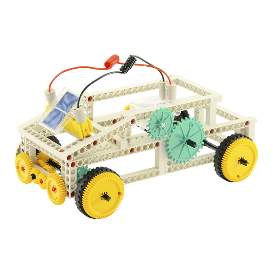
Page 36: Truck With Large Cargo Bed
Truck with Large Cargo Bed Undercover Technology Parts List This truck has command of a pure chain drive that 2 x base plates 1 4 x long frames 2 turns the wheels on the rear axle. The unusual thing 6 x short frames 3 6 x short rods 4 about it is that the transmission to the rear axle is 2 x long rods 5 2 x large gear wheels 6 practically invisible. Only the chain from the engine 4 x medium gear wheels 7 10 x small gear wheels 8 to the drive shaft is visible — the other chains are hidden by the large cargo bed. The big headlights on 4 x small sprockets 9 3 x medium sprockets 10 the front grill turn when the truck is moving. They are 4 x tire wheels 15 4 x long axle shafts 16 set in motion by the front wheels, and have no direct 2 x medium axle shafts 17 2 x short axle shafts 18 contact with the engine. The yellow gear wheels move 1 x engine shaft 19 1 x black cable 20 in reverse of the vehicle’s motion: while the truck is 1 x red cable 21 1 x battery holder 22 driving forward, they turn in the opposite direction. 1 x solar module 23 1 x solar engine 24 Another special feature is the vehicle’s moveable front 3 x shaft plugs 25 24 x anchor pins 26... - Page 37 short end short end 1. Start with a long frame (2), three anchor pins (26), one medium (17) 2. Equip a second long frame (2) with the same components, except and one long axle shaft (16), one small gear wheel, and one medium use a small gear wheel (8) instead of the medium sprocket wheel.
- Page 38 9. Attach the two frames to the short rods. They hold the cargo bed in 10. Next, place two long rods (5) on the rear of the base plate and push place, which can now no longer move up or down. them onto the side anchor pins.
- Page 39 17. Now attach the two short frames to the frame with the large gear 18. Now connect the two axle shafts with a small sprocket wheel (9) to wheels. The medium gear wheel on the inner right has to mesh with form one long axle.
-
Page 40: Large Drawbridge
Large Drawbridge Tall Bridge with Roadway Parts List Drawbridges aren’t just something found on medieval 2 x base plates 1 4 x long frames 2 castles — they are still used today for roads that go 4 x short frames 3 8 x short rods 4 over rivers and canals. When a large ship comes, the 4 x long rods 5 4 x large gear wheels 6 roadway can be raised up to let the ship pass through. 4 x medium gear wheels 7 9 x small gear wheels 8 Then, the bridge is lowered again so pedestrians and 3 x small sprockets 9 1 x medium sprocket 10 vehicles can cross over the river. 2 x large sprockets 11 1 x medium pulley wheel 13 For our next project, we will be building this kind of 5 x long axle shafts 16 2 x medium axle shafts 17 drawbridge. The actual bridge is located at the front, 1 x short axle shaft 18 1 x engine shaft 19 and it can be raised and lowered with the help of 1 x black cable 20 1 x red cable 21 the crane hook, spool, and cord. The cable is guided 1 x battery holder 22 1 x solar module 23 over a pulley wheel mounted high up the bridge. The 1 x solar engine 24 4 x shaft plugs 25 bridge is just as wide as the roadway running through 20 x anchor pins 26... - Page 41 1. First you will build the bridge. Push a small gear wheel (8) onto the 2. The bridge is the width of five short rods (4). Push all the short rods short end of a long axle shaft (16). Then push a short rod (4) onto the onto the long axle shaft.
- Page 42 9. To the rear of the frame, attach a short axle shaft (18) with a large 10. Then add a medium axle shaft (17) and two small (9) and one sprocket wheel (11). medium sprocket wheel (10) to the front. 11.
- Page 43 short end 17. Now add a medium (17) and a long axle shaft (16) along with three 18. The spool with the cord and crane hook goes on the short axle, and small gear wheels (8). a large sprocket wheel goes on the long one. 19.
- Page 44 25. To secure the battery holder, we will now attach a short frame (3) to 26. A long rod (5) goes on the frame and the battery holder (22) goes the solar engine. on the rod. 27. Now you just have to mount the solar module (23) and attach the cables (20/21).
-
Page 45: Iron Annie" Airplane
“Iron Annie” Airplane Two Directions of Movement Parts List The “Iron Annie” is one of the most famous pas- 6 x long frames 2 4 x short frames 3 senger planes in the world. In Germany, it was called 3 x short rods 4 6 x long rods 5 the “Tante Ju” — or “Auntie Ju” — with the “Ju” part 3 x large gear wheels 6 4 x medium gear wheels 7 of its name being short for German aircraft engineer 4 x small gear wheels 8 1 x small sprocket 9 Hugo Junkers. It was technically known as the “Ju 52/3m,” but it got its affectionate nickname because 1 x medium sprocket 10 2 x tire wheels 15 of its reliability. 2 x long axle shafts 16 1 x medium axle shaft 17 1 x engine shaft 19 1 x black cable 20 Iron Annie was the inspiration for this model. In this 1 x red cable 21 1 x battery holder 22 design, the solar engine moves the wheels as well as 1 x solar module 23 1 x solar engine 24 the propeller in the center. So there are different direc- 5 x shaft plugs 25 26 x anchor pins 26 tions of movement: while the wheels move forward 57 x chain links 29 or backward, the propeller moves at right angles to 2 x attachment plates 27... - Page 46 1. First build the two side pieces by combining four long frames (2) into 2. To strengthen the double frames, insert eight anchor pins (26) into two large side sections. four long rods (5). 3. Now attach the four rods with the anchor pins to the two double 4.
- Page 47 7. Now attach the two double frames together. The engine’s anchor pins will help to secure it. Make sure that the two frames sit exactly across from each other and that the front axle sits in the right hole in the new fame. 8.
- Page 48 12. Now assemble the drive chain from 57 chain links (29) and wrap the 13. To lengthen the tail of the plane, combine two short frames (3) and chain around the two sprocket wheels. insert two anchor pins (26). 14. Mount this double frame on the rear of the plane between the two 15.
- Page 49 20. Insert the axle shaft along with a small gear wheel into the center 21. Attach the rod to the front of the airplane. Adjust tires and gears of a short rod (4) with two anchor pins (26). and make sure that everything moves easily. 22.
-
Page 50: Windmill With Wind Wheels
Windmill with Wind Wheels Power Over Great Distances This very large model demonstrates how a chain From that second small wind wheel, the power is drive can be used to bridge great distances between further transferred to a larger wind wheel mounted sprocket wheels. In this case, there are three chains higher on the front side. moving three wind wheels. The construction is by no means simple, and it requires precise work. So the large wind wheel is the one that is farthest away from the solar engine. If you wanted to drive it The solar engine sits down below on the foundation, directly — without the axles in between, on the small which is made out of two base plates. At the back are wind wheels — you would have to use a very long two large frames attached together. In each of these chain indeed. But long chains can easily slip, and they frames, there is a small wind wheel. The first chain are not very sturdy. The little wind wheels have a tech- drive turns the lower wheel. On the axle that turns nical purpose: They let you use shorter chains, and this wind wheel is another sprocket wheel, which thus help to ensure a more dependable operation. drives the other small wind wheel mounted above. - Page 52 2. Now mount two short frames (3) to the base plate. They will serve as 3. A long axle shaft (16) with small (9) and large sprocket wheel (11) a support structure for the two small wind wheels. and small (8) and medium gear wheel (7) goes through the second hole of each of the frame stands.
- Page 53 7. This is where the drive for the second small wind wheel will be. You will need a small sprocket wheel (9) as well as a small (8) and medium (7) gear wheel. 9. Now it’s time to build the support structure for the large wind 8.
- Page 54 12. Prepare the assembly for the large windmill wheel by first building four identical blades. Build each of them out of one short frame (3), one short axle shaft (18), one small (8) and one large gear wheel (6), as well as one anchor pin. To connect the blades to one another, you will need two short rods (4), each with four anchor pins (26).
- Page 55 possible additional sprocket wheel 14. The two double blades are attached to the already-mounted axle shaft. Set them against the two gear wheels that are already there. Then add two more small gear wheels (8), so the blades are clamped between the gear wheels. On the outside, a medium sprocket wheel (10) completes the assembly.
-
Page 56: Mobile Crane Car
Mobile Crane Car Removable Crane Assembly The heart of the heavy crane car is the actual crane as- sembly, which can lift and lower a variety of loads with the help of the solar-driven engine and a crane hook This crane car is actually made out of two separate that is raised and lowered by the cord and spool. models: the crane assembly and the vehicle mount. A large pulley wheel mounted on its own framework That lets you transport the crane wherever it may be serves as a guide for the cord. This framework has needed. two functions. First, its height makes it possible to lift large items (for example, a long rod). Without the tall You dismount the crane assembly on site, so that it framework, the distance between pulley and crane can sit securely while lifting loads. Once you have hook would be too small, and many items couldn’t be lifted them, you remount the assembly onto the car lifted properly off the ground. so that you can carry the cargo to another location. The crane hook extends far enough over the front of crane so that it can raise loads without interference. The crane car consists of two separated models: the crane assembly The chassis serves to transport the crane assembly to where it is and the chassis it sits on. - Page 57 The frame structure also makes it possible to lift Parts List loads without banging them against the car or the gear wheels. If the long rods holding the cord pulley were to sit directly on the short frame in front, the 1 x base plate 1 3 x long frames 2 hook would always be hitting the assembly. 6 x short frames 3 7 x short rods 4 The drive machinery is held by four short frames. A 2 x long rods 5 3 x medium gear wheels 7 large frame mounted on one side serves to hold the 9 x small gear wheels 8 3 x small sprockets 9 other frames steady. The technical way to say it is that 1 x large sprocket 11 1 x large pulley wheel 12 the large frame “reinforces” the construction. The 4 x tire wheels 15 4 x long axle shafts 16 short rod holding the solar unit in the rear, as well 2 x medium axle shafts 17 1 x short axle shaft 18 as the two cross-rods on the front framework, also 1 x engine shaft 19 1 x black cable 20 contribute significantly to the reinforcement of the 1 x red cable 21 1 x battery holder 22 drive mount framework, and therefore to the crane as- 1 x solar module 23 1 x solar engine 24 sembly as a whole. 4 x shaft plugs 25 26 x anchor pins 26 42 x chain links 29 1 x anchor pin lever 30 1 x crane hook with spool and cord 28 1.
- Page 58 5. On the other side of the base plate, mount another two short frames 6. A long axle shaft (16) with small gear wheel (8) and small sprocket (3) with three anchor pins (26) on top and four on the side. wheel (9) goes through the fourth hole from the top in the frames that have just one anchor pin on the top.
- Page 59 10. Mount a long frame (2) on the four free anchor pins on the side 11. The large pulley wheel (12) is held by two short (4) and two long away from the engine. This serves to stabilize the construction. rods (5) with four anchor pins (26), along with a long axle shaft (16) with two small gear wheels (8).
- Page 60 14. The framework for the vehicle mount is made of two short (3) and 15. Once the frames are connected, attach four anchor pins (26) on two long frames (2). You will need four anchor pins (26) in order to the inside and four shaft plugs (25), which are going to hold decorative combine the frames into a rectangle.
-
Page 61: Heavy Duty Construction Crane
Heavy Duty Construction Crane “Crooked” Construction Parts List For our final project, we will build a heavy construc- 2 x base plate 1 6 x long frames 2 tion crane. The unusual thing about it is that the 6 x short frames 3 5 x short rods 4 frame sections are assembled a little crookedly, rather 6 x long rods 5 1 x large gear wheel 6 than at a right angle. This is made possible by anchor 1 x medium gear wheel 7 8 x small gear wheels 8 pins arranged so that they are offset from one an- other, with large and small frames mounted on these 2 x small sprockets 9 3 x medium sprockets 10 anchor pins. 1 x large sprocket 11 1 x medium pulley wheel 13 1 x small pulley wheel 14 4 x tire wheels 15 This crane is a very large model. That makes it all the 4 x long axle shafts 16 1 x medium axle shaft 17 more crucial that you assemble everything carefully 3 x short axle shafts 18 1 x engine shaft 19 and that you make sure that everything is attached 1 x black cable 20 1 x red cable 21 securely. Wheels, pulleys, and chains have to turn 1 x battery holder 22 1 x solar module 23 easily. The chains are very long, so be sure that their 1 x solar engine 24... - Page 62 2. Insert four anchor pins (26) into one short rod (4) and attach the rod to the left base plate. Look at the picture to see where to put the anchor pins. When you assemble the crane, it is crucial that the drive wheels are 3.
- Page 63 5. The solar engine (24) with engine shaft (19) and small sprocket 6. Now mount the frame with the engine on the base plate. Four wheel (9) sits at the lower end of a long frame (2). anchor pins (26) go into the two long frames sticking up vertically. 7.
- Page 64 11. For extra decoration, take two long rods (5) and attach a shaft plug (25) and small gear wheel (8) to the end of each. 13. Now mount the two long decorative poles on the outer frames. 12. Mount the holder (22) with the solar module (23) on the rear small Check that all the parts sit tightly and don’t wobble.
- Page 65 16. Now you’ll need a short (3) and a long frame (2), a short rod (4), 17. Now combine the two sections of the arm. Adjust the position of a long axle shaft (16), two small gear wheels (8), a small pulley wheel the small pulley wheel so that it is aligned with the crane spool.
-
Page 66: Designing Your Own Solar Models
Designing Your Own Solar Models Multiple Possibilities Stable Construction If you have built all the models in this book, you are Above all, be sure that your models have a stable a real solar engineer. You know lots of ways the solar construction. Nothing is more frustrating than when engine can be used and you have learned the function a model falls apart as soon as you try to use it. That is of all the components in the kit. particularly true for large models. Be sure to stabilize the building components sufficiently (see p. 55). For But the models that you have built are by no means models that are not mobile, it is always a good idea all the things you can make with the solar engine and to use a base plate as a foundation. It gives the model the other components. You could also, for example, stability. When assembling a model, it goes without build a tall crane, a fan, or a spaceship. Let your saying that you should never try to jam components imagination run free and invent your own models. In together by force or bend them. If two pieces aren’t all cases, the important things are that the construc- connecting or inserting easily, then you’ve construct- tion is stable and the drive systems run smoothly. ed something wrong. You can always find a different way to do it. Smooth-running Drive Systems With all drive systems, it is important that they run smoothly. Chains must be neither too loose nor too tight. The sprockets holding a chain should be lined up exactly. Otherwise, the chain will easily twist and your model won’t work well. - Page 67 US Annual Average Solar Energy received by a photovoltaic cell Source: Electric & Hydrogen Technologies & Systems Center, National Renewable Energy Lab, May 2004...
Need help?
Do you have a question about the 623715 and is the answer not in the manual?
Questions and answers