Broan BPDC1 Installation Use And Care Manual
Hide thumbs
Also See for BPDC1:
- Wiring instructions (9 pages) ,
- Installation use and care manual (28 pages)

Related Manuals for Broan BPDC1


Summary of Contents for Broan BPDC1
-
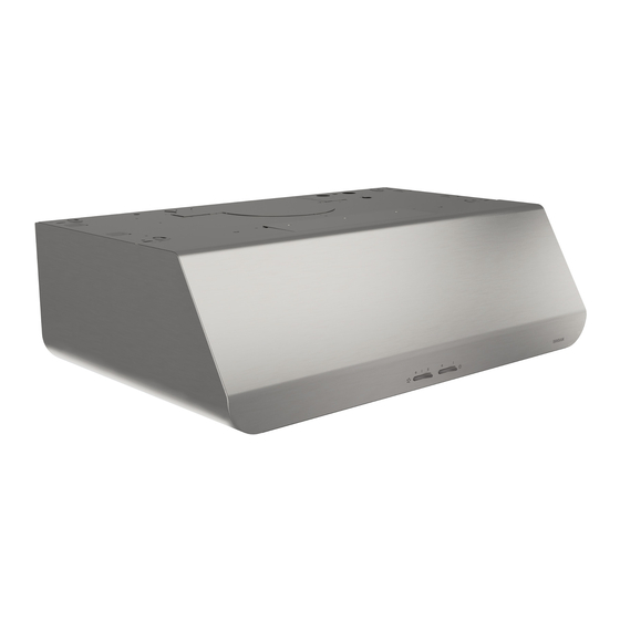
Page 1: Range Hood
WWW.BROAN.COM WWW.NUTONE.COM WWW.BROAN.CA WWW.NUTONE.CA RANGE HOOD Series: BPDC1, BPDP1 and NPDP1 INSTALLATION, USE AND CARE MANUAL Serial number: 99045656-001B... -
Page 2: Table Of Contents
Connect the Wiring ..... . 20 Install the Light Bulbs (BPDC1 Series) ..21 Install the Filters . -
Page 3: Safety
Intended for domestic cooking only INSTALLER: LEAVE THIS MANUAL WITH HOMEOWNER. For Broan products in U.S.A., register your range hood online at www.broan.com For NuTone products in U.S.A., register your range hood online at www.nutone.com For Broan products in Canada, register your range hood online at www.broan.ca For NuTone products in Canada, register your range hood online at www.nutone.ca... -
Page 4: Safety
WARNING TO REDUCE THE RISK OF A RANGE TOP GREASE FIRE: a) Never leave surface units unattended at high settings. Boilovers cause smoking and greasy spillovers that may ignite. Heat oils slowly on low or medium settings. b) Always turn hood ON when cooking at high heat or when flambeing food (i.e.: Crêpes Suzette, Cherries Jubilee, Peppercorn Beef Flambé). -
Page 5: Operation
BPDC1 SERIES BLOWER SWITCH LIGHT SWITCH Turns blower on to LOW speed. Turns light on in LOW intensity. • • Turns blower OFF. Turns light OFF. Turns blower on to HIGH speed. Turns light on to HIGH intensity. BPDP1 AND NPDP1 SERIES... -
Page 6: Cleaning And Maintenance
Cleaning and Maintenance Proper maintenance of the Range Hood will assure proper performance of the unit. MOTORS The motors are permanently lubricated and never need oiling. If the motor bearings make excessive or unusual noise, replace the motor with the exact service motor. The fan wheel should also be replaced. -
Page 7: Installation
For ADA compliance installation guidelines, please visit www.broan-nutone.com Recommended Tools and Accessories for Installation • Measuring tape • Phillips screwdriver no. 2 • Nut driver or socket 11/32” • Flat blade screwdriver (to open knockout holes) • Drill, 1/8” drill bit and 1½” hole saw (to mark holes for ducting and cut electrical access hole) •... -
Page 8: Contents
Contents Before proceeding to the installation, check the contents of the box. If items are missing or damaged, contact the manufacturer. Make sure that the following items are included: BPDC1 Series BPDP1 and NPDP1 Series IND INSIDE IND INSIDE OF HOOD OF HOOD (1) 3¼”... -
Page 9: Prepare The Hood
Prepare the Hood 1 ] If present, remove all protective polyfilm from the hood and/or parts. 2 ] Using the finger cup, remove the grease filters from the hood by pushing down and tilting filters out 3 ] Remove both fillers by removing the 3 screws holding each one of them. Slide each one towards the center of the hood and tilt it up to remove it completely. - Page 10 4 ] Remove both tape strips holding the 7” round adapter, and put the adapter aside. 5 ] Remove the screw holding the 3¼” x 10” adapter/damper and put the adapter/damper aside. Save this screw, it will be used later to hold the cover plate. 6 ] Remove the parts bag taped in the lower left corner of the hood.
- Page 11 8 ] Remove the EZ1 brackets from inside the hood by cutting off the tie wrap. Discard the tie wrap. BRACKETS 9 ] Remove Electrical Power Cable Knockout from top (vertical exhaust) or back (horizontal exhaust) of hood. For knockout removed from back of hood, install an appropriate strain relief, 1/2”...
- Page 12 DUCTED INSTALLATION ONLY 10 ] Remove 3¼” x 10” vertical, 3¼” x 10” horizontal (both are the rectangular central knockout plates, see hatched areas) or 7-inch round knockout plate as appropriate for your ducting method (see F 1 A and 1 B). IGURES IGURE IGURE...
-
Page 13: Prepare The Hood Location
Prepare the Hood Location NOTE: Before starting installation, read all the steps of these instructions. Use the illustration below to identify your kitchen cabinet type. FRAMED CABINET FRAMELESS CABINET This manual covers 2 kinds of installation: the standard (without EZ1 brackets) and the EZ1 one-person installation system (using included template and brackets). - Page 14 4 ] Drill a 1/8” dia. pilot hole for house wiring, at B location on template. 5 ] Use a sharp pencil or 1/8” drill bit to mark the locations for the appropriate duct access holes (16 locations for 7” round duct, or 4 corner locations for rectangular duct). Remove the template.
- Page 15 FRAMELESS CABINET Refer to the marking on brackets to determine the correct installation side and orientation. 7/64” Align the corresponding bracket to the cabinet side, while placing rear end of bracket against the wall. Draw a line on the outer edge of the bracket (as shown). ...
-
Page 16: Install The Hood (Ez1 Bracket)
Install the Hood (EZ1 Bracket) OTE: The following procedure applies to both frame or frameless cabinet installations. 1 ] Run house power cable between service panel and hood location. 2 ] There are 2 pairs of recessed holes on each side of the top of the hood (on rear: A and B, on front C and D on illustration below);... - Page 17 7 ] For framed cabinet, secure the hood to the EZ1 brackets using a 10” drill bit and 4 no. 8-18 x 1/2” metal screws with washers (screws and washers included in parts bag). Insert 2 screws and washers per side, in the slots (as shown in inset on illustration below). 8 ] For frameless cabinet, secure the hood to the cabinet using 4 no.
-
Page 18: Standard Installation
Standard Installation (without EZ1 brackets) 1 ] Use the proper diagram below for placement of ductwork and electrical cutout in cabinet or wall. For a non-ducted installation, DO NOT cut a duct access hole, only cut the hole for electrical wiring. 3¼"... -
Page 19: Install The Hood (Standard Installation)
Install the Hood (Standard Installation) OTE: Two installers are recommended because of the weight of this hood. 1 ] Run house power cable between service panel and hood location. For hood with power cable access located on back of hood, run the house power cable into the hood through the strain relief previously installed in step 9 on page 11. -
Page 20: Connect The Wiring
Connect the Wiring WARNING Risk of electric shock. Electrical wiring must be done by qualifi ed personnel in accordance with all applicable codes and standards. Before connecting wires, switch power off at service panel and lock service disconnecting means to prevent power from being switched on accidentally. -
Page 21: Install The Light Bulbs (Bpdc1 Series)
Install the Light Bulbs (BPDC1 Series only) Install two shielded Halogen Bulbs (120 V, 50 W max., MR16 or PAR16 with GU10 base), not included. WARNING Do not touch lamps during or soon after operation. Burns may occur. In order to prevent the risk of personal injury, only install shielded halogen lamps. -
Page 22: Wiring Diagram
BPDC1 SERIES... - Page 23 BPDP1 AND NPDP1 SERIES...
-
Page 24: Service Parts
EPAIRS In order to ensure your unit remains in good working condition, you must use Broan-NuTone Canada ULC genuine replacement parts only. Broan-NuTone Canada ULC genuine replacement parts are specially designed for each unit and are manufactured to comply with all the applicable certification standards and maintain a high standard of safety. - Page 25 EPAIRS In order to ensure your unit remains in good working condition, you must use Broan-NuTone Canada ULC genuine replacement parts only. Broan-NuTone Canada ULC genuine replacement parts are specially designed for each unit and are manufactured to comply with all the applicable certification standards and maintain a high standard of safety.
-
Page 26: Warranty
Limited Warranty Warranty Period and Exclusions: Broan-NuTone LLC and Broan-NuTone Canada ULC (either being the “Company”) warrants to the original consumer purchaser of its product (“you”) that the product (the “Product”) will be free from material defects in the Product or its workmanship for a period of one (1) year from the date of original purchase (or such longer period as may be required by applicable law).
Need help?
Do you have a question about the BPDC1 and is the answer not in the manual?
Questions and answers