Daikin FDXM25F3V1B Installer's Reference Manual
Split system air conditioners
Hide thumbs
Also See for FDXM25F3V1B:
- Operation manual (8 pages) ,
- Installer's reference manual (20 pages)

Subscribe to Our Youtube Channel
Related Manuals for Daikin FDXM25F3V1B


Summary of Contents for Daikin FDXM25F3V1B
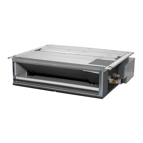
- Page 1 Installer reference guide Split system air conditioners FDXM25F3V1B FDXM35F3V1B Installer reference guide FDXM50F3V1B English Split system air conditioners FDXM60F3V1B...
- Page 2 3P480520-6A...
-
Page 3: Table Of Contents
Table of Contents 9 Hand-over to the user Table of Contents 10 Disposal 11 Technical data 1 General safety precautions 11.1 Wiring diagram ................17 About the documentation ............1.1.1 Meaning of warnings and symbols......For the installer................General safety precautions 1.2.1 General ............... -
Page 4: For The Installer
(on top of the instructions described in the Daikin documentation). ▪ In places where there is a risk of fire due to the leakage of flammable gases (example: thinner or gasoline), carbon fibre, CAUTION ignitable dust. -
Page 5: Brine
1 General safety precautions WARNING WARNING Always recover the refrigerant. Do NOT release them Take sufficient precautions in case of brine leakage. If directly into the environment. Use a vacuum pump to brine leaks, ventilate the area immediately and contact evacuate the installation. -
Page 6: About The Documentation
Daikin website (publicly accessible). exerted on the terminal board. ▪ The full set of latest technical data is available on the Daikin ▪ Use an appropriate screwdriver for tightening the extranet (authentication required). -
Page 7: To Remove The Accessories From The Indoor Unit
4 About the units and options Lift the unit by holding on to the hanger brackets without exerting System layout any pressure on other parts, especially on refrigerant piping, drain piping and other resin parts. 3.2.2 To remove the accessories from the indoor unit 1×... -
Page 8: Installation Site Requirements Of The Indoor Unit
5 Preparation ▪ Protective guards. Make sure to install protective guards on the WARNING suction and discharge side to prevent somebody from touching Do NOT install the air conditioner at any place where the fan blades or heat exchanger. flammable gas may leak out. If the gas leaks out and stays Do NOT install the unit in the following places: around the air conditioner, a fire may break out. -
Page 9: Refrigerant Piping Insulation
6 Installation Model L1 Liquid piping L1 gas piping Installation FDXM25+35 Ø6.4 Ø9.5 FDXM50+60 Ø6.4 Ø12.7 Overview: Installation 5.3.2 Refrigerant piping insulation This chapter describes what you have to do and know on-site to install the system. ▪ Use polyethylene foam as insulation material: Typical workflow ▪... -
Page 10: Guidelines When Installing The Ducting
6 Installation 4× Air inlet Air outlet Suction cover 5 Attach the air filter (accessory) by pushing down the hooks (2 hooks for 25+35 type, 3 hooks for 50+60 type). rear suction bottom suction Class A (mm) B (mm) FDXM25+35 FDXM50+60 1140 1190 Nut (field supply) Double nut (field supply) -
Page 11: Guidelines When Installing The Drain Piping
6 Installation Insulation piece (drain pipe) (accessory) ▪ Air leaks. Wind aluminium tape around the intake side flange and Drain piping (field supply) duct connection. Make sure there are no air leaks at any other connection. NOTICE ▪ Insulation. Insulate the duct to prevent condensation from ▪... -
Page 12: Precautions When Connecting The Refrigerant Piping
6 Installation ▪ Keeping in mind the guidelines for: 6.3.3 Guidelines when connecting the refrigerant piping ▪ Pipe bending ▪ Flaring pipe ends Take the following guidelines into account when connecting pipes: ▪ Brazing ▪ Coat the flare inner surface with ether oil or ester oil when connecting a flare nut. -
Page 13: To Braze The Pipe End
6 Installation Flare tool for Conventional flare tool R410A or R32 Clutch type Wing nut type (clutch type) (Ridgid-type) (Imperial-type) 0~0.5 mm 1.0~1.5 mm 1.5~2.0 mm 5 Check that the flaring is properly made. Gas piping Liquid piping Flare’s inner surface must be flawless. The pipe end must be evenly flared in a perfect circle. -
Page 14: To Connect The Electrical Wiring On The Indoor Unit
6 Installation Sealing material (accessory) ▪ If stranded conductor wires are being used, install a round crimp- Opening for cables style terminal on the tip. Place the round crimp-style terminal on Wire the wire up to the covered part and fasten the terminal with the 2 User interface cable: Route the cable through the frame, appropriate tool. -
Page 15: Specifications Of Standard Wiring Components
7 Configuration 6.4.5 Specifications of standard wiring The fuses or locally installed protection devices are installed according to this document, and have not been components bypassed. Component Specification The power supply voltage matches the voltage on the identification label of the unit. Interconnection cable Minimum cable section of (indoor↔outdoor) -
Page 16: Error Codes When Performing A Test Run
▪ A subset of the latest technical data is available on the regional operation, and the home Daikin website (publicly accessible). menu is displayed. ▪ The full set of latest technical data is available on the Daikin extranet (authentication required). Error codes when performing a test run... -
Page 17: Wiring Diagram
11 Technical data 11.1 Wiring diagram Unified Wiring Diagram Legend For applied parts and numbering refer to the wiring diagram sticker supplied on the unit. Part numbering is realized by Arabic numbers in ascending order for each part and is represented in the overview below by symbol “*” in the part code. CIRCUIT BREAKER PROTECTIVE EARTH CONNECTION... - Page 20 4P482333-1 2017.03...
Need help?
Do you have a question about the FDXM25F3V1B and is the answer not in the manual?
Questions and answers