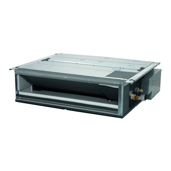
Daikin FDXM25F3V1B9 Installation Manual
Split system air conditioners
Hide thumbs
Also See for FDXM25F3V1B9:
- User reference manual (12 pages) ,
- Installer's reference manual (20 pages)
Summary of Contents for Daikin FDXM25F3V1B9
- Page 1 Installation manual Split system air conditioners FDXM25F3V1B FDXM35F3V1B FDXM50F3V1B FDXM60F3V1B FDXM25F3V1B9 FDXM35F3V1B9 Installation manual FDXM50F3V1B9 English Split system air conditioners FDXM60F3V1B9...
- Page 2 3P480520-6A...
- Page 3 3P480520-10B...
-
Page 4: Table Of Contents
▪ A subset of the latest technical data is available on the regional System layout................Daikin website (publicly accessible). 4 Preparation ▪ The full set of latest technical data is available on the Daikin extranet (authentication required). Preparing the installation site ............ 4.1.1 Installation site requirements of the indoor unit .. -
Page 5: About The Units And Options
3 About the units and options About the units and options System layout ≥300 ≥20 ≥400 (mm) Minimum distance to the floor: 2.7 m to avoid accidental touching. 2.5 m in case the fan is covered (e.g. false ceiling, grille, …) Control box Maintenance space Ceiling Floor surface... -
Page 6: Guidelines When Installing The Ducting
5 Installation 4× Air inlet Air outlet Suction cover 5 Attach the air filter (accessory) by pushing down the hooks (2 hooks for 25+35 type, 3 hooks for 50+60 type). rear suction bottom suction Class A (mm) B (mm) FDXM25+35 FDXM50+60 1140 1190 Nut (field supply) Double nut (field supply) -
Page 7: Guidelines When Installing The Drain Piping
5 Installation The ducting is to be field supplied. 5 Wind the large sealing pad (= insulation) around the metal clamp and drain hose, and fix it with cable ties. ▪ Air inlet side. Attach the duct and intake-side flange (field supply). -
Page 8: Connecting The Refrigerant Piping
5 Installation Bucket NOTICE Refrigerant pipes Drain outlet Make sure to use a recommended bubble test solution from your wholesaler. Do not use soap water, which may cause cracking of flare nuts (soap water may contain salt, Connecting the refrigerant piping which absorbs moisture that will freeze when the piping gets cold), and/or lead to corrosion of flared joints (soap DANGER: RISK OF BURNING... -
Page 9: Specifications Of Standard Wiring Components
6 Commissioning 4 Wrap the cables with the sealing material (accessory) to Checklist before commissioning prevent water from entering the unit. Seal all gaps to prevent small animals from entering the system. After the installation of the unit, first check the following items. Once all below checks are fulfilled, the unit MUST be closed, ONLY then WARNING can the unit be powered up. -
Page 10: Error Codes When Performing A Test Run
▪ A subset of the latest technical data is available on the regional Select Test Operation. Service Settings Daikin website (publicly accessible). Test Operation Maintenance Contact Field Settings ▪ The full set of latest technical data is available on the Daikin Demand extranet (authentication required). Min Setpoints Differential Group Address Return Setting Press. -
Page 11: Wiring Diagram
8 Technical data Wiring diagram Unified Wiring Diagram Legend For applied parts and numbering, refer to the wiring diagram on the unit. Part numbering is by Arabic numbers in ascending order for each part and is represented in the overview below by symbol “*” in the part code. CIRCUIT BREAKER PROTECTIVE EARTH CONNECTION... - Page 12 4P472267-1B 2018.07...


Need help?
Do you have a question about the FDXM25F3V1B9 and is the answer not in the manual?
Questions and answers