
Related Manuals for Emerson Bettis G2XXX M11 series


Summary of Contents for Emerson Bettis G2XXX M11 series
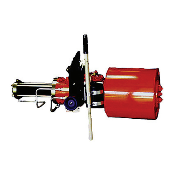
- Page 1 Service Instructions 124843E Rev. C August 2015 G01 through G10 Double-Acting Pneumatic Actuators with M11 Hydraulic Override...
-
Page 3: Table Of Contents
Service Instructions Table of Contents 124843E Rev. C August 2015 Table of Contents Section 1: Introduction General Service Information ..............1 Definitions ....................2 General Safety Information ................ 2 Bettis Reference Materials ................2 Service Support Items ................3 Lubrication and Fluid Requirements ............3 General Tool Information ................ - Page 4 Table of Contents Service Instructions August 2015 124843E Rev. C Section 6: Actuator Support Information M11 Hydraulic Override System Fluid Volume ........... 33 Module Weights by Item Number and Actuator Housing Size ....33 G01 Tool Style and Wrench Size ..............34 G2 Tool Style and Wrench Size ..............
-
Page 5: Section 1: Introduction
Service Instructions Section 1: Introduction 124843E Rev. C August 2015 Section 1: Introduction 1�1 General Service Information 1.1.1 This service procedure is offered as a guide to enable general maintenance to be performed on Bettis™ G01XXX-M11, G2XXX M11, G3XXX M11, G4XXX M11, G5XXX M11, G7XXX M11, G8XXX M11, and G10XXX M11 Double-Acting G-Series Actuators with one Pneumatic Power Module and one M11 or M11 S Hydraulic Override Module. -
Page 6: Definitions
Section 1: Introduction Service Instructions August 2015 124843E Rev. C 1�2 Definitions WARNING: If not observed, user incurs a high risk of severe damage to actuator and/or fatal injury to personnel. CAUTION: If not observed, user may incur damage to actuator and/or injury to personnel. NOTE: Advisory and information comments provided to assist maintenance personnel to carry out maintenance procedures. -
Page 7: Bettis Reference Materials
M11-S Manual Hydraulic Override System operating instructions part number 121962 with M11-S Assembly Drawing part number 121090. NOTE: If you require a specific assembly drawing (IE: GXX-M3 OR HYD) please contact Emerson Actuation Technologies Bettis by phone or email at info.actuationtechnologies@emerson.com 1�5 Service Support Items 1.5.1... -
Page 8: General Tool Information
Section 1: Introduction Service Instructions August 2015 124843E Rev. C 1�7 General Tool Information 1.7.1 Tools: All tools/Hexagons are American Standard inch. Large adjustable wrench, two (2) large screwdrivers, Allen wrench set, set of open/box end wrenches, rubber or leather mallet, torque wrench (up to 1200 foot pounds / 1627 N-m), breaker bar, small drift punch and a drive socket set. -
Page 9: Actuator Operation
Service Instructions Section 1: Introduction 124843E Rev. C August 2015 No tubing damaged or accessories dislodged during the shipping or the installation. Indicated position confirms valve position. All switching valves in normal operating position as per SCHEMATIC / INSTRUCTIONS 1.10.2 Check Connections Pneumatic / hydraulic components connected as per schematic enclosed in service manual supplied. -
Page 10: Section 2: Actuator Disassembly
Section 2: Actuator Disassembly Service Instructions August 2015 124843E Rev. C Section 2: Actuator Disassembly 2�1 General Disassembly WARNING: DANGEROUS GAS AND/OR LIQUIDS It is possible, that the actuator may contain a dangerous gas and/or liquids. Ensure that all proper measures have been taken to prevent exposure or release of these types of contaminants before commencing any work. - Page 11 Service Instructions Section 2: Actuator Disassembly 124843E Rev. C August 2015 CAUTION: DO NOT DAMAGE O-RING GROOVE Do not damage O-ring groove when removing end cap. 2.2.4 The fit between cylinder (3-70) and outer end cap (3-80) is very tight. Break end cap free by tapping with a breaker bar on lip provided on the end cap.
- Page 12 Section 2: Actuator Disassembly Service Instructions August 2015 124843E Rev. C 2.2.7 Remove piston as follows: (On early G2 and G3 models equipped with outboard and inboard tie bar nuts skip this step and go to step 2.2.9). 2.2.7.1 Refer to assembly drawing page 2 of 2 Detail "D". Remove two split ring halves (3-50) and one retainer ring (3-60) from outboard side of piston (3-30).
-
Page 13: Drive Module Disassembly
Service Instructions Section 2: Actuator Disassembly 124843E Rev. C August 2015 2�3 Drive Module Disassembly NOTE: Review Section 2 steps 2.1.1 through 2.1.3 General Disassembly before proceeding with drive module disassembly. 2.3.1 If not already removed remove piston rod (3-40) from drive module. 2.3.2 Mark stop screws (1-180) left and right. - Page 14 Section 2: Actuator Disassembly Service Instructions August 2015 124843E Rev. C NOTE: G01, G2, G3 and G4 model housing cover will have cast tabs for placing prying tools to aid in cover removal. 2.3.13 Remove housing cover (1-20) from housing (1-10). NOTE: Groove pins (1-130) will remain in housing cover (1-20) when housing cover is removed from housing (1-10).
-
Page 15: M11 Hydraulic Override Cylinder Disassembly
Service Instructions Section 2: Actuator Disassembly 124843E Rev. C August 2015 2.3.28 Housing (1-10) vent check assembly removal as follows: 2.3.28.1 G01, G2 and G3 housing (1-10) unscrew and remove one vent check assembly (13) from the front of housing (1-10). 2.3.28.2 G4 through G10 housing (1-10) unscrew and remove two vent check assemblies (13) from the front of housing (1-10). - Page 16 Section 2: Actuator Disassembly Service Instructions August 2015 124843E Rev. C 2.4.13 Remove hex cap screws (7-115) with lockwashers (7-110) from inner end cap (7-10). 2.4.14 Remove hex nuts (7-105) from hex cap screws (7-100). 2.4.15 Remove hex cap screws (7-100) with lockwashers (7-110) from inner end cap (7- 10) and housing (1-10).
-
Page 17: Section 3: Actuator Reassembly
Service Instructions Section 3: Actuator Reassembly 124843E Rev. C August 2015 Section 3: Actuator Reassembly 3�1 General Reassembly CAUTION: CHECK SHELF LIFE OF SEALS Only new seals, which are still within the seal’s expectant shelf life, should be installed into the actuator being refurbished. 3.1.1 Remove and discard all old seals and gaskets. - Page 18 Section 3: Actuator Reassembly Service Instructions August 2015 124843E Rev. C 3.2.1 If guide bar bearings are being replaced install new bearings into guide block (1-30). NOTE: The guide bar bearing must be pressed into guide block guide bar bore with the seam located ±5 degrees of the top or bottom centerline as shown in Section A-A.
- Page 19 Service Instructions Section 3: Actuator Reassembly 124843E Rev. C August 2015 NOTE: The spherical side of the washer will go on the extension rod assembly facing the head of the extension rod assembly. 3.2.11 Install extension rod assembly (9-50) into guide block (1-30) and up against the first spherical washer (9-40).
- Page 20 Section 3: Actuator Reassembly Service Instructions August 2015 124843E Rev. C NOTE: The yoke pin can be held in place by installing a screw into the .375-16UNC tapped hole in the upper end of yoke pin (1-80). 3.2.21 Install yoke pin (1-80) by inserting into the upper yoke arm, upper yoke/guide block bushing, guide block, lower yoke/guide block bushing, lower yoke arm and resting on lower yoke pin thrust bearing (2-10).
- Page 21 Service Instructions Section 3: Actuator Reassembly 124843E Rev. C August 2015 Table 2� Housing Cover Screw Quantity and Torque TORQUE (±5%) TORQUE (±5%) Model Model Lbf-ft� Lbf-ft� NOTE: Complete step 3.2.32 on G5, through G10 model actuators. For G01 through G4 model actuators skip step 3.2.32 and proceed to step 3.2.33.
-
Page 22: Pneumatic Power Module Reassembly
Section 3: Actuator Reassembly Service Instructions August 2015 124843E Rev. C 3.2.42 NOTE: Refer to Section 2 step 2.3.3 for correct position indicator placement. Install position indicator (1-220) over the exposed shaft of position indicator assembly (1-140). 3.2.43 Install stop screw nuts (1-190) onto stop screws (1-180). 3.2.44 Install O-ring (2-90) onto stop screws (1-180). - Page 23 Service Instructions Section 3: Actuator Reassembly 124843E Rev. C August 2015 3.3.6 Install one o-ring seal (4-90) into seal groove located on the inboard face of inner end cap (3-10). 3.3.7 Install inner end cap (3-10) on to housing (1-10). NOTE: The pressure inlet port should be positioned in the same position as recorded in section 2.2 step 2.2.1.
- Page 24 Section 3: Actuator Reassembly Service Instructions August 2015 124843E Rev. C 3.3.19 Apply lubricant to one O-ring seal (4-40) and install into the outer diameter O-ring groove of outer end cap (3-80). 3.3.20 Apply lubricant to the bore of cylinder (3-70). CAUTION: CAREFULLY INSTALL CYLINDER If needed, when installing the cylinder, hammer on the end of the cylinder only with a non metallic object.
-
Page 25: G2 And G3 Early Model Pneumatic Power Module Reassembly
Service Instructions Section 3: Actuator Reassembly 124843E Rev. C August 2015 3�4 G2 and G3 Early Model Pneumatic Power Module Reassembly NOTES: Early G2 and G3 pneumatic power modules where equipped with tie bars that had nuts on both ends of the tie bars (3-20) – double nuts. Refer to Section 2 step 2.1.4 for the correct installation location for piston rod (3-40). - Page 26 Section 3: Actuator Reassembly Service Instructions August 2015 124843E Rev. C 3.4.5.4 If the back-up rings are too long and the rings overlap beyond the skive-cuts, then the rings must be trimmed with a razor sharp instrument. 3.4.6 Coat one D-ring seal (4-60) with lubricant and install into the piston external seal groove. NOTE: The flat side of the D-ring seal goes down into the seal groove.
-
Page 27: M11 Hydraulic Override Cylinder Reassembly
Service Instructions Section 3: Actuator Reassembly 124843E Rev. C August 2015 3.4.17 Install lubricated cylinder (3-70) over piston (3-30) and onto inner end cap (3-10). When installing the cylinder over the piston seal tilt cylinder 15° to 30° degrees to piston rod. 3.4.18 Install outer end cap (3-80) over tie bars (3-20) and into cylinder (3-70). - Page 28 Section 3: Actuator Reassembly Service Instructions August 2015 124843E Rev. C 3.5.9 Coat one piston seal (8-60) with fluid and install into the piston external seal groove. CAUTION: INSTALL PISTON SEAL CORRECTLY Install the piston seal with energizer ring facing outside edge of piston (7-30). 3.5.10 Push the piston through the cylinder (7-70) until the outboard piston seal groove is exposed.
-
Page 29: Actuator Testing
Service Instructions Section 3: Actuator Reassembly 124843E Rev. C August 2015 CAUTION: INSTALL TIE BARS CORRECTLY Assemble tie bars (7-20) into inner end cap (7-10) a minimum engagement of one tie bar thread diameter. Insure that three to four threads are equally exposed beyond the tie bar nuts (7-90) at the outer end cap (7-80). - Page 30 PED by pressuring both sides of the piston to avoid damage and over torquing of the actuator components. If further future testing in the field is necessary, Emerson should be contacted for guidance. Actuator Reassembly...
-
Page 31: Section 4: Field Conversions
Service Instructions Section 4: Field Conversions 124843E Rev. C August 2015 Section 4: Field Conversions 4�1 Construction Reversal (Exchange Module Locations) 4.1.1 Remove pneumatic power module per Section 5.1. 4.1.2 Remove M11 hydraulic override cylinder per Section 5.3. 4.1.3 Using Section 5.1 reinstall the pneumatic power module onto the opposite end of housing (1-10) as it was previously located. -
Page 32: Section 5: Module Removal And Installation
Section 5: Module Removal and Installation Service Instructions August 2015 124843E Rev. C Section 5: Module Removal and Installation 5�1 Pneumatic Power Module Removal CAUTION: USE HEAVY DUTY SUPPORT EQUIPMENT Due to the weight and size of power module, heavy duty support equipment will be required when removing power module from the actuator housing. -
Page 33: M11 Hydraulic Overrides Cylinder Removal
Service Instructions Section 5: Module Removal and Installation 124843E Rev. C August 2015 WARNING: DO NOT CROSS-THREAD PISTON ROD When screwing piston rod into guide block (3-30) make certain that the piston rod and guide block threads do not cross-thread. 5.2.4 G2 THROUGH G10 MODEL ACTUATORS: 5.2.4.1 Align piston rod (3-40) with extension rod assembly (1-50). -
Page 34: M11 Hydraulic Override Cylinder Installation
Section 5: Module Removal and Installation Service Instructions August 2015 124843E Rev. C 5�4 M11 Hydraulic Override Cylinder Installation NOTE: Review Section 3.1 General Reassembly before proceeding with M11 Hydraulic Override Cylinder installation. 5.4.1 Check to verify that O-ring seal (4-90) is properly seated in its seal groove located on the housing side of inner end cap (7-10). -
Page 35: Powr Swivl Module Removal
Service Instructions Section 5: Module Removal and Installation 124843E Rev. C August 2015 5.4.10 Install and tighten hex nuts (7-105) onto hex cap screws (7-100). 5.4.11 Using pipe dope, install standard NPT pipe plug (7-120) into outer end cap (7-80). If the actuator uses SAE threads install SAE O-ring plug (7-120) into outer end cap (7-80). - Page 36 Section 5: Module Removal and Installation Service Instructions August 2015 124843E Rev. C 5.6.1 Push the guide block to the required side of the housing (1-10). NOTE: The guide block can be moved by inserting a long rod through either end of the housing and pushing on the guide block.
-
Page 37: Section 6: Actuator Support Information
Service Instructions Section 6: Actuator Support Information 124843E Rev. C August 2015 Section 6: Actuator Support Information 6�1 M11 Hydraulic Override System Fluid Volume Table 6� M11 Hydraulic Override System Fluid Volume ACTUATOR SIZE Quarts 1.0 10.2 16.6 34.5 APPROX VOLUME FLUID FOR M11 SYSTEM Liters 0.95... -
Page 38: G01 Tool Style And Wrench Size
Section 6: Actuator Support Information Service Instructions August 2015 124843E Rev. C ITEM MODULE NO� WT� WT� WT� WT� WT� WT� WT� WT� DESCRIPTION Lbs. 48” Dia. Power Lbs. 52” Dia. Power Lbs. 2.2” Dia. H Power Module 12.2 Lbs. 2.5”... -
Page 39: G2 Tool Style And Wrench Size
Service Instructions Section 6: Actuator Support Information 124843E Rev. C August 2015 6�4 G2 Tool Style and Wrench Size Table 9� G2 Tool Style and Wrench Size ITEM WRENCH ITEM LOCATION OR RECOMMENDED NO� SIZE DESCRIPTION TOOL STYLE 1-110 9/16” Hex Cap Screws Socket 1-160... -
Page 40: G4 Tool Style And Wrench Size
Section 6: Actuator Support Information Service Instructions August 2015 124843E Rev. C 6�6 G4 Tool Style and Wrench Size Table 11� G4 Tool Style and Wrench Size ITEM WRENCH ITEM LOCATION OR RECOMMENDED NO� SIZE DESCRIPTION TOOL STYLE 1-110 9/16” Hex Cap Screws Socket 1-160... -
Page 41: G7 Tool Style And Wrench Size
Service Instructions Section 6: Actuator Support Information 124843E Rev. C August 2015 6�8 G7 Tool Style and Wrench Size Table 13� G7 Tool Style and Wrench Size ITEM WRENCH ITEM LOCATION OR RECOMMENDED NO� SIZE DESCRIPTION TOOL STYLE 1-110 3/4” Hex Cap Screws Socket 1-120... -
Page 42: G10 Tool Style And Wrench Size
Section 6: Actuator Support Information Service Instructions August 2015 124843E Rev. C 6�10 G10 Tool Style and Wrench Size Table 15� G10 Tool Style and Wrench Size ITEM WRENCH ITEM LOCATION OR RECOMMENDED NO� SIZE DESCRIPTION TOOL STYLE 1-110 3/4” Hex Cap Screws Socket 1-120... -
Page 43: Section 7: Troubleshooting
In the unlikely event of a fault developing, the following Fault Location Table is provided to assist the service engineer to perform troubleshooting. This table is designed to cover as wide a range of Emerson Bettis actuators as possible. Reference to equipment not sup- plied should be ignored. -
Page 44: Operational Test
Section 7: Troubleshooting Service Instructions August 2015 124843E Rev. C 7�2 Operational Test 7.2.1 Full Stroke Test The “Full Stroke Test” (“On-line”) must be performed to satisfy the PFD (average probability of failure on demand) value. The full stroke test frequencies will be defined by the final installer to achieve the defined SIL level. -
Page 45: Section 8: Removal And Decommissioning
If a conflict arises between this procedure and the customer's pro- cedures, the differences should be resolved in writing between an authorized customer’s representative and an authorized Emerson/Bettis representative. CAUTION: ISOLATE AND POWER OFF ACTUATOR Make sure actuator is isolated before removing from valve. Turn OFF the power medium and bleed off all pressure first, including storage tank (if present). -
Page 46: Section 9: Document Revision
Service Instructions Section 9: Document Revision August 2015 124843E Rev. C Section 9: Document Revision Table 17� Revision Overview DATE BY * DATE Released Jan. 2002 B.Cornelius Jan. 2002 19110 July 2006 UPDATED C. Ross July 2006 VAWCO2750 Aug. 2015 UPDATED C. -
Page 47: Appendix A: List Of Tables
Service Instructions Appendix 124843E Rev. C August 2015 Appendix A: List of Tables Table 1. G-Series Models ....................3 Table 2. Housing Cover Screw Quantity and Torque ............17 Table 3. Piston Rod Torque Information ................. 18 Table 4. Tie Bar Nuts ..................... 20 Table 5. -
Page 48: Appendix B: List Of Drawings
Appendix Service Instructions August 2015 124843E Rev. C Appendix B: List of Drawings B�1 Part No� 115680, GXXXX-H Pneumatic Assembly Drawing, Sheet 1 of 2 Appendix... - Page 49 Service Instructions Appendix 124843E Rev. C August 2015 B�2 Part No� 115680, GXXXX-H Pneumatic Assembly Drawing, Sheet 2 of 2 Appendix...
- Page 50 Appendix Service Instructions August 2015 124843E Rev. C B�3 Part No� 126567, M11 Assembly Drawing, Sheet 1 of 5 Appendix...
- Page 51 Service Instructions Appendix 124843E Rev. C August 2015 B�4 Part No� 126567, M11 Assembly Drawing, Sheet 2 of 5 Appendix...
- Page 52 Appendix Service Instructions August 2015 124843E Rev. C B�5 Part No� 126567, M11 Assembly Drawing, Sheet 3 of 5 Appendix...
- Page 53 Service Instructions Appendix 124843E Rev. C August 2015 B�6 Part No� 126567, M11 Assembly Drawing, Sheet 4 of 5 Appendix...
- Page 54 Appendix Service Instructions August 2015 124843E Rev. C B�7 Part No� 126567, M11 Assembly Drawing, Sheet 5 of 5 Appendix...
- Page 55 Service Instructions Appendix 124843E Rev. C August 2015 B�8 Part No� 121090, M11D-S Assembly Drawing, Sheet 1 of 3 Appendix...
- Page 56 Appendix Service Instructions August 2015 124843E Rev. C B�9 Part No� 121090, M11D-S Assembly Drawing, Sheet 2 of 3 Appendix...
- Page 57 Service Instructions Appendix 124843E Rev. C August 2015 B�10 Part No� 121090, M11D-S Assembly Drawing, Sheet 3 of 3 Appendix...
- Page 58 Appendix Service Instructions August 2015 124843E Rev. C B�11 Part No� 121107, M11S Remote Mount Assembly Drawing, Sheet 1 of 2 Appendix...
- Page 59 Service Instructions Appendix 124843E Rev. C August 2015 B�12 Part No� 121107, M11S Remote Mount Assembly Drawing, Sheet 2 of 2 Appendix...
- Page 61 ©2017 Emerson. All rights reserved. No. 1 Lai Yuan Road EUROPE Wuqing Development Area The Emerson logo is a trademark and service mark of Emerson Electric Co. Tianjin 301700 Berenyi u. 72- 100 Bettis is a mark of one of the Emerson family of companies.
Need help?
Do you have a question about the Bettis G2XXX M11 series and is the answer not in the manual?
Questions and answers
can we use M11 instead of M18