Table of Contents
Advertisement
Advertisement
Table of Contents

Subscribe to Our Youtube Channel
Related Manuals for Alcatel 9400 UX


Summary of Contents for Alcatel 9400 UX
- Page 1 Alcatel 9400 UX User Manual 3CC08991ATAA TQBJA 01...
- Page 2 Released Change Note Short Title Alcatel 9400UX All rights reserved. Passing on and copying of this document, use and communication of its contents not permitted without written authorization from Alcatel. Issue 01 -- March 2004 3CC08991ATAA TQ BJA 01 2/314...
- Page 3 1 1 1 1 3 3 3 3 , , , , 1 1 1 1 5 5 5 5 , , , , 1 1 1 1 8 8 8 8 , , , , 2 2 2 2 3 3 3 3 , , , , 2 2 2 2 5 5 5 5 o o o o r r r r 3 3 3 3 8 8 8 8 G G G G H H H H z z z z S S S S m m m m a a a a l l l l l l l l a a a a n n n n d d d d M M M M e e e e d d d d i i i i u u u u m m m m C C C C a a a a p p p p a a a a c c c c i i i i t t t t y y y y D D D D i i i i g g g g i i i i t t t t a a a a l l l l M M M M i i i i c c c c r r r r o o o o w w w w a a a a v v v v e e e e L L L L i i i i n n n n k w w w w i i i i t t t t h h h h s s s s u u u u p p p p e e e e r r r r v v v v i i i i s s s s i i i i o o o o n n n n...
- Page 4 PAGE INTENTIONALLY LEFT BLANK Issue 01 -- March 2004 3CC08991ATAA TQ BJA 01 4/314...
- Page 5 Congratulations on having bought your equipment from Alcatel. We hope that it will give you full satisfaction. For any additional information, about your Alcatel Welcome Center (for Technical Support or for repair process), please contact your Accatel Contract Manager. 3CC08991ATAA TQ BJA 01...
- Page 6 PAGE INTENTIONALLY LEFT BLANK Issue 01 -- March 2004 3CC08991ATAA TQ BJA 01 6/314...
-
Page 7: Table Of Contents
............2.1.3 -- ALCATEL 9400 UX features . - Page 8 ........... 4.2 -- 9400 UX applications .
- Page 9 4.5 -- “Operation parameters” application ..........4.5.1 -- “Terminal”...
- Page 10 ............6.1.1 -- Network supervised with the Alcatel network management system .
- Page 11 7 - - Changing configurations ............7.1 -- Changing frequency .
- Page 12 7.15 -- Replacing consumable items ........... 7.15.1 -- MCU board battery .
- Page 13 Appendix 9 - - List of RTP application alarms ..........Appendix 10 - - Creating user profiles .
- Page 14 PAGE INTENTIONALLY LEFT BLANK Issue 01 -- March 2004 3CC08991ATAA TQ BJA 01 14/314...
-
Page 15: Foreword
1 - - Foreword Structure of the manual This manual is for users with a sound knowledge of how to operate and install microwave links and how to use a PC-based craft terminal running the Windowst operating system. With it, you should quickly be able to operate the equipment. -
Page 16: Safety Instructions
If necessary, return the equipment to Alcatel After Sales for service and repair. DO NOT substitute parts or modify equipment: Return the product to Alcatel Customer Service for servicing and repair. -
Page 17: Symbols Used In The Document
1.3.2.2 - - Earth symbols Terminal for connecting the protective earth conductor in power supply wiring Other earth terminal 1.3.2.3 - - Other symbols Indicates compliance with European standards Emissions frequency: check that this complies with the standards in use in the country. Radiation alert 1.3.3 - - Symbols used in the document These symbols alert the reader the possible risks. -
Page 18: Certificate Of Compliance With European Safety Standards
1.3.4 - - Certificate of compliance with European safety standards Issue 01 -- March 2004 3CC08991ATAA TQ BJA 01 18/314... -
Page 19: Eco--Declaration
1.3.5 - - Eco- -Declaration 3CC08991ATAA TQ BJA 01 Issue 01 -- March 2004 19/314... -
Page 20: Public Exposition To Electromagnetic Fields
1.3.6 - - Public exposition to electromagnetic fields The public protection towards electromagnetic fields emitted by the antenna of the 9400UX is one of main requirements of the R&TTE Directive. An evaluation of the security measures to be implemented is presented in Appendix 1. -
Page 21: Description Of The Equipment
The Alcatel 9400 UX family covers the frequency range from 13 to 38 GHz, necessary to satisfy the largest range of propagation conditions as well as network configurations that gives also the ability to have a highest spectrum efficiency from 13 up to 38 GHz band with a 16QAM version. -
Page 22: Configuration
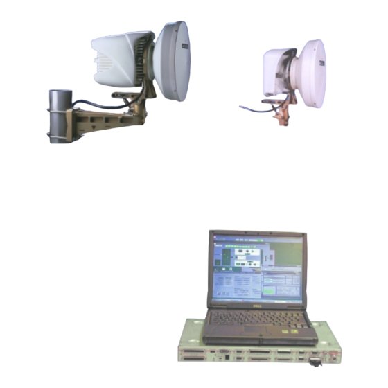
(*) Please consult factory if other Tx/Rx separations are requested. The Alcatel 9400 UX system features high spectrum efficiency (minimum use of RF bandwidth for a given capacity). The spectrum efficiency is optimized with the use of a 4 QAM or 16 QAM modulation (4 or 16 states Quadrature Amplitude Modulation) with digital filtering, providing compliance with the relevant ETSI spectrum masks and spurious emissions requirements (ERC Rec 74--01). - Page 23 1+0 9400 UX Outdoor Unit on its pole mounting, with New generation unit 9400UX flat ODU Main IDU and Equipment Craft Terminal 30 cm integrated antenna Figure 1 - Alcatel 9400 UX 1+0 configuration 2.1.2.2 - - Protected configuration Two types of problem can impact the availability of a radio link: equipment failures and propagation problems.
-
Page 24: Alcatel 9400 Ux Features
2.1.3.1 - - Equipment flexibility Software controlled frequency: The in--field agility of the 9400 UX is provided on a quarter frequency plan (synthesizer step 250 kHz). Only four different ODUs maximum are needed to cover the full frequency band. Figure 2 - Sub- band breakdown The synthesized , software controlled, RF local oscillator allows an easy frequency setting. - Page 25 1+0 configuration, it is common to 9400UX – from 13 to 38 GHz. The 9400 UX outdoor unit can be used with an integrated antenna 300 or 600 mm diameter or separate antennas if a larger diameter is needed.
- Page 26 The ODU is fixed by means of quick latches. This system allows to change the ODU without altering the antenna alignment. Two ODU generations are available. The new generation ODU, A9400 UX flat ODU, is lighter than the previous range from 94xxUXR201 to 94xxUXR203*. It is 4 and 16QAM compatible and software configurable only. * xx is for the band frequency of the Outdoor unit.
- Page 27 2.1.3.3 - - Equipment software features The Alcatel 9400 UX terminal provides a F interface to a Craft Terminal (PC), which enables alarm monitoring, quality measurement, as well as configuration of the equipment. The Alcatel 9400 UX Network Element (NE) supports a basic group of applications, listed hereafter, which provide simplified testing, operation and maintenance of the equipment: “Administrative Functions”:...
- Page 28 Remote Craft Terminal management (RCT): A remote mediation function can be activated on any Alcatel 9400 network element (slave configuration). From the CT connected to a remote network element, the operator gets the complete view of the network and is able to perform the same operations of supervision allowed from the craft terminal connected to the embedded mediation equipment (alarms, configurations).
-
Page 29: Capacity Configurations
2.1.4 - - Capacity configurations 2.1.4.1 - - Classic IDU version The capacity configurations depend: on the type of line interface units (LAU and LIU) installed in the IDU(s), the software key used. The table below summarizes the capabilities according to the bit rates supported by the IDU of the equipment and the type of software key used. -
Page 30: Operation
TS/TC back alarms (Supervision 3/4/5 bus) Equipment not included in the standard configuration Alcatel or but sold as options Customer Mediation device (RQ2) (SNMP) Figure 6 - Block diagram of a 1+ 0 station (classic IDU version) Issue 01 -- March 2004... - Page 31 Service kit (Supervision Functions set up in the bus) ESC3 MCU Light board Mediation Alcatel or device Customer Equipment not included in (RQ2) the standard configuration but sold as options (SNMP) Figure 7 - Block diagram of a 1+ 0 station (Light IDU versions) 2.2.1.1 - - Operation of the main IDU (InDoor Unit) (classic IDU version)
- Page 32 connection of local supervision system, for connecting a supervision PC; depending on the software versions, two types of SIMM memory are used: a basic version for 946LUX11 and 946LUX12 operating system versions (RQ 2) an extended version (option sold by reference 9400UXB267) for 946LUX40 software (SNMP) processing of external commands: telesignalling and remote controls (TS/TC), control of the outdoor unit, interfacing with the outdoor unit, for:...
- Page 33 2.2.1.3 - - IDU/ODU cable A coaxial cable, only available in 50 ohm impedance version, with a maximum length of 300 meters (when of standard type), connects the IDU to the ODU. This carries: the digital data streams between the IDU and the ODU, comprising: the aggregate obtained from tributary multiplexing, the ODU control signals, in the case of a classic IDU, the IDU/ODU telephone channel (connected to ESC N_2).
-
Page 34: Basic 1+1 Configuration
For the 13 GHz and the 23 to 38 GHz frequency bands, the transmitted power can be adjusted in 1 dB steps by software configuration (software key option needed), within a range of: --20 dB from nominal output power for 13 GHz (94xxUXR202 and 94xxUXR203), --30 dB from nominal output power for 15, 23, 25, 38 GHz (4QAM RTPC), --20 dB from nominal output power for 23, 25, 38 GHz (94xxUXR203 16QAM). - Page 35 One 2 Mbit/s aux. coupler bit stream Antenna (only at 34 Mbit/s) Software Back Service Tel. TS/TC alarms 3/4/5 back (Supervision bus) Alcatel or Mediation Customer device (SNMP) (RQ2) OUTDOOR Cable EXTENSION INDOOR UNIT UNIT coupler Antenna EOW3 EOW4 EOW5...
-
Page 36: 1+1 Configuration With Multiplexer/Demultiplexer Protection
UNIT Software Service Tel. Back to TS/TC Tributaries back alarms 3/4/5 1 to 16 (Supervision bus) One 2 Mbit/s Alcatel or auxiliary Mediation Customer bit stream device (only at (RQ2) (SNMP) 34 Mbit/s) OUTDOOR Cable coupler Tributaries EXTENSION INDOOR UNIT... - Page 37 (only at 34 Mbit/s) Software Service Back to TS/TC Tel. Tributaries 1 to 16 back alarms 3/4/5 (Supervision bus) One 2 Mbit/s aux Alcatel or bit stream Mediation Customer (only at 34 Mbit/s) device (RQ2) (SNMP) OUTDOOR Cable coupler Tributaries EXTENSION INDOOR UNIT UNIT 1 à...
-
Page 38: Engineering Service Channels
Engineering service channels The equipment comprises: in the classic IDU configuration: five engineering service channels (ESC N_1 to ESC N_5), except in the 2 x 2 Mbit/s configuration (only three ESC). in the Light IDU configuration: two engineering service channels (ESC N_1 and ESC N_3). In the main classic IDU and in the Light IDU, the characteristics of these engineering service channels are predefined. -
Page 39: Esc Number 1
As many configurations are possible, it is recommended to contact Alcatel for the network configuration. With integrated mediation (classic IDU configuration option), one of the stations in the network can be designated as a “master” station. It then supervises a network of up to 63 Alcatel 9400LX or UX network elements. -
Page 40: Esc Number 2
2.3.2 - - ESC number 2 Engineering service channel N_2 is a telephone channel with selective calling available only in the classic IDU version. The handset is connected to the connector on the main IDU. Each terminal is assigned a call number between 011 and 999 (not including X00) on installation. The number 00 is for general calling. -
Page 41: Esc Number 5
POINT-TO-MULTIPOINT ESC This type of ESC can be used only for asynchronous digital links. Connection for the ESC equipment: ESC N_3: to connectors “ESC 3-1” and “ESC3-2” of the extension IDU, ESC N_4: to connectors “ESC 4-1” and “ESC4-2” of the extension IDU. The connection of the terminals for ESC N_3 is illustrated in Figure 14. -
Page 42: Alarms, Telesignalling And Remote Controls (Ts/Tc)
Alarms, telesignalling and remote controls (TS/TC) The equipment has: Three loops, respectively preassigned for “Urgent alarm” (URG), “Non-urgent alarm” (NURG) and “Attended” (ATT) states. Each alarm or event generated by the equipment can be classified as Urgent, Not Urgent, Inhibited or Status by the supervisory software (§ 4.5.5). A remote control loop, available to the user. - Page 43 To antenna Aggregate IDU PRINCIPAL Tributaries 1+0 CONFIGURATION (classic IDU, Light IDU) To antenna Aggregate ODU 1 IDU PRINCIPAL Tributaries To antenna Aggregate ODU X EXTENSION IDU 1+1 HSB CONFIGURATION (classic IDU) To antenna Aggregate ODU 1 MAIN IDU To antenna Active MUX Aggregate Tributaries...
-
Page 44: Equipment Management
MAIN IDU MAIN IDU Remote ➣ BER analyzer loopback Local station Remote station Figure 17 - Checking a hop using the remote loop option The remote loop remote control function must be executed on the remote station. ➣ Remote loopback can be used in a station’s IDU to loop the receive output of a tributary to its transmit input. -
Page 45: Idu Controls, Indications And Connectors
IDU controls, indications and connectors The indoor units have a “Connector” panel and an “Operation” panel (Figure 18). The operation panel carries controls and indicators which duplicate those on the “Connector” side. The tables in the sections that follow describe these components. In some configurations, some of the items described below may be omitted. - Page 46 ITEM TYPE FUNCTION Female 2 Mbit/s port version: 37-way sub-D Tributaries 1 to 16. connectors I/O (1/8)* 34 Mbit/s port version: 2 Mbit/s auxiliary bit stream (connector on the LAU board). I/O (9-16)* 34 Mbit/s ports on 1.6/5.6 coaxial sockets mounted on a plate installed in place of the top “I/O (9/16)”...
-
Page 47: Light Idu
2.7.2 - - Light IDU 2.7.2.1 - - Light IDU (19” version) The Light IDU version has only a “Connector” panel (Figure 19) with: switches and a software reset button, display components for ascertaining the operational state of the equipment at a glance, connector ports. -
Page 48: Extension Idu
2.7.3 - - Extension IDU Extension IDU connector panel Extension IDU operation panel Figure 20 - Extension IDU controls, indicators and connectors The connector panel of the extension IDU is fitted with: indicators showing the operational status of the equipment at a glance, connectors. -
Page 49: Access Idu
ITEM TYPE FUNCTION Female X X X MAIN 68-way mini-D Link with the main IDU’s “EXT” connector. connector Female X X X ESC. 5 25-way sub-D Port for ESC N5. connector Female X X X BACK TO BACK 50-way mini-D Not used. - Page 50 The connector panel of the access indoor unit is fitted with the components described in the table below: ITEM TYPE FUNCTION I/O (1/8)* Female 2 Mbit/s access version: 37-way sub-D Tributaries 1 to 16. I/O (9/16)* connector 34 Mbit/s access version: 2 Mbit/s auxiliary bit stream port.
-
Page 51: Technical Characteristics
EN 300 197 38 GHz 37--39.5 ERC 12--01 1260 ITU--R Rec F749--1 16QAM (*) consult Alcatel if non--standard Tx/Rx separations are requested. (*) consult Alcatel for availability of these options RF CHANNELING Capacity (Mbit/s) 16x2 / 34+2 RF Channeling (MHz) (4QAM modulation) - Page 52 16QAM (*) xx is for the Outdoor IDU frequency band. For example, an IDU referenced 9413UX202 depends on the 13Ghz frequency band. (**) consult Alcatel for availability of these options Issue 01 -- March 2004 3CC08991ATAA TQ BJA 01 52/314...
- Page 53 TUNABILITY RANGE FOR NEW GENERATION ODU A9400UX flat ODU Duplex Frequency Output power difference agility band Equipment Output power setting (dB) (dBm) (MHZ) (MHz) 4 QAM + 24 +24 to –6 dBm with 1 dB step 9413 UX 16 QAM +20 to –10 dBm with 1 dB step 4 QAM...
- Page 54 BER THRESHOLDS FOR NEW GENERATION ODU A9400UX flat ODU* Equipment 16x2 / 34+2 –3 –6 –3 –6 –3 –6 –3 –6 4 QAM –95 –92 –92 –89 –89 –86 –86 –83 9413 UX 16 QAM – – – – –84 –81 –81 –78...
- Page 55 1+0/1+1 FD SYSTEM GAIN – AT ANTENNA PORT (INCLUDING DUPLEXER LOSS) FOR ODU UXR201, 94 UXR202 OR 94 UXR203 Equipment 16x2 / 34+2 9423 UX 16QAM – – – – 9425 UX 4QAM 9425 UX 16QAM – – – – 9438 UX 4QAM 9438 UX 16QAM –...
- Page 56 In the case of a 75 Ohms connection, the respect of the G703 norms and CEM norms is only guaranteed by ALCATEL if “spider” adaptaters are used 3CC07885Axxx or 3CC07759Axxx made for this purpose and with the IDU configuration.
- Page 57 ELECTROMAGNETIC COMPATIBILITY / SAFETY EN 301 489 1 & 4 (version 1.2.1) Safety EN 60 950 Power supply EN 300 132 Lightning protection Symmetric protection implemented in ODU & IDU +/-- 1kV on cable ground according to IEC 61000--4--5 with 2 wave types: 1.2/50 ←s and 10/700 ←s IDU- -ODU CABLE Type...
-
Page 58: Frequency Agility Bands
Frequency agility bands ALL VALUES EXPRESSED IN MHz FOR A 3.5 MHz CHANNEL. Equipment Duplex F min F max difference Band 9413 UX 1106 12751.75 12864.25 12861.75 12978.25 13017.75 13130.25 13127.75 13244.25 9415 UX 1260 14502.75 14723.50 14719.75 14940.25 14922.75 15143.25 15139.75 15360.25... - Page 59 Equipment Duplex F min F max difference Band 9418 UX 1180 18581.75 18698.25 18701.75 18818.25 18921.75 19038.25 19041.75 19158.25 1560 2235 17701.75 18138.25 19261.75 19698.25 1010 1850 17701.75 18199.25 18180.75 18678.25 18711.75 19210.25 19190.75 19698.25 1008 1848 17703.75 18199.25 18182.75 18678.25 18711.75 19207.25...
- Page 60 Equipment Duplex F min F max difference Band 9425 UX 1008 1848 24549.75 24996.25 24997.75 25444.25 25557.75 26004.25 26005.75 26452.25 9838 UX 1260 2100 37059.75 37616.25 37619.75 38176.25 38319.75 38876.25 38879.75 39436.25 Issue 01 -- March 2004 3CC08991ATAA TQ BJA 01 60/314...
-
Page 61: Installation
Unpack the equipment according to the instructions on the packaging. Take an inventory and identity any missing items. If the delivery does not match the delivery advice note, notify ALCATEL within 48 hours of receipt of the equipment. Leave the equipment readily accessible during the work. -
Page 62: Labels On The Equipment
Labels on the equipment The labels below are also affixed to the boxes to indicate their contents. LIGHT IDU LABEL INFORMATION 20 to 40 V= Power supply voltage 39 to 60 V = value Maximum IDU capacity 4x2 Mbit/s Floating power supply 2 Mbit/s tributary port 75 ohms or 120 ohms impedance... - Page 63 TYPICAL LABEL ON THE EXTENSION IDU * Reserved for Alcatel Power supply 20 to 40 V = voltage value 39 to 60 V = Maximum IDU 4x2 Mbit/s ; 8x2 Mbit/s capacity (according to 16x2 Mbit/s ; 34+2 Mbit/s equipment)
- Page 64 TYPICAL LABEL ON THE ODU 94 UXR201 94 UXR202 94 UXR203 Power supply voltage value Edition date Std = Standard Transmit power for 15 and 18 GHz High= High power YES + commerc. code; NO RF local loopback Duplex difference for transmission Min and maxi operating frequencies Canal...
- Page 65 SOFTWARE KEY LABEL ON THE BOX Integrated mediation function: Master or Slave + commercial code ALCATEL 9400 UX RCT (remote craft terminal) Y (yes) + commercial code or N (no) 1+0 max. or Max. configuration 1+1 max Max bit rate + commercial 2 x2 ;...
-
Page 66: Typical Installation Dimensions (1+0 Configuration With Integrated 1 Ft)
3.2.1 - - Typical installation dimensions ( 1+0 configuration with integrated 1 ft) 3.2.1.1 - - ODU 94xxUXR201 A 94xxUXR203 Pole mounting 1+1 Pole mounting 1+0 Issue 01 -- March 2004 3CC08991ATAA TQ BJA 01 66/314... - Page 67 3.2.1.2 - - ODU A9400 UX flat ODU Pole mounting 1+1 Pole mounting 1+0 3CC08991ATAA TQ BJA 01 Issue 01 -- March 2004 67/314...
-
Page 68: Installing The Equipment
3.3.3 - - Tools required The list of the tools required to install the microwave links of the 9400 UX family is given below (applies to all frequency bands). Tool Usage examples 2.5 mm Allen key (for M3 screw) -
Page 69: Fasten Torques For The Screws And Connectors
* It is also possible to order just the “service kit” cable, under reference 9400UXT112. A compass and a pair of binoculars (not supplied) are useful for roughly pointing the antenna. 3.3.4 - - Fasten torques for the screws and connectors The table below shows the maximum fasten torques requested. -
Page 70: Installation On Feet Or On A Wall Mounting
Useful cable way 27x210 3.4.2.2 - - Alcatel recommendations for IDU installation in 9U rack The recommendations depend on IDU configurations (1+ 0, 1+1 basic or 1+1 mux protected ) 1+1 mux protected configuration : each group of 2 or 3 IDU shall be separated by 1U. - Page 71 1+1 Mux protected 9 U rack 1+1 Mux protected 1+0 or 1+1 basic configuration 1+0 or 1+1 basic configuration 9 U rack 1+0 or 1+1 basic configuration 1+0 or 1+1 basic configuration Figure 22 - Example of installation in 9U Rack 3.4.2.3 - - Laborack installation Laborack dimensions :...
-
Page 72: Issue 01 -- March 2004 3Cc08991Ataa Tq Bja
3.4.2.4 - - Alcatel recommendations for IDU installation in rack The recommendations depend on IDU configurations (1+ 0, 1+1 basic or 1+1 mux protected ) 1+1 mux protected configuration : each group of 2 or 3 IDU shall be separated by 1U. -
Page 73: Outdoor Part Installation
Outdoor part installation 3.5.1 - - General information 3.5.1.1 - - Pole mounting The mechanical assembly is supplied complete, mechanically assembled, with screw fastenings kit and ground terminals included in a plastic bag inside the casting. The standard mechanical system is mounted on a pipe with a diameter of: 90 to 114 mm for 300 mm diameter antennas, 114 mm for 600 mm diameter integrated antennas. -
Page 74: Choosing Antenna Polarization
3.5.1.2 - - ODU 9400 UX Outdoor units are designed for assembly: either with an integrated antenna connected directly to the Outdoor equipment, see § 3.5.4.1 and 3.5.4.5, or with one or more non--integrated antennas, see § 3.5.5., mounted with flextwist guides. -
Page 75: Installing The Configuration With Pole Mounting 1 + 0 (9400Uxi102)
Vertical polarization Horizontal polarization ANTENNA - NOSE END VIEW Socket cap screw vertical polarization Nose O-ring seal TOP marker Socket cap screw “Antenna nose” slots Socket cap screw Drain orifice To change the polarization: undo the three socket cap screws and turn the nose through 90 degrees then tighten the screws again. - Page 76 Top marker Grower washer Flat washer Centering pin or screw M6 x 7 screws and “Ondulex” washer x 7 Casting ODU 94 UXR201,94 UXR202, UXR203 Optional kit: A9400UX FLAT ODU 9400UXI103 Figure 25 - Pole mounting 1+0 configuration ( 9400UXI102) CAUTION: For the fasten torques of the screws, refer to chapter 3.3.4.
- Page 77 Catch bead Support plate A Position of catch for F > 20 Position of catch for F < 20 GHz for from ODU from 94xxUXR201 to 94xxUXR203 94xxUXR201 to 94xxUXR203 Reposition the solar shield via the back of the ODU from 94xxUXR201 to 94xxUXR203, centre the bottom ribs of the solar shield in the “grooves”...
- Page 78 Catch bead Position of catch for Flat ODU A9400UX flat ODU Flange the ODU handle. Reposition the solar shield via the back of the flat ODU. Slide fully home, and moderately tighten by hand the screw (M4) on the ODU. CAUTION : When demounting, if the screws cannot be reached by hand, use a screw- driver.
-
Page 79: Pointing The Antenna
Note: Be aware that azimutal coarse pointing of antenna is done at this phase. 3.5.3.4 - - Coarse pointing the antenna Coarse pointing of the antenna is carried out as follows: Roughly adjust the elevation orientation of the “pole mounting” in the direction of the remote station. - Page 80 si - -5_<α<5_ Put the screws in the ∼ = 25 _ two external holes ∼ = 25 _ ∼ > 5 ∼ < - - 5 Put the screws in the 2 holes visible through the window, i.e. the middle and the external hole.
-
Page 81: Installing The Configuration With Pole Mounting 1 + 1 (9400Uxi101)
3.5.4 - - Installing the configuration with pole mounting 1 + 1 (9400UXI101) This assembly is valid only for antenna diameters of up to 600 mm (two feet). The antenna is screwed to the pole mounting 9400UXI101. The ODU is mounted with quick latches. Overall antenna steer (with turnbuckles set to the “maximum”) is: azimutal: 360 degrees for a 300 mm diameter antenna and 180 degrees for a 600 mm diameter antenna,... - Page 82 Top marker Centering pin 7 x M6 screw and or screw “Onduflex” washer A9400UX FLAT ODU UXR201, UXR202, Casting UXR203 Grower washer flat washer Optional kit 9400UXI103 CAUTION: For the fasten torques of the screws, refer to chapter 3.3.4. Figure 31 - 9400UXI101 configuration Issue 01 -- March 2004 3CC08991ATAA TQ BJA 01 82/314...
- Page 83 3.5.4.1 - - Installing the ODU 94 UXR201, 94 UXR202, 94 UXR203 Remove the solar shield by undoing the M6 fixing screw with a 16 mm flat wrench. Take the ODU by the handle, offer up the two protrusion bosses located inside the “nose” of the unit and facing the two grooves in the “nose”...
-
Page 84: Issue 01 -- March 2004 3Cc08991Ataa Tq Bja
Flange the ODU handle. Reposition the solar shield via the back of the flat ODU. Slide fully home, and moderately tighten by hand the screw (M4) on the ODU. CAUTION : When unscrewing, if the screws cannot be reached by hand, use a screw- driver. - Page 85 Position of pack of screw “Pole mounting” fasteners and terminals Azimuthal locking Kit 9400UXI103 screw (optional) Figure 32 - Pointing the antenna 4) Position the U bolts 2 on the pole, fit the flat washers, “grower” washers and nuts. CAUTION: For the fasten torques of the screws, refer to chapter 3.3.4. 3CC08991ATAA TQ BJA 01 Issue 01 -- March 2004 85/314...
- Page 86 3.5.4.5 - - Installing the (1+1) HSB configuration with integrated antenna TYPICAL 1 + 1 HSB CONFIGURATION WITH COUPLER -- ODU 94xxUXR201 to ODU 94xxUXR203 750 ( 13 38 GHz ) Coupler box Antenna Solar shield Main ODU Coupler Standby ODU Support (“Pole mounting”) -- ODU 9400UX flat ODU Solar shield...
-
Page 87: Installation With Non-Integrated Antenna
INSTALLING THE HSB COUPLER IMPORTANT NOTE: NEVER REMOVE THE ROUND YELLOW PADS THAT ARE USED TO SEAL THE OUTDOOR SYSTEM. The coupler is supplied with vertical polarization (see § 3.5.2). The procedure for changing the polarization of the HSB coupler is described in that section (see § 7.13). This must be done before installation. To install the HSB coupler assembly: take it by the handle, offer up the two bosses located in the “nose”... - Page 88 3.5.5.2 - - Typical installation a) with ODU 94xxUXR201 or 94xxUXR202 or 94xxUXR203 Smooth square flange Flextwist Square flange with groove ODU 94xxUXR201 or 94xxUXR202 or 94xxUXR203 Antenna 0.90 m or greater Adpater nose Support radio 94XXUXI102 b) with ODU 94xxUXR204 Flextwist ODU 9400UX flat ODU with solar shield...
- Page 89 3.5.5.3 - - Assembling and installing radio support For installation, you will need the following: The ODU support, ref: 1AB128510002 is regardless of frequency band. a microwave nose, a 600 mm long “flextwist” waveguide. Note : As our ODU supports are chromate plated or tinned on the “flextwist”, be careful with the materials used facing the unit to prevent any galvanic couple.
- Page 90 3.5.5.4 - - Installing the ODU 94xxUXR201, 94xxUXR202, 94xxUXR203 1) Remove the solar shield by undoing the M6 fixing screw with a 16 mm flat wrench. 2) Take the ODU by the handle, offer up the two bosses inside the “nose” of the unit to the two grooves in the “adapter nose”...
- Page 91 3.5.5.6 - - Installing the “Flextwist” waveguide Refer to the example given in § 3.5.5.2 and the table in § 3.5.5.3. This 600 mm long twistable flexible waveguide is supplied complete with gaskets and fasteners. At one end, it has a smooth square flange (to be mounted on the antenna) and at the other end, a grooved square flange designed to accommodate an O-ring seal (mounted at the ODU end).
-
Page 92: Wiring
Wiring 3.6.1 - - Wiring the power supply to the 19” indoor units 3.6.1.1 - - Direct connection with the power supply The 48 V DC or 24 V DC connection kit is for setting up the power connection between the main or extension IDU and the distribution panel (one for each terminal). -
Page 93: Equipment Earthing
For both these products, the fuses used are 8.5 x 31.5 6A 400V gG domestic type cartridges. The cables supplied to connect the IDUs are: 48 V: 3CC08165AAxx(3 x 1.5 mm 24 V: 3CC08209AAxx (3 x 2.5 mm To connect the “operator’s” input, the recommended cable is: 48 V : 3CC08211AAxx (3 x 4 mm 24 V : 3CC08212AAxx (3 x 10 mm 3.6.2 - - Equipment earthing... - Page 94 tapped hole for ground terminal grounding The installation kit 9400UXI204 of the grounding kit is necessary only if D > 80 m tapped hole for ground terminal Indoor Figure 33 - Grounding the “pole mounting” and the cable Lightning finial bonded to tower I.F.
-
Page 95: Idu/Odu Wiring
3.6.3 - - IDU/ODU wiring The link is provided by a single 50 ohm coaxial cable (for each IDU/ODU link). For protection against interference and to ensure that it does not radiate interference (EMC requirements), the cable used is double-shielded, 11 mm in diameter, with an outer PU sheathing (for UV protection) with a maximum length of 300 meters approved today under the reference 1AC001100022. -
Page 96: Wiring The 34 Mbit/S Tributary And Auxiliary 2 Mbit/S Stream
3.6.4 - - Wiring the 34 Mbit/s tributary and auxiliary 2 Mbit/s stream The 34 Mbit/s port is implemented by 1.6/5.6 connectors located on a plate installed at: “I/O (9/16)” on the main IDU for 1+0 and 1+1 configurations, “I/O (9/16)” on the access IDU for 1+1 configurations with MUX protection. If a BNC connector is required for the 34 Mbit/s stream, use a BNC/1.6/5.6 adapter kit, ref: 9400XXI405. - Page 97 3.6.5.3 - - 4 x 2 Mbit/s wiring with distributor COMMERCIAL CODE OUTPUT OF DISTRIBUTOR CABLE DISTRIBUTOR TYPE ASSEMBLY 1 Unit 37-pin connector 75 τ 9400XXI404 1.6/5.6 3CC08061AAxx 3CC07885Axxx 1 Unit = 44.45 mm 37-pin connector 75 τ 9400XXI404 9400XX405 3CC08061ABxx 3CC07759Axxx For 120 τ...
-
Page 98: Engineering Service Channel Wiring
3.6.5.5 - - 16 x 2 Mbit/s wiring with distributor COMMERCIAL CODE OUTPUT OF DISTRIBUTOR CABLE DISTRIBUTOR TYPE ASSEMBLY 37-pin connector 75 τ 9400XXI416 1.6/5.6 3CC08061AAxx 2 x 3CC07885Axxx 37-pin connector 75 τ 9400XXI416 4 x 9400XXI405 3CC08061ABxx 2 x 3CC07759Axxx 3U EMC 120 τ... -
Page 99: Engineering Service Channel Esc2 Telephone Handset
3.6.8 - - Engineering service channel ESC2 telephone handset The service channel telephone handset (classic IDU only, ref: 9400XXB000, optional kit) is as shown below. It connects to the IDU, via the RJ11 connector with the handset symbol; it uses DTMF (tone) dialling. To safeguard against EMC problems, remember to clip the isolating ferrite core on the cable. - Page 100 Ç Ç Ç Ç Ç Ç Ç Ç Ç Ç Ç Ç Ç Ç Ç Ç Cables Cable 3CC07157ABxx Cable Cable 3CC07160ABxx 3CC07157ABxx 3CC07157ABxx Ç Ç Ç Ç Ç Ç Ç Ç Ç Ç Ç Ç Ç Ç Ç Ç Ç...
-
Page 101: Wiring Between Terminals Of A Station
Wiring between terminals of a station The wiring in this case is to provide continuity of tributaries and service channels between the various terminals of the particular station. 3.8.1 - - Tributary wiring Set up the wiring to interconnect the various tributaries from the N x 2 Mbit/s distributors or the 34 Mbit/s connectors of each terminal according to the wiring diagram specified by the network administrator. - Page 102 The connections can be extended to n terminals according to the figure below: Connect the BACK TO BACK ports of the terminals (1 and 2), (3 and 4), (5 and 6), etc, via cable ref: 9400UXC333 (3CC08729AAxx), 2 m long, and connect the AUDIO1 ports of terminals (2 and 3), (4 and 5), (6 and 7), etc, via cable ref: 9400UXC332 (3CC07711AAxx), 2 m long .
Need help?
Do you have a question about the 9400 UX and is the answer not in the manual?
Questions and answers