Table of Contents
Advertisement
Advertisement
Table of Contents

Related Manuals for ASROCK X399 Gaming


Summary of Contents for ASROCK X399 Gaming
-
Page 2: Copyright Notice
(including damages for loss of profits, loss of business, loss of data, interruption of business and the like), even if ASRock has been advised of the possibility of such damages arising from any defect or error in the documentation or product. - Page 3 If you require assistance please call ASRock Tel : +886-2-28965588 ext.123 (Standard International call charges apply)
- Page 4 Fatal1ty Story Who knew that at age 19, I would be a World Champion PC gamer. When I was 13, I actually played competitive billiards in professional tournaments and won four or five games off guys who played at the highest level. I actually thought of making a career of it, but at that young age situations change rapidly.
- Page 5 LIVIN’ LARGE Since my first big tournament wins, I have been a “Professional Cyberathlete”, traveling the world and livin’ large with lots of International media coverage on outlets such as MTV, ESPN and a 60 Minutes segment on CBS to name only a few. It's unreal - it's crazy. I’m living a dream by playing video games for a living.
-
Page 6: Table Of Contents
Contents Chapter 1 Introduction Package Contents Specifications Motherboard Layout I/O Panel Chapter 2 Installation Installing the CPU Installing the CPU Liquid Cooler Installation of Memory Modules (DIMM) Expansion Slots (PCI Express Slots) Onboard Headers and Connectors Smart Switches Dr. Debug , 3-Way SLI , 4-Way SLI and Quad SLI... - Page 7 M.2_SSD (NGFF) Module Installation Guide (M2_3) Chapter 3 Software and Utilities Operation Installing Drivers F-Stream 3.2.1 Installing F-Stream 3.2.2 Using F-Stream ASRock Live Update & APP Shop 3.3.1 UI Overview 3.3.2 Apps 3.3.3 BIOS & Drivers 3.3.4 Setting Creative SoundBlaster Cinema3...
- Page 8 4.4.1 CPU Configuration 4.4.2 North Bridge Configuration 4.4.3 South Bridge Configuration 4.4.4 Storage Configuration 4.4.5 Super IO Configuration 4.4.6 ACPI Configuration 4.4.7 AMD PBS 4.4.8 AMD CBS Tools Hardware Health Event Monitoring Screen Security Screen Boot Screen Exit Screen...
-
Page 9: Chapter 1 Introduction
If you require technical support related to this mother- board, please visit our website for specific information about the model you are using. You may find the latest VGA cards and CPU support list on ASRock’s website as well. ASRock website http://www.asrock.com. -
Page 10: Specifications
• 8 x DDR4 DIMM Slots • Supports DDR4 3600+(OC)/3200(OC)/2933(OC)/ 2667/2400/2133 ECC & non-ECC, un-buffered memory* * Please refer to Memory Support List on ASRock’s website for more information. (http://www.asrock.com/) • Max. capacity of system memory: 128GB • 15μ Gold Contact in DIMM Slots Expansion • 4 x PCI Express 3.0 x16 Slots (PCIE1/PCIE2/PCIE4/PCIE5:... - Page 11 Fatal1ty X399 Professional Gaming Series • Premium Blu-ray Audio support • Supports Surge Protection • Nichicon Fine Gold Series Audio Caps • 120dB SNR DAC with Differential Amplifier • TI® NE5532 Premium Headset Amplifier for Front Panel Audio Connector (Supports up to 600 Ohm headsets) • Pure Power-In • Direct Drive Technology • PCB Isolate Shielding...
- Page 12 2230/2242/2260/2280 M.2 SATA3 6.0 Gb/s module and M.2 PCI Express module up to Gen3 x4 (32 Gb/s)* * Supports NVMe SSD as boot disks * Supports ASRock U.2 Kit • 1 x U.2 Connector * If U.2 Connector is plugged, M2_1 will be disabled Connector • 1 x COM Port Header...
- Page 13 Fatal1ty X399 Professional Gaming Series * The Chassis Optional/Water Pump Fan supports the water cooler fan of maximum 1.5A (18W) fan power. * CPU_FAN1, CHA_FAN1, CHA_FAN2, CPU_OPT/W_PUMP and CHA_FAN3/W_PUMP can auto detect if 3-pin or 4-pin fan is in use. • 1 x 24 pin ATX Power Connector (Hi-Density Power Connector) (for Motherboard) • 1 x 8 pin 12V Power Connector (Hi-Density Power...
- Page 14 • Voltage monitoring: +12V, +5V, +3.3V, CPU Vcore, VCORE_ NB, DRAM, PCH 1.05V, +1.8V, VDDP • Microsoft® Windows® 10 64-bit * Windows® 10 RS2 is supported. * For the updated Windows® 10 driver, please visit ASRock’s website for details: http://www.asrock.com Certifica- • FCC, CE tions • ErP/EuP ready (ErP/EuP ready power supply is required)
-
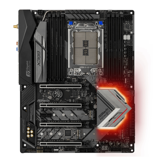
Page 15: Motherboard Layout
T: USB7 RJ-45 B: USB8 USB 3.1 CPU_OPT/ Top: T: USB31_TA_1 W_PUMP CHA_FAN1 RJ-45 B: USB31_TC_1 PCIE1 U2_1 BIOS PCIE2 X399 X399 Gaming PCIE3 FATAL AUDIO CODEC PCIE4 PCIE5 Reset Power PLED PWRBTN USB_3_4 USB_1_2 USB3_9_10 COM1 CHA_FAN2 SPK_PLED1 CLRC... - Page 16 No. Description Chassis Fan / Waterpump Fan Connector (CHA_FAN3/W_PUMP) 4 pin 12V Power Connector (ATX12V2) 2 x 288-pin DDR4 DIMM Slots (DDR4_D2, DDR4_C2) 2 x 288-pin DDR4 DIMM Slots (DDR4_D1, DDR4_C1) CPU Xtreme OC Switch (MOS_PROCHOT1) 2 x 288-pin DDR4 DIMM Slots (DDR4_A1, DDR4_B1) 2 x 288-pin DDR4 DIMM Slots (DDR4_A2, DDR4_B2) CPU Fan Connector (CPU_FAN1) 8 pin 12V Power Connector (ATX12V1)
-
Page 17: I/O Panel
Fatal1ty X399 Professional Gaming Series 1.4 I/O Panel No. Description No. Description PS/2 Mouse/Keyboard Port (PS2_KB1) USB 3.0 Ports (USB3_7_8) Central / Bass (Orange) USB 3.0 Ports (USB3_5_6)**** Rear Speaker (Black) Microphone (Pink) Line In (Light Blue) Optical SPDIF Out Port Front Speaker (Lime)*** USB 3.0 Ports (USB3_3_4) 10 GLAN RJ-45 Port (AQUANTIA®... - Page 18 ** There are two LEDs on each LAN port. Please refer to the table below for the LAN port LED indications. ACT/LINK LED SPEED LED LAN Port Activity / Link LED Speed LED Status Description Status Description No Link Orange 100Mbps/1Gbps/2.5Gbps Blinking Data Activity...
- Page 19 Fatal1ty X399 Professional Gaming Series 1.5 WiFi-802.11ac Module and ASRock WiFi 2.4/5 GHz Antenna WiFi-802.11ac + BT Module This motherboard comes with an exclusive WiFi 802.11 a/b/g/n/ac + BT v4.2 module (pre-installed on the rear I/O panel) that offers support for WiFi 802.11 a/b/ g/n/ac connectivity standards and Bluetooth v4.2.
- Page 20 WiFi Antennas Installation Guide Step 1 Prepare the WiFi 2.4/5 GHz Antennas that come with the package. Step 2 Connect the two WiFi 2.4/5 GHz Antennas to the antenna connectors. Turn the antenna clock- wise until it is securely connected. Step 3 Set the WiFi 2.4/5 GHz Antenna as shown in the illustration.
-
Page 21: Chapter 2 Installation
Fatal1ty X399 Professional Gaming Series Chapter 2 Installation This is an ATX form factor motherboard. Before you install the motherboard, study the configuration of your chassis to ensure that the motherboard fits into it. Pre-installation Precautions Take note of the following precautions before you install motherboard components or change any motherboard settings. -
Page 22: Installing The Cpu
2.1 Installing the CPU Tutorial Video Unplug all power cables before installing the CPU. - Page 23 Fatal1ty X399 Professional Gaming Series...
- Page 24 Carr ier Frame with CPU Rail Frame Please make sure that the carrier frame with CPU is closely attached to the rail frame while inserting it. Install the orange carrier frame with CPU. Don’t separate them.
- Page 25 Fatal1ty X399 Professional Gaming Series...
-
Page 26: Installing The Cpu Liquid Cooler
2.2 Installing the CPU Liquid Cooler After you install the CPU into this motherboard, it is necessary to install a larger heatsink and cooling fan to dissipate heat. You also need to spray thermal grease between the CPU and the heatsink to improve heat dissipation. Make sure that the CPU and the heatsink are securely fastened and in good contact with each other. - Page 27 Fatal1ty X399 Professional Gaming Series...
-
Page 28: Installation Of Memory Modules (Dimm)
2.3 Installation of Memory Modules (DIMM) This motherboard provides eight 288-pin DDR4 (Double Data Rate 4) DIMM slots, and supports Quad Channel Memory Technology. 1. For quad channel configuration, you always need to install identical (the same brand, speed, size and chip-type) DDR4 DIMM pairs. 2. - Page 29 Fatal1ty X399 Professional Gaming Series • If only two memory modules are installed in the DDR4 DIMM slots, then Dual Channel Memory Technology is activated. If three memory modules are installed, then Triple Channel Memory Technology is activated. If more than four memory modules are installed in the DDR4 DIMM slots, then Quad Channel Memory Technology is activated.
-
Page 30: Expansion Slots (Pci Express Slots)
2.4 Expansion Slots (PCI Express Slots) There are 5 PCI Express slots on the motherboard. Before installing an expansion card, please make sure that the power supply is switched off or the power cord is unplugged. Please read the documentation of the expansion card and make necessary hardware settings for the card before you start the installation. -
Page 31: Onboard Headers And Connectors
Fatal1ty X399 Professional Gaming Series 2.5 Onboard Headers and Connectors Onboard headers and connectors are NOT jumpers. Do NOT place jumper caps over these headers and connectors. Placing jumper caps over the headers and connectors will cause permanent damage to the motherboard. System Panel Header Connect the power PLED+... - Page 32 Power LED and Speaker Please connect the SPEAKER DUMMY Header chassis power LED and DUMMY (7-pin SPK_PLED1) the chassis speaker to this (see p.7, No. 26) header. PLED+ PLED+ PLED- Serial ATA3 Connectors These eight SATA3 (SATA3_1_2: connectors support SATA see p.7, No.
- Page 33 Fatal1ty X399 Professional Gaming Series (19-pin USB3_11_12) Vbus Vbus Vbus IntA_PB_SSRX- (see p.7, No. 11) IntA_PA_SSRX- IntA_PB_SSRX+ IntA_PA_SSRX+ IntA_PB_SSTX- IntA_PA_SSTX- IntA_PB_SSTX+ IntA_PA_SSTX+ IntA_PB_D- IntA_PA_D- IntA_PB_D+ IntA_PA_D+ Dummy Front Panel Audio This header is for PRESENCE# Headers connecting audio devices MIC_RET OUT_RET (9-pin HD_AUDIO1) to the front audio panel.
- Page 34 Chassis Optional/Water This motherboard FAN_VOLTAGE Pump Fan Connector provides a 4-Pin water FAN_SPEED FAN_SPEED_CONTROL (4-pin CHA_FAN3/W_ cooling chassis fan PUMP) connectors. If you plan to (see p.7, No. 1) connect a 3-Pin chassis water cooler fan, please connect it to Pin 1-3. CPU Fan Connector This motherboard FAN_SPEED_CONTROL...
- Page 35 Fatal1ty X399 Professional Gaming Series ATX 12V Power Please connect an ATX Connector 12V power supply to this (4-pin ATX12V2) connector. (see p.7, No. 2) *The power supply plug fits into this connector in only one orientation. Graphics 12V Power This motherboard pro- Connector vides a 6-pin Graphics...
- Page 36 U.2 Connector This connector supports U.2 (36-pin U2_1) NVM Express storage devices up (see p.7, No. 13) to Gen3 x4 (32 Gb/s). * If U.2 Connector is plugged, M2_1 will be disabled.
-
Page 37: Smart Switches
Fatal1ty X399 Professional Gaming Series 2.6 Smart Switches The motherboard has five smart switches: Power Switch, Reset Switch, Clear CMOS Switch, CPU Xtreme OC Switch and BIOS Flashback Switch. Power Switch Power Switch allows users (PWRBTN) to quickly turn on/off the Power (see p.7, No. - Page 38 (BIOS_FB1) to flash the BIOS. (see p.9, No. 19) ASRock BIOS Flashback feature allows you to update BIOS without powering on the system, even without CPU. To use the USB BIOS Flashback function, Please follow the steps below. 1. Download the latest BIOS file from ASRock's website : http://www.asrock.com.
-
Page 39: Dr. Debug
Fatal1ty X399 Professional Gaming Series 2.7 Dr. Debug Dr. Debug is used to provide code information, which makes troubleshooting even easier. Please see the diagrams below for reading the Dr. Debug codes. Code Description Please check if the CPU is installed correctly and then clear CMOS. - Page 40 Problem related to USB devices. Please try removing all USB devices. Problem related to memory. Please re-install the CPU and memory then clear CMOS. If the problem still exists, please install only one memory module or try using other memory modules.
-
Page 41: Sli Tm , 3-Way Sli Tm Tm Tm Operation
Fatal1ty X399 Professional Gaming Series 2.8 SLI , 3-Way SLI , 4-Way SLI and Quad SLI Operation Guide This motherboard supports NVIDIA® SLI , 3-way SLI , 4-way SLI and Quad (Scalable Link Interface) technology that allows you to install up to four identical PCI Express x16 graphics cards. - Page 42 Step 3 Align and insert the ASRock SLI_HB_ Bridge_3S Card (if you install NVIDIA® high-bandwidth graphics cards) to the goldfingers on each graphics card. Make sure the ASRock SLI_HB_Bridge_3S Card is firmly in place. SLI_HB_Bridge_3S Car d ASRock SLI_HB_Bridge_3S Card (For NVIDIA®...
-
Page 43: Installing Three Sli Tm -Ready Graphics Cards
PCI Express graphics card are connected. Repeat this step on the three graphics cards. Step 3 Align and insert the ASRock 3-Way SLI Bridge Card to the goldfingers on each graphics card. Make sure the ASRock 3-Way SLI Bridge Card is firmly in place. - Page 44 Step 4 Connect a VGA cable or a DVI cable to the monitor connector or the DVI connector of the graphics card that is inserted to PCIE1 slot. *If possible, please plug the PSU’s power cable to GFX_12V1.
-
Page 45: Installing Four Sli Tm -Ready Graphics Cards
Repeat this step on the three graphics cards. Step 3 Align and insert the ASRock 4-Way SLI-S111 Bridge Card to the goldfingers on each graphics card. Make sure the ASRock 4-Way SLI-S111 Bridge Card is firmly in place. ASRock 4-Way SLI-S111 Bridge Card... - Page 46 Step 4 Connect a VGA cable or a DVI cable to the monitor connector or the DVI connector of the graphics card that is inserted to PCIE1 slot. *If possible, please plug the PSU’s power cable to GFX_12V1.
-
Page 47: Driver Installation And Setup
Fatal1ty X399 Professional Gaming Series 2.8.4 Driver Installation and Setup Install the graphics card drivers to your system. After that, you can enable the Multi-Graphics Processing Unit (GPU) in the NVIDIA® nView system tray utility. Please follow the below procedures to enable the multi-GPU. Step 1 Double-click the NVIDIA Control Panel icon in the Windows®... -
Page 48: Tm , 4-Way Crossfirex
2.9 CrossFireX , 3-Way CrossFireX , 4-Way CrossFireX Quad CrossFireX Operation Guide This motherboard supports CrossFireX , 3-way CrossFireX , 4-way CrossFireX and Quad CrossFireX that allows you to install up to four identical PCI Express x16 graphics cards. 1. You should only use identical CrossFireX -ready graphics cards that are AMD certified. -
Page 49: Installing Three Crossfirex
Fatal1ty X399 Professional Gaming Series Step 3 Connect a VGA cable or a DVI cable to the monitor connector or the DVI connec- tor of the graphics card that is inserted to PCIE1 slot. 2.9.2 Installing Three CrossFireX -Ready Graphics Cards Step 1 Insert one graphics card into PCIE1 slot, another graphics card to PCIE2 slot, and... -
Page 50: Tm -Ready Graphics Cards
2.9.3 Installing Four CrossFireX -Ready Graphics Cards Step 1 Insert one graphics card into PCIE1 slot, another graphics card into PCIE2 slot, the third graphics card into PCIE4 slot and the last graphics card into PCIE5 slot. Make sure that the cards are properly seated on the slots. -
Page 51: Driver Installation And Setup
Fatal1ty X399 Professional Gaming Series 2.9.4 Driver Installation and Setup Step 1 Power on your computer and boot into OS. Step 2 Remove the AMD drivers if you have any VGA drivers installed in your system. The Catalyst Uninstaller is an optional download. We recommend using this utility to uninstall any previously installed Catalyst drivers prior to installation. -
Page 52: M2_2)
2.10 M.2_SSD (NGFF) Module Installation Guide (M2_1 and M2_2) The M.2, also known as the Next Generation Form Factor (NGFF), is a small size and versatile card edge connector that aims to replace mPCIe and mSATA. The Ultra M.2 Socket (M2_1 and M2_2) support SATA3 6.0 Gb/s module and M.2 PCI Express module up to Gen3 x4 (32 Gb/s). - Page 53 Fatal1ty X399 Professional Gaming Series Step 3 Move the standoff based on the module type and length. The standoff is placed at the nut location D by default. Skip Step 3 and 4 and go straight to Step 5 if you are going to use the default nut.
- Page 54 Step 6 Tighten the screw with a screwdriver to secure the module into place. Please do not overtighten the screw NUT2 NUT1 as this might damage the module.
- Page 55 Fatal1ty X399 Professional Gaming Series M.2_SSD (NGFF) Module Support List Vendor Interface Length ADATA SATA3 2280 AXNS381E-128GM-B ADATA SATA3 2280 ASU800NS38-256GT-C ADATA SATA3 2280 AXNS381E-256GM-B ADATA SATA3 2280 ASU800NS38-512GT-C ADATA PCIe3 x4 2280 ASX7000NP-128GT-C ADATA PCIe3 x4 2280 ASX8000NP-256GM-C ADATA PCIe3 x4 2280 ASX7000NP-256GT-C...
- Page 56 Transcend SATA3 2242 TS256GMTS400 Transcend SATA3 2260 TS512GMTS600 Transcend SATA3 2280 TS512GMTS800 V-Color SATA3 2280 VLM100-120G-2280B-RD V-Color SATA3 2280 VLM100-240G-2280B-RD V-Color SATA3 2280 VLM100-240G-2280RGB V-Color SATA3 2280 VSM100-240G-2280 SATA3 2280 WDS100T1B0B-00AS40 SATA3 2280 WDS240G1G0B-00RC30 PCIe3 x4 2280 WDS256G1X0C-00ENX0 (NVME) PCIe3 x4 2280 WDS512G1X0C-00ENX0 (NVME)
- Page 57 Fatal1ty X399 Professional Gaming Series 2.11 M.2_SSD (NGFF) Module Installation Guide (M2_3) The M.2, also known as the Next Generation Form Factor (NGFF), is a small size and versatile card edge connector that aims to replace mPCIe and mSATA. The Ultra M.2 Socket (M2_3) support SATA3 6.0 Gb/s module and M.2 PCI Express module up to Gen3 x4 (32 Gb/s).
- Page 58 Step 3 Move the standoff based on the module type and length. The standoff is placed at the nut location D by default. Skip Step 3 and 4 and go straight to Step 5 if you are going to use the default nut. Otherwise, release the standoff by hand.
- Page 59 Fatal1ty X399 Professional Gaming Series M.2_SSD (NGFF) Module Support List Vendor Interface Length ADATA SATA3 2230 AXNS330E-32GM-B ADATA SATA3 2280 AXNS381E-128GM-B ADATA SATA3 2280 ASU800NS38-256GT-C ADATA SATA3 2280 AXNS381E-256GM-B ADATA SATA3 2280 ASU800NS38-512GT-C ADATA PCIe3 x4 2280 ASX7000NP-128GT-C ADATA PCIe3 x4 2280 ASX8000NP-256GM-C ADATA...
- Page 60 Transcend SATA3 2242 TS256GMTS400 Transcend SATA3 2260 TS512GMTS600 Transcend SATA3 2280 TS512GMTS800 V-Color SATA3 2280 VLM100-120G-2280B-RD V-Color SATA3 2280 VLM100-240G-2280B-RD V-Color SATA3 2280 VLM100-240G-2280RGB V-Color SATA3 2280 VSM100-240G-2280 SATA3 2280 WDS100T1B0B-00AS40 SATA3 2280 WDS240G1G0B-00RC30 PCIe3 x4 2280 WDS256G1X0C-00ENX0 (NVME) PCIe3 x4 2280 WDS512G1X0C-00ENX0 (NVME)
-
Page 61: Chapter 3 Software And Utilities Operation
Fatal1ty X399 Professional Gaming Series Chapter 3 Software and Utilities Operation 3.1 Installing Drivers The Support CD that comes with the motherboard contains necessary drivers and useful utilities that enhance the motherboard’s features. Running The Support CD To begin using the support CD, insert the CD into your CD-ROM drive. The CD automatically displays the Main Menu if “AUTORUN”... -
Page 62: F-Stream
3.2 F-Stream F-Stream is ASRock’s multi purpose software suite with a new interface, more new features and improved utilities. 3.2.1 Installing F-Stream F-Stream can be downloaded from ASRock Live Update & APP Shop. After the installation, you will find the icon “F-Stream“ on your desktop. Double-click the “F-Stream“... - Page 63 Fatal1ty X399 Professional Gaming Series OC Tweaker Configurations for overclocking the system. System Info View information about the system. *The System Browser tab may not appear for certain models.
- Page 64 Configure up to five different fan speeds using the graph. The fans will automatically shift to the next speed level when the assigned temperature is met. Settings Configure ASRock F-Stream. Click to select "Auto run at Windows Startup" if you want F-Stream to be launched when you start up the Windows operating system.
-
Page 65: Asrock Live Update & App Shop
Double-click on your desktop to access ASRock Live Update & APP Shop utility. *You need to be connected to the Internet to download apps from the ASRock Live Update & APP Shop. 3.3.1 UI Overview Category Panel Hot News... -
Page 66: Apps
3.3.2 Apps When the "Apps" tab is selected, you will see all the available apps on screen for you to download. Installing an App Step 1 Find the app you want to install. The most recommended app appears on the left side of the screen. The other various apps are shown on the right. - Page 67 Fatal1ty X399 Professional Gaming Series Step 3 If you want to install the app, click on the red icon to start downloading. Step 4 When installation completes, you can find the green "Installed" icon appears on the upper right corner. To uninstall it, simply click on the trash can icon *The trash icon may not appear for certain apps.
- Page 68 Upgrading an App You can only upgrade the apps you have already installed. When there is an available new version for your app, you will find the mark of "New Version" appears below the installed app icon. Step 1 Click on the app icon to see more details. Step 2 Click on the yellow icon to start upgrading.
-
Page 69: Bios & Drivers
Fatal1ty X399 Professional Gaming Series 3.3.3 BIOS & Drivers Installing BIOS or Drivers When the "BIOS & Drivers" tab is selected, you will see a list of recommended or critical updates for the BIOS or drivers. Please update them all soon. Step 1 Please check the item information before update. -
Page 70: Setting
3.3.4 Setting In the "Setting" page, you can change the language, select the server location, and determine if you want to automatically run the ASRock Live Update & APP Shop on Windows startup. -
Page 71: Creative Soundblaster Cinema3
Fatal1ty X399 Professional Gaming Series 3.4 Creative SoundBlaster Cinema3 The SoundBlaster Cinema3, powered by the SBX Pro Studio technologies, is designed to bring the same great audio experience found in live performances, films, and recording studios to the PC. With this utility, you can easily enhance your audio environment in five modes, including Headphones, Speakers, Music, Movie, Game, Voice and Custom. -
Page 72: Asrock Rgb Led
3.5 ASRock RGB LED ASRock RGB LED is a lighting control utility specifically designed for unique individuals with sophisticated tastes to build their own stylish colorful lighting system. Simply by connecting the LED strip, you can customize various lighting schemes and patterns, including Static, Breathing, Strobe, Cycling, Music, Wave and more. - Page 73 ASRock RGB LED Utility Now you can adjust the RGB LED color through the ASRock RGB LED utility. Download this utility from the ASRock Live Update & APP Shop and start coloring your PC style your way! Drag the tab to customize your preference.
-
Page 74: Chapter 4 Uefi Setup Utility
Chapter 4 UEFI SETUP UTILITY 4.1 Introduction This section explains how to use the UEFI SETUP UTILITY to configure your system. You may run the UEFI SETUP UTILITY by pressing <F2> or <Del> right after you power on the computer, otherwise, the Power-On-Self-Test (POST) will continue with its test routines. -
Page 75: Navigation Keys
Fatal1ty X399 Professional Gaming Series 4.1.2 Navigation Keys Use < > key or < > key to choose among the selections on the menu bar, and use < > key or < > key to move the cursor up or down to select items, then press <Enter>... -
Page 76: Main Screen
4.2 Main Screen When you enter the UEFI SETUP UTILITY, the Main screen will appear and display the system overview. -
Page 77: Oc Tweaker Screen
Fatal1ty X399 Professional Gaming Series 4.3 OC Tweaker Screen In the OC Tweaker screen, you can set up overclocking features. Because the UEFI software is constantly being updated, the following UEFI setup screens and descriptions are for reference purpose only, and they may not exactly match what you see on your screen. -
Page 78: Dram Timing Configuration
DRAM Timing Configuration Load XMP Setting Load XMP settings to overclock the DDR memory and perform beyond standard specifications. Voltage Configuration Voltage Mode [OC] If this option is selected, there is larger range voltage for overclocking. [Stable] If this option is selected, there is smaller range voltage for stable system. CPU Vcore Voltage Configure the voltage for the CPU Vcore. - Page 79 Fatal1ty X399 Professional Gaming Series DRAM_CD Voltage Use this to select DRAM_CD Voltage. The default value is [Auto]. VTT_DDR Configure the VTT DDR voltage. The default value is [Auto]. VTT_DDR_CD Configure the VTT DDR_CD voltage. The default value is [Auto]. VPPM Configure the voltage for the VPPM.
-
Page 80: Advanced Screen
4.4 Advanced Screen In this section, you may set the configurations for the following items: CPU Configuration, North Bridge Configuration, South Bridge Configuration, Storage- Configuration, Super IO Configuration, ACPI Configuration, AMD PBS and AMD CBS. Setting wrong values in this section may cause the system to malfunction. UEFI Configuration Active Page on Entry Select the default page when entering the UEFI setup utility. -
Page 81: Cpu Configuration
Fatal1ty X399 Professional Gaming Series 4.4.1 CPU Configuration AMD fTPM Switch Use this to enable or disable AMD CPU fTPM. SVM Mode When this option is set to [Enabled], a VMM (Virtual Machine Architecture) can utilize the additional hardware capabilities provided by AMD-V. The default value is [Enabled]. -
Page 82: North Bridge Configuration
4.4.2 North Bridge Configuration IOMMU Use this to configure IOMMU. The default value of this feature is [Auto]. SR-IOV Support Enable/disable the SR-IOV (Single Root IO Virtualization Support) if the system has SR-IOV capable PCIe devices. -
Page 83: South Bridge Configuration
Fatal1ty X399 Professional Gaming Series 4.4.3 South Bridge Configuration Deep Sleep Configure deep sleep mode for power saving when the computer is shut down. Restore on AC/Power Loss Select the power state after a power failure. If [Power Off] is selected, the power will remain off when the power recovers. -
Page 84: Storage Configuration
4.4.4 Storage Configuration SATA Controller(s) Enable/disable the SATA controllers. SATA Mode AHCI: Supports new features that improve performance. RAID: Combine multiple disk drives into a logical unit. SATA Hot Plug Enable/disable the SATA Hot Plug function. -
Page 85: Super Io Configuration
Fatal1ty X399 Professional Gaming Series 4.4.5 Super IO Configuration Serial Port Enable or disable the Serial port. Serial Port Address Select the address of the Serial port. PS2 Y-Cable Enable the PS2 Y-Cable or set this option to Auto. -
Page 86: Acpi Configuration
4.4.6 ACPI Configuration Suspend to RAM It is recommended to select auto for ACPI S3 power saving. ACPI HPET Table Enable the High Precision Event Timer for better performance and to pass WHQL tests. PS/2 Keyboard Power On Allow the system to be waked up by a PS/2 Keyboard. PCIE Devices Power On Allow the system to be waked up by a PCIE device and enable wake on LAN. -
Page 87: Amd Pbs
Fatal1ty X399 Professional Gaming Series 4.4.7 AMD PBS PCIe x16 Switch Configure the PCIe x16 Switch. Promontory PCIe Switch Configure the Promontory PCIe Switch. -
Page 88: Amd Cbs
4.4.8 AMD CBS DRAM Timing Configuration Overclock Configure the memory overclock settings. Custom Pstates / Throttling Custom Pstates0 Custom P-State0 or leave this item to [Auto]. Custom Pstates1 Custom P-State1 or leave this item to [Auto]. Custom Pstates2 Custom P-State2 or leave this item to [Auto]. Custom Pstates3 Custom P-State3 or leave this item to [Auto]. - Page 89 Fatal1ty X399 Professional Gaming Series Custom Pstates5 Custom P-State5 or leave this item to [Auto]. Custom Pstates6 Custom P-State6 or leave this item to [Auto]. Custom Pstates7 Custom P-State7 or leave this item to [Auto]. Relaxed EDC throttling [Disabled] If this option is selected, part-specific EDC throttling protection is enabled. [Enabled] Select this option to reduce the amount of time the processor will throttle.
- Page 90 Opcache Control Enables or disables the Opcache. OC Mode OC1 - 16 cores/3.6GHz on 1.3375V OC2 - 8 cores/3.7GHz on 1.369V OC3 - 4 cores/3.75GHz on 1.374V\nMax Stress - 16 cores/3.8GHz on 1.400V SEV-ES ASID Space Limit SEV VMs using ASIDs below the SEV-ES ASID Space Limit must enable the SEV-ES feature. The valid values for this field are from 0x1 (1) - 0x10 (16).
-
Page 91: Memory Interleaving
Fatal1ty X399 Professional Gaming Series GMI encryption control GMI encryption control Control GMI link encryption xGMI encryption control Control xGMI link encryption CC6 memory region encryption Control whether or not the CC6 save/restore memory is encrypted Location of private memory regions Controls whether or not the private memory regions (PSP, SMU and CC6) are at the top of DRAM or distributed. - Page 92 UMC Common Options DDR4 Common Options DRAM Controller Configuration DRAM Controller Configuration DRAM Power Options Cmd2T Select between 1T and 2T mode on ADDR/CMD Gear Down Mode Configure the Gear Down Mode. CAD Bus Configuration CAD Bus Timing User Controls Setup time on CAD bus signals to Auto or Manual CAD Bus Drive Strength User Controls Drive Strength on CAD bus signals to Auto or Manual...
- Page 93 Fatal1ty X399 Professional Gaming Series Data Scramble Data scrambling: DataScrambleEn DRAM Memory Mapping Chipselect Interleaving Interleave memory blocks across the DRAM chip selects for node 0. BankGroupSwap Configure the BankGroupSwap. BankGroupSwapAlt Configure BankGroupSwapAlt. Address Hash Bank Configure the bank address hashing. Address Hash CS Configure the CS address hashing.
- Page 94 IOMMU Use this to enable or disable IOMMU. The default value of this feature is [Disabled]. Determinism Slider [Auto] Use default performance determinism settings cTDP Control [Auto] Use the fused cTDP. [Manual] User can set customized cTDP. Fan Control [Auto] Use the default fan controller settings.
- Page 95 Fatal1ty X399 Professional Gaming Series FCH Common Options SATA Configuration Options SATA Controller Disable or enable OnChip SATA controller Sata RAS Support Disable or enable Sata RAS Support Sata Disabled AHCI Prefetch Function Configure the Sata Disabled AHCI Prefetch function. Aggresive SATA Device Sleep Port 0 Configure the Aggresive SATA Device Sleep Port 0.
- Page 96 DRAM Memory Mapping Chipselect Interleaving Interleave memory blocks across the DRAM chip selects for node 0. BankGroupSwap Configure the BankGroupSwap. BankGroupSwapAlt Configure the BankGroupSwapAlt. Address Hash Bank Configure the bank address hashing. Address Hash CS Configure the CS address hashing. NVDIMM Memory MBIST MBIST Enable...
-
Page 97: Tools
Fatal1ty X399 Professional Gaming Series 4.5 Tools RGB LED ASRock RGB LED allows you to adjust the RGB LED color to your liking. Easy RAID Installer Easy RAID Installer helps you to copy the RAID driver from the support CD to your USB storage device. -
Page 98: Network Configuration
Save UEFI files in your USB storage device and run Instant Flash to update your UEFI. Internet Flash - DHCP (Auto IP), Auto ASRock Internet Flash downloads and updates the latest UEFI firmware version from our servers for you. Please setup network configuration before using Internet Flash. -
Page 99: Hardware Health Event Monitoring Screen
Fatal1ty X399 Professional Gaming Series 4.6 Hardware Health Event Monitoring Screen This section allows you to monitor the status of the hardware on your system, including the parameters of the CPU temperature, motherboard temperature, fan speed and voltage. Fan-Tastic Tuning Select a fan mode for CPU Fans 1&2, or choose Customize to set 5 CPU temperatures and assign a respective fan speed for each temperature. - Page 100 CPU Optional Fan Temp Source Select a fan temperature source for CPU Optional fan. Chassis Fan 1 Setting Select a fan mode for Chassis Fan 1, or choose Customize to set 5 CPU temperatures and assign a respective fan speed for each temperature. Chassis Fan 1 Temp Source Select a fan temperature source for Chassis Fan 1.
-
Page 101: Security Screen
Fatal1ty X399 Professional Gaming Series 4.7 Security Screen In this section you may set or change the supervisor/user password for the system. You may also clear the user password. Supervisor Password Set or change the password for the administrator account. Only the administrator has authority to change the settings in the UEFI Setup Utility. -
Page 102: Boot Screen
4.8 Boot Screen This section displays the available devices on your system for you to configure the boot settings and the boot priority. Fast Boot Fast Boot minimizes your computer's boot time. In fast mode you may not boot from an USB storage device. Boot From Onboard LAN Allow the system to be waked up by the onboard LAN. - Page 103 Fatal1ty X399 Professional Gaming Series AddOn ROM Display Enable AddOn ROM Display to see the AddOn ROM messages or configure the AddOn ROM if you've enabled Full Screen Logo. Disable for faster boot speed. CSM (Compatibility Support Module) Enable to launch the Compatibility Support Module. Please do not disable unless you’re running a WHCK test.
-
Page 104: Exit Screen
4.9 Exit Screen Save Changes and Exit When you select this option the following message, “Save configuration changes and exit setup?” will pop out. Select [OK] to save changes and exit the UEFI SETUP UTILITY. Discard Changes and Exit When you select this option the following message, “Discard changes and exit setup?”... -
Page 105: Contact Information
Fatal1ty X399 Professional Gaming Series Contact Information If you need to contact ASRock or want to know more about ASRock, you’re welcome to visit ASRock’s website at http://www.asrock.com; or you may contact your dealer for further information. For technical questions, please submit a support request form at http://www.asrock.com/support/tsd.asp...
Need help?
Do you have a question about the X399 Gaming and is the answer not in the manual?
Questions and answers