Table of Contents
Advertisement
Advertisement
Table of Contents

Related Manuals for ASROCK X399M Taichi


Summary of Contents for ASROCK X399M Taichi
- Page 2 (including damages for loss of profits, loss of business, loss of data, interruption of business and the like), even if ASRock has been advised of the possibility of such damages arising from any defect or error in the documentation or product.
- Page 3 If you require assistance please call ASRock Tel : +886-2-28965588 ext.123 (Standard International call charges apply)
- Page 4 CE Warning This device complies with directive 2014/53/EU issued by the Commision of the European Community. This equipment complies with EU radiation exposure limits set forth for an uncontrolled environment. This equipment should be installed and operated with minimum distance 20cm between the radiator &...
-
Page 6: Table Of Contents
Contents Chapter 1 Introduction Package Contents Specifications Motherboard Layout I/O Panel Chapter 2 Installation Installing the CPU Installing the CPU Liquid Cooler Installation of Memory Modules (DIMM) Expansion Slots (PCI Express Slots) Onboard Headers and Connectors Smart Switches Dr. Debug and Quad SLI Operation Guide 2.8.1 Installing Two SLI... - Page 7 Chapter 3 Software and Utilities Operation Installing Drivers A-Tuning 3.2.1 Installing A-Tuning 3.2.2 Using A-Tuning ASRock Live Update & APP Shop 3.3.1 UI Overview 3.3.2 Apps 3.3.3 BIOS & Drivers 3.3.4 Setting ASRock RGB LED Chapter 4 UEFI SETUP UTILITY...
- Page 8 4.6.5 Super IO Configuration 4.6.6 ACPI Configuration 4.6.7 Trusted Computing 4.6.8 AMD PBS 4.6.9 AMD CBS Tools Hardware Health Event Monitoring Screen Security Screen 4.10 Boot Screen 4.11 Exit Screen...
-
Page 9: Chapter 1 Introduction
If you require technical support related to this mother- board, please visit our website for specific information about the model you are using. You may find the latest VGA cards and CPU support list on ASRock’s website as well. ASRock website http://www.asrock.com. -
Page 10: Specifications
• 4 x DDR4 DIMM Slots • Supports DDR4 3600+(OC)/3200(OC)/2933(OC)/ 2667/2400/2133 ECC & non-ECC, un-buffered memory (U-DIMM)* * Please refer to Memory Support List on ASRock’s website for more information. (http://www.asrock.com/) • Max. capacity of system memory: 64GB • 15μ Gold Contact in DIMM Slots Expansion • 3 x PCI Express 3.0 x16 Slots (PCIE1/PCIE2/PCIE3: single at... - Page 11 X399M Taichi • Supports Purity Sound - Nichicon Fine Gold Series Audio Caps - 120dB SNR DAC with Differential Amplifier - NE5532 Premium Headset Amplifier for Front Panel Audio Connector (Supports up to 600 Ohm headsets) - Pure Power-In - Direct Drive Technology...
- Page 12 PCI Express module up to Gen3 x4 (32 Gb/s)* * Supports NVMe RAID (RAID 0, RAID 1 and RAID 10) * Supports NVMe SSD as boot disks * Supports ASRock U.2 Kit • 1 x U.2 Connector * If U.2 Connector is plugged, M2_1 will be disabled Connector • 1 x TPM Header...
- Page 13 X399M Taichi * CPU_FAN1, CHA_FAN1, CHA_FAN2, CPU_OPT/W_PUMP and CHA_FAN3/W_PUMP can auto detect if 3-pin or 4-pin fan is in use. • 1 x 24 pin ATX Power Connector (Hi-Density Power Connector) • 1 x 8 pin 12V Power Connector (Hi-Density Power Connector) • 1 x 4 pin 12V Power Connector (Hi-Density Power...
- Page 14 • ErP/EuP ready (ErP/EuP ready power supply is required) * For detailed product information, please visit our website: http://www.asrock.com Please realize that there is a certain risk involved with overclocking, including adjusting the setting in the BIOS, applying Untied Overclocking Technology, or using third-party overclocking tools.
-
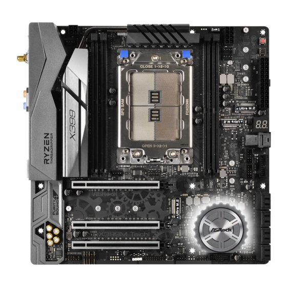
Page 15: Motherboard Layout
X399M Taichi 1.3 Motherboard Layout MOS_PROCHOT1 BIOS _FB1 PWRBTN1 ATX12V2 CHA_FAN3/ RSTBTN1 W_PUMP CPU_FAN1 CPU_OPT/ W_PUMP M2_WIFI_1 USB 3.1 Gen1 T: USB3 B: USB4 TR4 Socket (4094 pins) M2_3 M2_2 Debug USB 3.1 Gen1 T: USB5 B: USB6 U2_1 USB_3_4 USB 3.1 Gen1... - Page 16 No. Description Chassis Fan / Waterpump Fan Connector (CHA_FAN3/W_PUMP) 4 pin 12V Power Connector (ATX12V2) 2 x 288-pin DDR4 DIMM Slots (DDR4_D1, DDR4_C1) 2 x 288-pin DDR4 DIMM Slots (DDR4_A1, DDR4_B1) CPU Xtreme OC Switch (MOS_PROCHOT1) 8 pin 12V Power Connector (ATX12V1) CPU Fan Connector (CPU_FAN1) CPU Fan / Waterpump Fan Connector (CPU_OPT/W_PUMP) Power Button (PWRBTN1)
-
Page 17: I/O Panel
X399M Taichi 1.4 I/O Panel No. Description No. Description PS/2 Mouse/Keyboard Port (PS2_KB1) USB 3.1 Gen1 Ports (USB3_7_8) Central / Bass (Orange) USB 3.1 Gen1 Ports (USB3_5_6)*** Rear Speaker (Black) Microphone (Pink) Line In (Light Blue) Optical SPDIF Out Port Front Speaker (Lime)** USB 3.1 Gen1 Ports (USB3_3_4) - Page 18 ** If you use a 2-channel speaker, please connect the speaker’s plug into “Front Speaker Jack”. See the table below for connection details in accordance with the type of speaker you use. Audio Output Front Speaker Rear Speaker Central / Bass Line In Channels (No.
- Page 19 X399M Taichi 1.5 WiFi-802.11ac Module and ASRock WiFi 2.4/5 GHz Antenna WiFi-802.11ac + BT Module This motherboard comes with an exclusive WiFi 802.11 a/b/g/n/ac + BT v4.2 module (pre-installed on the rear I/O panel) that offers support for WiFi 802.11 a/b/ g/n/ac connectivity standards and Bluetooth v4.2.
- Page 20 WiFi Antennas Installation Guide Step 1 Prepare the WiFi 2.4/5 GHz Antennas that come with the package. Step 2 Connect the two WiFi 2.4/5 GHz Antennas to the antenna connectors. Turn the antenna clock- wise until it is securely connected. Step 3 Set the WiFi 2.4/5 GHz Antenna as shown in the illustration.
-
Page 21: Chapter 2 Installation
X399M Taichi Chapter 2 Installation This is a Micro ATX form factor motherboard. Before you install the motherboard, study the configuration of your chassis to ensure that the motherboard fits into it. Pre-installation Precautions Take note of the following precautions before you install motherboard components or change any motherboard settings. -
Page 22: Installing The Cpu
2.1 Installing the CPU Tutorial Video Unplug all power cables before installing the CPU. - Page 23 X399M Taichi...
- Page 24 Carr ier Frame with CPU Rail Frame Please make sure that the carrier frame with CPU is closely attached to the rail frame while inserting it. Install the orange carrier frame with CPU. Don’t separate them.
- Page 25 X399M Taichi...
-
Page 26: Installing The Cpu Liquid Cooler
2.2 Installing the CPU Liquid Cooler After you install the CPU into this motherboard, it is necessary to install a larger heatsink and cooling fan to dissipate heat. You also need to spray thermal grease between the CPU and the heatsink to improve heat dissipation. Make sure that the CPU and the heatsink are securely fastened and in good contact with each other. - Page 27 X399M Taichi...
-
Page 28: Installation Of Memory Modules (Dimm)
2.3 Installation of Memory Modules (DIMM) This motherboard provides four 288-pin DDR4 (Double Data Rate 4) DIMM slots, and supports Quad Channel Memory Technology. 1. For dual channel configuration, you always need to install identical (the same brand, speed, size and chip-type) DDR4 DIMM pairs. 2. - Page 29 X399M Taichi...
-
Page 30: Expansion Slots (Pci Express Slots)
2.4 Expansion Slots (PCI Express Slots) There are 3 PCI Express slots on the motherboard. Before installing an expansion card, please make sure that the power supply is switched off or the power cord is unplugged. Please read the documentation of the expansion card and make necessary hardware settings for the card before you start the installation. -
Page 31: Onboard Headers And Connectors
X399M Taichi 2.5 Onboard Headers and Connectors Onboard headers and connectors are NOT jumpers. Do NOT place jumper caps over these headers and connectors. Placing jumper caps over the headers and connectors will cause permanent damage to the motherboard. System Panel Header... - Page 32 Power LED and Speaker Please connect the SPEAKER DUMMY Header chassis power LED and DUMMY (7-pin SPK_PLED1) the chassis speaker to this (see p.7, No. 22) header. PLED+ PLED+ PLED- Serial ATA3 Connectors These eight SATA3 (SATA3_1_2: connectors support SATA see p.7, No.
- Page 33 X399M Taichi (19-pin USB3_11_12) Vbus Vbus Vbus IntA_PB_SSRX- (see p.7, No. 14) IntA_PA_SSRX- IntA_PB_SSRX+ IntA_PA_SSRX+ IntA_PB_SSTX- IntA_PA_SSTX- IntA_PB_SSTX+ IntA_PA_SSTX+ IntA_PB_D- IntA_PA_D- IntA_PB_D+ IntA_PA_D+ Dummy Front Panel Audio This header is for PRESENCE# Headers connecting audio devices MIC_RET OUT_RET (9-pin HD_AUDIO1) to the front audio panel.
- Page 34 Chassis Optional/Water This motherboard FAN_VOLTAGE Pump Fan Connector provides a 4-Pin water FAN_SPEED FAN_SPEED_CONTROL (4-pin CHA_FAN3/W_ cooling chassis fan PUMP) connectors. If you plan to (see p.7, No. 1) connect a 3-Pin chassis water cooler fan, please connect it to Pin 1-3. CPU Fan Connector This motherboard FAN_SPEED_CONTROL...
- Page 35 X399M Taichi ATX 12V Power Please connect an ATX Connector 12V power supply to this (4-pin ATX12V2) connector. (see p.7, No. 2) *The power supply plug fits into this connector in only one orientation. TPM Header This connector supports Trusted...
-
Page 36: Smart Switches
2.6 Smart Switches The motherboard has five smart switches: Power Button, Reset Button, Clear CMOS Button, CPU Xtreme OC Switch and BIOS Flashback Button. Power Button Power Button allows users (PWRBTN1) to quickly turn on/off the (see p.7, No. 9) system. - Page 37 To use USB BIOS Flashback function, press the BIOS Flashback Button for three seconds. Please follow the steps below. 1. Download the latest BIOS file from ASRock's website : http://www.asrock.com. 2. Copy the BIOS file to your USB flash drive.Please make sure the file system of your USB flash drive must be FAT32.
-
Page 38: Dr. Debug
2.7 Dr. Debug Dr. Debug is used to provide code information, which makes troubleshooting even easier. Please see the diagrams below for reading the Dr. Debug codes. Code Description Please check if the CPU is installed correctly and then clear CMOS. - Page 39 X399M Taichi Problem related to USB devices. Please try removing all USB devices. Problem related to memory. Please re-install the CPU and memory then clear CMOS. If the problem still exists, please install only one memory module or try using other memory modules.
-
Page 40: Operation Guide
2.8 SLI and Quad SLI Operation Guide This motherboard supports NVIDIA® SLI and Quad SLI (Scalable Link Interface) technology that allows you to install up to two identical PCI Express x16 graphics cards. Requirements 1. You should only use identical SLI -ready graphics cards that are NVIDIA®... - Page 41 When the graphics cards are installed on PCIE1 and PCIE2: Align and insert the ASRock SLI_HB_ Bridge_1S Card to the goldfingers on each graphics card. Make sure the ASRock SLI_ HB_Bridge_1S Card is firmly in place. SLI_HB_Bridge_1S Car d ASRock SLI_HB_Bridge_1S Card...
-
Page 42: Driver Installation And Setup
2.8.2 Driver Installation and Setup Install the graphics card drivers to your system. After that, you can enable the Multi-Graphics Processing Unit (GPU) in the NVIDIA® nView system tray utility. Please follow the below procedures to enable the multi-GPU. Step 1 Double-click the NVIDIA Control Panel icon in the Windows®... -
Page 43: Tm Tm Operation Guide
X399M Taichi 2.9 CrossFireX and Quad CrossFireX Operation Guide This motherboard supports CrossFireX and Quad CrossFireX that allows you to install up to two identical PCI Express x16 graphics cards. 1. You should only use identical CrossFireX -ready graphics cards that are AMD certified. - Page 44 Step 3 Connect a VGA cable or a DVI cable to the monitor connector or the DVI connec- tor of the graphics card that is inserted to PCIE1 slot.
-
Page 45: Driver Installation And Setup
X399M Taichi 2.9.2 Driver Installation and Setup Step 1 Power on your computer and boot into OS. Step 2 Remove the AMD drivers if you have any VGA drivers installed in your system. The Catalyst Uninstaller is an optional download. We recommend using this utility to uninstall any previously installed Catalyst drivers prior to installation. -
Page 46: M.2_Ssd (Ngff) Module Installation Guide (M2_1)
2.10 M.2_SSD (NGFF) Module Installation Guide (M2_1) The M.2, also known as the Next Generation Form Factor (NGFF), is a small size and versatile card edge connector that aims to replace mPCIe and mSATA. The Ultra M.2 Socket (M2_1) supports M.2 PCI Express module up to Gen3 x4 (32 Gb/s). * If U.2 Connector is plugged, M2_1 will be disabled Installing the M.2_SSD (NGFF) Module Step 1... - Page 47 X399M Taichi Step 3 Move the standoff based on the module type and length. The standoff is placed at the nut location D by default. Skip Step 3 and 4 and go straight to Step 5 if you are going to use the default nut.
- Page 48 PCIe 2260 SD6PP4M-256G TEAM PCIe3 x4 2280 TM8FP2240G0C101 TEAM PCIe3 x4 2280 TM8FP2480GC110 PCIe3 x4 2280 WDS256G1X0C-00ENX0 (NVME) PCIe3 x4 2280 WDS512G1X0C-00ENX0 (NVME) For the latest updates of M.2_SSD (NFGG) module support list, please visit our website for details: http://www.asrock.com...
- Page 49 X399M Taichi 2.11 M.2_SSD (NGFF) Module Installation Guide (M2_2) The M.2, also known as the Next Generation Form Factor (NGFF), is a small size and versatile card edge connector that aims to replace mPCIe and mSATA. The Ultra M.2 Socket (M2_2) supports M.2 PCI Express module up to Gen3 x4 (32 Gb/s).
- Page 50 Step 3 Move the standoff based on the module type and length. The standoff is placed at the nut location D by default. Skip Step 3 and 4 and go straight to Step 5 if you are going to use the default nut. Otherwise, release the standoff by hand.
- Page 51 X399M Taichi M.2_SSD (NGFF) Module Support List Vendor Interface Length ADATA PCIe3 x4 2280 ASX7000NP-128GT-C ADATA PCIe3 x4 2280 ASX8000NP-256GM-C ADATA PCIe3 x4 2280 ASX7000NP-256GT-C ADATA PCIe3 x4 2280 ASX7000NP-512GT-C ADATA PCIe3 x4 2280 ASX8000NP-512GM-C Corsair PCIe3 x4 2280 CSSD-F240GBMP500...
-
Page 52: M.2_Ssd (Ngff) Module Installation Guide (M2_3)
2.12 M.2_SSD (NGFF) Module Installation Guide (M2_3) The M.2, also known as the Next Generation Form Factor (NGFF), is a small size and versatile card edge connector that aims to replace mPCIe and mSATA. The Ultra M.2 Socket (M2_3) supports SATA3 6.0 Gb/s module and M.2 PCI Express module up to Gen3 x4 (32 Gb/s). - Page 53 X399M Taichi Step 3 Move the standoff based on the module type and length. The standoff is placed at the nut location D by default. Skip Step 3 and 4 and go straight to Step 5 if you are going to use the default nut.
- Page 54 M.2_SSD (NGFF) Module Support List Vendor Interface Length ADATA SATA3 2230 AXNS330E-32GM-B ADATA SATA3 2280 AXNS381E-128GM-B ADATA SATA3 2280 ASU800NS38-256GT-C ADATA SATA3 2280 AXNS381E-256GM-B ADATA SATA3 2280 ASU800NS38-512GT-C ADATA PCIe3 x4 2280 ASX7000NP-128GT-C ADATA PCIe3 x4 2280 ASX8000NP-256GM-C ADATA PCIe3 x4 2280 ASX7000NP-256GT-C ADATA...
- Page 55 X399M Taichi Transcend SATA3 2242 TS256GMTS400 Transcend SATA3 2260 TS512GMTS600 Transcend SATA3 2280 TS512GMTS800 V-Color SATA3 2280 VLM100-120G-2280B-RD V-Color SATA3 2280 VLM100-240G-2280B-RD V-Color SATA3 2280 VLM100-240G-2280RGB V-Color SATA3 2280 VSM100-240G-2280 SATA3 2280 WDS100T1B0B-00AS40 SATA3 2280 WDS240G1G0B-00RC30 PCIe3 x4 2280 WDS256G1X0C-00ENX0 (NVME)
-
Page 56: Chapter 3 Software And Utilities Operation
Chapter 3 Software and Utilities Operation 3.1 Installing Drivers The Support CD that comes with the motherboard contains necessary drivers and useful utilities that enhance the motherboard’s features. Running The Support CD To begin using the support CD, insert the CD into your CD-ROM drive. The CD automatically displays the Main Menu if “AUTORUN”... -
Page 57: A-Tuning
X399M Taichi 3.2 A-Tuning A-Tuning is ASRock’s multi purpose software suite with a new interface, more new features and improved utilities. 3.2.1 Installing A-Tuning A-Tuning can be downloaded from ASRock Live Update & APP Shop. After the installation, you will find the icon “A-Tuning“ on your desktop. Double-click the “A-Tuning“... - Page 58 OC Tweaker Configurations for overclocking the system. System Info View information about the system. *The System Browser tab may not appear for certain models.
- Page 59 Configure up to five different fan speeds using the graph. The fans will automatically shift to the next speed level when the assigned temperature is met. Settings Configure ASRock A-Tuning. Click to select "Auto run at Windows Startup" if you want A-Tuning to be launched when you start up the Windows operating system.
-
Page 60: Asrock Live Update & App Shop
Double-click on your desktop to access ASRock Live Update & APP Shop utility. *You need to be connected to the Internet to download apps from the ASRock Live Update & APP Shop. 3.3.1 UI Overview Category Panel Hot News... -
Page 61: Apps
X399M Taichi 3.3.2 Apps When the "Apps" tab is selected, you will see all the available apps on screen for you to download. Installing an App Step 1 Find the app you want to install. The most recommended app appears on the left side of the screen. The other various apps are shown on the right. - Page 62 Step 3 If you want to install the app, click on the red icon to start downloading. Step 4 When installation completes, you can find the green "Installed" icon appears on the upper right corner. To uninstall it, simply click on the trash can icon *The trash icon may not appear for certain apps.
- Page 63 X399M Taichi Upgrading an App You can only upgrade the apps you have already installed. When there is an available new version for your app, you will find the mark of "New Version" appears below the installed app icon. Step 1 Click on the app icon to see more details.
-
Page 64: Bios & Drivers
3.3.3 BIOS & Drivers Installing BIOS or Drivers When the "BIOS & Drivers" tab is selected, you will see a list of recommended or critical updates for the BIOS or drivers. Please update them all soon. Step 1 Please check the item information before update. Click on to see more details. -
Page 65: Setting
X399M Taichi 3.3.4 Setting In the "Setting" page, you can change the language, select the server location, and determine if you want to automatically run the ASRock Live Update & APP Shop on Windows startup. -
Page 66: Asrock Rgb Led
3.4 ASRock RGB LED ASRock RGB LED is a lighting control utility specifically designed for unique individuals with sophisticated tastes to build their own stylish colorful lighting system. Simply by connecting the LED strip, you can customize various lighting schemes and patterns, including Static, Breathing, Strobe, Cycling, Music, Wave and more. - Page 67 ASRock RGB LED Utility Now you can adjust the RGB LED color through the ASRock RGB LED utility. Download this utility from the ASRock Live Update & APP Shop and start coloring your PC style your way! Drag the tab to customize your preference.
-
Page 68: Chapter 4 Uefi Setup Utility
Chapter 4 UEFI SETUP UTILITY 4.1 Introduction This section explains how to use the UEFI SETUP UTILITY to configure your system. You may run the UEFI SETUP UTILITY by pressing <F2> or <Del> right after you power on the computer, otherwise, the Power-On-Self-Test (POST) will continue with its test routines. -
Page 69: Ez Mode
X399M Taichi 4.2 EZ Mode The EZ Mode screen appears when you enter the BIOS setup program by default. EZ mode is a dashboard which contains multiple readings of the system’s current status. You can check the most crucial information of your system, such as CPU speed, DRAM frequency, SATA information, fan speed, etc. -
Page 70: Advanced Mode
4.3 Advanced Mode The Advanced Mode provides more options to configure the BIOS settings. Refer to the following sections for the detailed configurations. To access the EZ Mode, press <F6> or click the "EZ Mode" button at the upper right corner of the screen. -
Page 71: Navigation Keys
X399M Taichi 4.3.2 Navigation Keys Use < > key or < > key to choose among the selections on the menu bar, and use < > key or < > key to move the cursor up or down to select items, then press <Enter>... -
Page 72: Main Screen
4.4 Main Screen When you enter the UEFI SETUP UTILITY, the Main screen will appear and display the system overview. -
Page 73: Oc Tweaker Screen
X399M Taichi 4.5 OC Tweaker Screen In the OC Tweaker screen, you can set up overclocking features. Because the UEFI software is constantly being updated, the following UEFI setup screens and descriptions are for reference purpose only, and they may not exactly match what you see on your screen. - Page 74 DRAM Timing Configuration XMP Profile Load XMP settings to overclock the DDR memory and perform beyond standard specifications. TR4 Advance Boot Training Set TR4 Advance boot training to [Auto] to increase compatibility. Voltage Configuration Voltage Mode [OC] If this option is selected, there is larger range voltage for overclocking. [Stable] If this option is selected, there is smaller range voltage for stable system.
- Page 75 X399M Taichi DRAM Voltage Use this to select DRAM Voltage. The default value is [Auto]. DRAM_CD Voltage Use this to select DRAM_CD Voltage. The default value is [Auto]. VTT_DDR Configure the VTT DDR voltage. The default value is [Auto]. VTT_DDR_CD Configure the VTT DDR_CD voltage.
-
Page 76: Advanced Screen
4.6 Advanced Screen In this section, you may set the configurations for the following items: CPU Configuration, North Bridge Configuration, South Bridge Configuration, Storage- Configuration, Super IO Configuration, ACPI Configuration, Trusted Computing , AMD PBS and AMD CBS. Setting wrong values in this section may cause the system to malfunction. UEFI Configuration Active Page on Entry Select the default page when entering the UEFI setup utility. -
Page 77: Cpu Configuration
X399M Taichi 4.6.1 CPU Configuration AMD fTPM Switch Use this to enable or disable AMD CPU fTPM. SVM Mode When this option is set to [Enabled], a VMM (Virtual Machine Architecture) can utilize the additional hardware capabilities provided by AMD-V. The default value is... -
Page 78: North Bridge Configuration
4.6.2 North Bridge Configuration IOMMU Use this to configure IOMMU. The default value of this feature is [Auto]. SR-IOV Support Enable/disable the SR-IOV (Single Root IO Virtualization Support) if the system has SR-IOV capable PCIe devices. -
Page 79: South Bridge Configuration
X399M Taichi 4.6.3 South Bridge Configuration Onboard HD Audio Enable/disable onboard HD audio. Set to Auto to enable onboard HD audio and automatically disable it when a sound card is installed. Front Panel Enable/disable front panel HD audio. Deep Sleep Configure deep sleep mode for power saving when the computer is shut down. -
Page 80: Storage Configuration
4.6.4 Storage Configuration SATA Controller(s) Enable/disable the SATA controllers. SATA Mode AHCI: Supports new features that improve performance. RAID: Combine multiple disk drives into a logical unit. SATA Hot Plug Enable/disable the SATA Hot Plug function. -
Page 81: Super Io Configuration
X399M Taichi 4.6.5 Super IO Configuration Serial Port Enable or disable the Serial port. Serial Port Address Select the address of the Serial port. PS2 Y-Cable Enable the PS2 Y-Cable or set this option to Auto. -
Page 82: Acpi Configuration
4.6.6 ACPI Configuration Suspend to RAM It is recommended to select auto for ACPI S3 power saving. ACPI HPET Table Enable the High Precision Event Timer for better performance and to pass WHQL tests. PS/2 Keyboard Power On Allow the system to be waked up by a PS/2 Keyboard. PCIE Devices Power On Allow the system to be waked up by a PCIE device and enable wake on LAN. -
Page 83: Trusted Computing
X399M Taichi 4.6.7 Trusted Computing Security Device Support Enable or disable BIOS support for security device. -
Page 84: Amd Pbs
4.6.8 AMD PBS PCIe x16 Switch Configure the PCIe x16 Switch. Promontory PCIe Switch Configure the Promontory PCIe Switch. PCIE2 1*16 / 4*4 Switch Configure the PCIE2 1*16 / 4*4 Switch. NVMe RAID mode Configure the NVMe RAID mode. -
Page 85: Amd Cbs
X399M Taichi 4.6.9 AMD CBS Zen Common Options RedirectForReturnDis From a workaround for GCC/C000005 issue for XV Core on CZ A0, setting MSRC001_1029 Decode Configuration (DE_CFG) bit 14 [DecfgNoRdrctForReturns] to 1. L2 TLB Associativity 0 - L2 TLB ways [11:8] are fully associative. 1 - =L2 TLB ways [11:8] are 4K-only. - Page 86 Opcache Control Enables or disables the Opcache. OC Mode OC1 - 16 cores/3.6GHz on 1.3375V OC2 - 8 cores/3.7GHz on 1.369V OC3 - 4 cores/3.75GHz on 1.374V\nMax Stress - 16 cores/3.8GHz on 1.400V SEV-ES ASID Space Limit SEV VMs using ASIDs below the SEV-ES ASID Space Limit must enable the SEV-ES feature. The valid values for this field are from 0x1 (1) - 0x10 (16).
- Page 87 X399M Taichi GMI encryption control GMI encryption control Control GMI link encryption xGMI encryption control Control xGMI link encryption CC6 memory region encryption Control whether or not the CC6 save/restore memory is encrypted Location of private memory regions Controls whether or not the private memory regions (PSP, SMU and CC6) are at the top of DRAM or distributed.
- Page 88 UMC Common Options DDR4 Common Options DRAM Controller Configuration DRAM Controller Configuration DRAM Power Options Cmd2T Select between 1T and 2T mode on ADDR/CMD Gear Down Mode Configure the Gear Down Mode. CAD Bus Configuration CAD Bus Timing User Controls Setup time on CAD bus signals to Auto or Manual CAD Bus Drive Strength User Controls Drive Strength on CAD bus signals to Auto or Manual...
- Page 89 X399M Taichi DRAM Memory Mapping Chipselect Interleaving Interleave memory blocks across the DRAM chip selects for node 0. BankGroupSwap Configure the BankGroupSwap. BankGroupSwapAlt Configure BankGroupSwapAlt. Address Hash Bank Configure the bank address hashing. Address Hash CS Configure the CS address hashing.
- Page 90 Determinism Slider [Auto] Use default performance determinism settings cTDP Control [Auto] Use the fused cTDP. [Manual] User can set customized cTDP. Fan Control [Auto] Use the default fan controller settings. [Manual] User can set customized fan controller settings. Disable PSI. ACS Enable Enable ACS.
- Page 91 X399M Taichi SATA Controller Disable or enable OnChip SATA controller Sata RAS Support Disable or enable Sata RAS Support Sata Disabled AHCI Prefetch Function Configure the Sata Disabled AHCI Prefetch function. Aggresive SATA Device Sleep Port 0 Configure the Aggresive SATA Device Sleep Port 0.
- Page 92 Chipselect Interleaving Interleave memory blocks across the DRAM chip selects for node 0. BankGroupSwap Configure the BankGroupSwap. BankGroupSwapAlt Configure the BankGroupSwapAlt. Address Hash Bank Configure the bank address hashing. Address Hash CS Configure the CS address hashing. NVDIMM Memory MBIST MBIST Enable Configure the Memory MBIST.
-
Page 93: Tools
X399M Taichi 4.7 Tools RGB LED ASRock RGB LED allows you to adjust the RGB LED color to your liking. Easy RAID Installer Easy RAID Installer helps you to copy the RAID driver from the support CD to your USB storage device. After copying the drivers please change the SATA mode to... - Page 94 Save UEFI files in your USB storage device and run Instant Flash to update your UEFI. Internet Flash - DHCP (Auto IP), Auto ASRock Internet Flash downloads and updates the latest UEFI firmware version from our servers for you. Please setup network configuration before using Internet Flash.
-
Page 95: Hardware Health Event Monitoring Screen
X399M Taichi 4.8 Hardware Health Event Monitoring Screen This section allows you to monitor the status of the hardware on your system, including the parameters of the CPU temperature, motherboard temperature, fan speed and voltage. Fan Tuning Measure Fan Min Duty Cycle. - Page 96 CPU Optional Fan Control Mode Select PWM mode or DC mode for CPU Optional fan. CPU Optional Fan Setting Select a fan mode for CPU Optional fan, or choose Customize to set 5 CPU temperatures and assign a respective fan speed for each temperature. CPU Optional Fan Temp Source Select a fan temperature source for CPU Optional fan.
-
Page 97: Security Screen
X399M Taichi 4.9 Security Screen In this section you may set or change the supervisor/user password for the system. You may also clear the user password. Supervisor Password Set or change the password for the administrator account. Only the administrator has authority to change the settings in the UEFI Setup Utility. -
Page 98: Boot Screen
4.10 Boot Screen This section displays the available devices on your system for you to configure the boot settings and the boot priority. Fast Boot Fast Boot minimizes your computer's boot time. In fast mode you may not boot from an USB storage device. Boot From Onboard LAN Allow the system to be waked up by the onboard LAN. - Page 99 X399M Taichi AddOn ROM Display Enable AddOn ROM Display to see the AddOn ROM messages or configure the AddOn ROM if you've enabled Full Screen Logo. Disable for faster boot speed. CSM (Compatibility Support Module) Enable to launch the Compatibility Support Module. Please do not disable unless you’re running a WHCK test.
-
Page 100: Exit Screen
4.11 Exit Screen Save Changes and Exit When you select this option the following message, “Save configuration changes and exit setup?” will pop out. Select [OK] to save changes and exit the UEFI SETUP UTILITY. Discard Changes and Exit When you select this option the following message, “Discard changes and exit setup?”... - Page 101 Contact Information If you need to contact ASRock or want to know more about ASRock, you’re welcome to visit ASRock’s website at http://www.asrock.com; or you may contact your dealer for further information. For technical questions, please submit a support request form at https://event.asrock.com/tsd.asp...
- Page 102 Address: Phone/Fax No: +1-909-590-8308/+1-909-590-1026 hereby declares that the product Product Name : Motherboard X399M Taichi Model Number : Conforms to the following speci cations: FCC Part 15, Subpart B, Unintentional Radiators Supplementary Information: is device complies with part 15 of the FCC Rules. Operation is subject to the...
- Page 103 EU Declaration of Conformity For the following equipment: Motherboard (Product Name) X399M Taichi / ASRock (Model Designation / Trade Name) ASRock Incorporation (Manufacturer Name) 2F., No.37, Sec. 2, Jhongyang S. Rd., Beitou District, Taipei City 112, Taiwan (R.O.C.) (Manufacturer Address) EMC —Directive 2014/30/EU (from April 20th, 2016)
Need help?
Do you have a question about the X399M Taichi and is the answer not in the manual?
Questions and answers