Table of Contents
Advertisement
Quick Links
Certified technicians or those individuals
!
WARNING
meeting the requirements specified by
NATE may use this information. Property
and product damage or personal injury hazard may occur
without such background.
All power sources should be disconnect-
WARNING
!
ed prior to servicing. Failure to do so may
cause personal injury or property dam-
age.
Product designed and manufactured to
WARNING
!
permit installation in accordance with lo-
cal and national building codes. It is the
installer's responsibility to ensure that product is installed
in strict compliance with national and local codes. Manufac-
turer takes no responsibility for damage (personal, product
or property) caused due to installations violating regula-
tions. In absence of local/state codes, refer to National Elec-
tric Code: NFPA 90A & 90B Uniform Mechanical Code.
When this unit is installed in an enclosed
!
WARNING
area, such as a garage or utility room with
any Carbon Monoxide producing devices
(i.e. automobile, space heater, water heater etc.) ensure that
the enclosed area is properly ventilated.
Only factory authorized kits and acces-
!
CAUTION
sories should be used when installing or
modifying this unit unless it is so noted in
these instructions. Some localities may require a licensed
installer/service personnel.
Unit is not approved for outdoor installa-
WARNING
!
tions.
The unit is designed for operation with
WARNING
!
208/240 V, single phase, 60 Hz power
supply. Aspen will not be responsible for
damages caused due to modification of the unit to operate
with alternative power sources.
IO-123106 Effective 07/15/2015
AEW & AAW Series - Vertical Wall Mount Air
Handler
(Electric Heat)
1. Safety Instruction
Potential safety hazards are alerted using the following symbols. The symbol is used in conjunction with terms
that indicate the intensity of the hazard.
`
WARNING
!
This symbol indicates a potentially hazardous situation, which if not avoided,
could result in serious injury, property damage, product damage or death.
!
This symbol indicates a potentially hazardous situation, which if not avoided,
CAUTION
may result in moderate injury or property damage.
INSTALLATION GUIDE
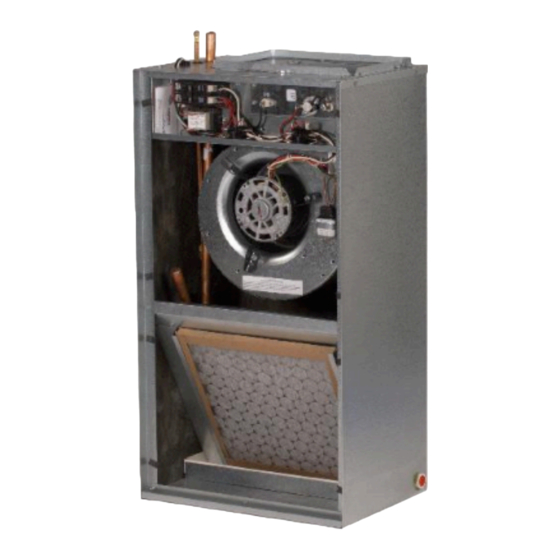
2. Introduction
The AEW Series air handlers are versatile upflow only models that
can be recess mounted or flush mounted onto walls. These air han-
dlers have the following standard features:
I. Application Versatility
Front or bottom return air position. Offset hanging brackets attach to
unit and wall to allow hanging inside closet.
Can be ARI matched with most brands of air conditioners or heat
pumps for use with either R22 or R410a when proper metering de-
vice is used.
II. Motor
X13 speeds and torques are controlled by software embedded in the
motor to maintain constant torque. Motors are pre-programmed at
the factory.
III. Cabinet
Sturdy, short galvanized steel cabinet with painted front panels. Cab-
inet fully insulated with 1/2" faced insulation to prevent sweating and
mold growth, to encapsulate glass fibers, and to provide excellent
R-value. Stick pins ensure insulation remains in place.
Units ship with disposable filter in filter rack.
IV. Modular Electric Heat Kits
Heat kits available with either circuit breakers or terminal blocks.
Available in 3, 5, 8, & 10 KW. Models with electric heat include se-
quencers and temperature limit switches for safe, efficient operation.
Modules are easily installed in the field using molex plugs or can be
ordered factory-installed. Controls are accessible from the front for
easy service.
Electrical connections can be made from the top or left. Disconnect
does not protrude through the wall panel.
Fan time delay relay standard for increased efficiency.
V. Blower
Direct drive multi-speed blowers circulate air quietly and efficiently.
Motor speeds can be easily selected via motor terminals. Swing
mounted blowers can be easily removed for service.
VI. Electronic Circuit Board
Electronic circuit board provides 30 sec. ON/OFF blower time delay
extracting more heat/cool from the coil
1
Advertisement
Table of Contents

Related Manuals for Aspen AEW18


Summary of Contents for Aspen AEW18
- Page 1 WARNING 208/240 V, single phase, 60 Hz power VI. Electronic Circuit Board supply. Aspen will not be responsible for Electronic circuit board provides 30 sec. ON/OFF blower time delay damages caused due to modification of the unit to operate extracting more heat/cool from the coil with alternative power sources.
-
Page 2: Warranty
Manufacturer will not accept dam- primary and secondary drain plug up and overflow. As expressed age claims for incorrectly shipped product. in our product warranty; ASPEN WILL NOT BE BILLED FOR ANY STRUCTURAL DAMAGES CAUSE BY FAILURE TO FOLLOW 4. Installation Preparation THIS INSTALLATION REQUIREMENT. - Page 3 (Fig 4E-2). In case of a front return application, the front access panel should be removed and discarded. Some Aspen coils may include a Schrader CAUTION valve on the suction manifold. Ensure that the Schrader valve and valve core (where present) are protected from heat during brazing and instal- lation to prevent leakage.
-
Page 4: Installation
I-3. Slide attachment the nut onto 8. Metering Devices/Liquid Line Connection the liquid line stub out. Aspen coils are available with two kinds of metering devices a) flow- rator or b) TXV. The following instructions are separated into sec- tions by metering device. -
Page 5: Piston Replacement
I-6. Tighten the nut to a torque of approximately 10-30 ft-lbs. Do NOT overtighten the nut. Overtightening will impede the piston movement during operation. II-6. Replace the piston with one of the correct size. Do not force II. Piston Replacement the new piston into the body. - Page 6 II. TXV Bulb Vertical Mounting The valves should be sized according to CAUTION the capacity of the outdoor unit. Failure to install the right valve can lead to poor per- formance and possible compressor damage. As recommended in Section 8B-I, the TXV sensing bulb should be mounted in a hori- I.
- Page 7 III-10. Tighten all connections taking care to use proper back up. III-11. Remove the valve identification sticker from the valve and place it adjacent to the Aspen model number on unit name plate. III-12a. Some Aspen coils come with a Schrader valve on the suc- tion line.
-
Page 8: Connecting Refrigerant Lines
9. Connecting Refrigerant Lines 7. Flow nitrogen through the piping when brazing. 8. Braze both refrigerant line connections using proper brazing pro- cedures. Release nitrogen hold- 9. When all line connections are brazed, perform a proper system ing charge by depressing the evacuation procedure per the outdoor unit manufacturer instructions. -
Page 9: Low Voltage Connections
Line voltage wiring should be routed through the access holes at the top of the air handler. Proper electrical conduit con- nection fittings should be used. Connect the power wiring to the line side connections on the air handler. The electrical ground wire should be connected to the grounding lug. -
Page 10: Condensate Drain
5. If outdoor unit instructions and charts are not available, use Aspen provided charts. Make certain indoor air temperature is near comfort level setpoint 75F, prior to establishing superheat and subcooling levels. - Page 11 15B . Expansion Valve Coils Add refrigerant until the subcooling measured at the outdoor unit liquid line matches the subcooling recommendation of the outdoor manufacturer (typically 7º – 10º F). If chart is unavailable refer to Table 15B-1. Table 15B-1. 16.
- Page 12 18. Wiring diagram for AEW models Fig 18-1. IO-123106 Effective 07/15/2015...
- Page 13 19. Wiring diagram for AAW models Fig 19-1. IO-123106 Effective 07/15/2015...
- Page 14 373 Atascocita Rd. Humble, TX 77396 Phone: 281.441.6500 Toll Free: 800.423.9007 Fax: 281.441.6510 www.aspenmfg.com Revised 07/15/2015. Subject to change without notice and without incurring obligation. © Copyright 2014 Aspen Manufacturing. All Rights Reserved IO-123106 Effective 07/15/2015...
Need help?
Do you have a question about the AEW18 and is the answer not in the manual?
Questions and answers