
Related Manuals for Granville-Phillips 475 Series

Summary of Contents for Granville-Phillips 475 Series
- Page 1 Series 475 ® ® Granville-Phillips Series 475 Convectron Vacuum Measurement Controller Instruction Manual Instruction manual part number 475101 Revision G - January 2015...
- Page 3 ® Granville-Phillips Series 475 Convectron Vacuum Measurement Controller This Instruction Manual is for use with all Granville-Phillips Series 475 Vacuum Measurement Controllers. A list of applicable catalog numbers is provided on the following page. This product is RoHS compliant. Customer Service/Support...
- Page 4 Granville-Phillips Series 475 Convectron Vacuum Measurement Controller Catalog numbers for Series 475 Convectron Vacuum Measurement Controller with Graphic Display 1/8 DIN Panel Mount or Benchtop Mount Controller: 475001 - X X - X 1/8 DIN Panel Mount or Benchtop Mount...
-
Page 5: Table Of Contents
Table of Contents Chapter 1 Safety & Introduction ........Caution and Warning Statements . - Page 6 Table of Contents Correction Factor Parameters ......Error Codes ........Preparing For Convectron Gauge Operation .
- Page 7 Table of Contents Command Descriptions ......Command-Response Timing ......RS-485 Troubleshooting .
- Page 8 Table of Contents Series 475 Convectron Gauge Controller Instruction Manual 475101 - Rev. G...
-
Page 9: Chapter 1 Safety & Introduction
Controller. Failure to comply with the instructions violates standards of design, manufacture, and intended use of the Controller. Granville-Phillips and Brooks Automation disclaim all liability for the customer's failure to comply with the instructions. • Read instructions – Read all instructions before installing or operating the Controller. -
Page 10: System Grounding
Chapter 1 WARNING Read these safety notices and warnings before installing, using, or servicing this equipment. If you have any doubts regarding the safe use of this equipment, contact the Granville−Phillips Customer Service department at the address listed in this user manual. -
Page 11: Operation
Extended Warranty MKS Instruments, Inc. provides an extended warranty period to five (5) years from the date of shipment for the Granville-Phillips Series 475 Controllers. The MKS Instruments, Inc. General Terms and Conditions of Sale provides the complete and exclusive warranty for Granville-Phillips products. This document is located on our web site at www.mksinst.com, or may be... -
Page 12: Damage Requiring Service
Chapter 1 When returning a products to Granville-Phillips, be sure to package the products to prevent shipping damage. Circuit boards and modules separated from the gauge assembly must be handled using proper anti-static protection methods and must be packaged in anti-static packaging. Granville-Phillips will supply return packaging materials at no charge upon request. -
Page 13: Specifications & Compliance
Safety & Introduction 1.12 Specifications & Compliance Table 1-1 Specifications & Compliance for the Series 475 Controller and 275 Convectron Gauge Parameter Specification See notes 1 and 2, below Measurement Range for N / Air Torr 1x10 to 999 Torr mbar 1x10 to 1333 mbar... - Page 14 Chapter 1 Table 1-1 Specifications & Compliance for the Series 475 Controller and 275 Convectron Gauge Parameter Specification Other materials exposed to gas 304 stainless steel, borosilicate glass, Kovar, alumina, NiFe alloy, polymide Internal volume 40 cm (2.5 in. Weight 85 gm (3 oz.) Mounting orientation Horizontal preferred...
-
Page 15: Chapter 2 Installation
Chapter 2 Installation System Components Figure 2-1 and Figure 2-2 illustrate all available options and system capabilities, including Controllers with process control and RS-232 or RS-485 computer interface options. Figure 2-1 Series 475 Convectron Controller Front and Rear Panels Figure 2-2 Convectron Vacuum Measurement System Components 2-channel process control connector... - Page 16 Chapter 2 Table 2-1 475 Controller Factory Defaults Setting Range or Selection Factory Default Setting Units of Measure Torr, mbar, pascal Torr, mbar, or pascal as selected when the Controller was purchased. Gas Species , Ar, O , He, CO FS, CF Correction Factor 0.1 to 1.5...
-
Page 17: Pre-Installation Considerations
Installation Table 2-1 475 Controller Factory Defaults Setting Range or Selection Factory Default Setting • Hardware RTS / CTS or None None Handshake RS-485 • Baud Rate Baud Rate: 1200, 2400, 19200 baud 4800, 9600, 14400, 19200, 28800, 38400 • Data Format Bits: 8 data bits, No parity, 1 •... -
Page 18: Installation Procedure
Before you install the Controller, install appropriate pressure relief devices in Devices the vacuum system. Granville-Phillips does not supply pressure relief valves or rupture disks. Suppliers of pressure relief valves and pressure relief disks can be located via an on-line search, and are listed on ThomasNet.com under “Relief Valves”... - Page 19 Installation Figure 2-3 Controller Dimensions The Controller may be free-standing or panel-mounted. For free standing (benchtop) use, install the provided self-adhesive rubber feet on the bottom of the Controller. To use the Controller in a free-standing (benchtop) configuration: 1. Apply the four provided adhesive rubber mount feet on the bottom of the Controller.
-
Page 20: Install The Convectron Gauge
Chapter 2 the bullet points listed above. 2. Remove the Front Panel (bezel) as shown in Figure 2-5. Hold the Controller in your hands and use your thumbs to push on the bezel. Push the bottom of the bezel loose, then the top. Figure 2-5 Remove the Front Panel (bezel) 3. -
Page 21: Install Vacuum Chamber Fittings
Installation Figure 2-7 Convectron Gauge Installation • Do not locate the Convectron Gauge near the pump, where gauge pressure might be lower than normal vacuum pressure. • Do not locate the gauge near a gas inlet or other source of contamination, where inflow of gas or particulates causes atmospheric pressure to be higher than system atmosphere. -
Page 22: Ground The Convectron Gauge
Chapter 2 VCR Type Fitting 1. Remove the plastic or metal bead protector cap from the fitting. 2. If a gasket is used, place the gasket into the female nut. 3. Assemble the components and tighten them to finger–tight. 4. While holding a back-up wrench stationary, tighten the female nut 1/8 turn past finger-tight on 316 stainless steel or nickel gaskets, or 1/4 turn past finger-tight on copper or aluminum gaskets. -
Page 23: Connect The Wiring
Installation Figure 2-8 Convectron Gauge to Vacuum Chamber Ground Connection The 475 Controller has connectors for Convectron Gauge cable, RS-232, Connect the Wiring RS-485/422, setpoints, analog output cable, and power supply wiring, as illustrated in Figure 2-9 ( shown with the optional RS-232 and setpoint connectors Figure 2-9 Convectron Gauge, Output, and Power Connections Chassis... - Page 24 2. User supplied power to the Controller using a wire adapter and plug to connect to a 12 to 24 Vdc supply voltage (Granville-Phillips part number 167820). If you use the wire adapter, the wires to be connected to the...
-
Page 25: Connectors
Installation Connectors The following figures illustrate the connectors on the back of the 475 Controller. Figure 2-11 I/O (RS-485/RS-422) 9-Pin Connector (pins) Figure 2-12 I/O (RS-232) 9-Pin Connector (pins) Figure 2-13 Convectron Gauge 9-Pin Connector (sockets) Figure 2-14 2-Channel Process Control Connector (pins) Figure 2-15 Analog Output Connector (socket) Convectron Gauge Analog... -
Page 26: Configure The Relays For The Application
Chapter 2 Figure 2-16 3-Pin Power Supply Connector Configure the Relays • To configure the setpoint relays for the process control option, see for the Application page 57. • To configure the setpoint relays using the RS-232 option, see PCE Relays on page 69. -
Page 27: Chapter 3 Operation
Chapter 3 Operation Preparing for Before you prepare for process measurement, make sure: Pressure • The Controller was properly set up and installed per the instructions in Measurement Chapter 2. • The gas in your vacuum system is air or N . -
Page 28: Menu Overview
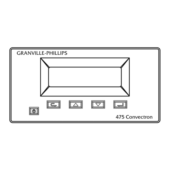
Chapter 3 Figure 3-2 Series 475 Convectron Gauge Controller System Menu Flowchart Menu Overview All functions, settings, and options can be accessed and displayed by using the four buttons on the front panel of the Controller. Some of the displayed settings are for information only, and others can be changed and saved. -
Page 29: Product Information
Operation 3.4.1 Product Product information allows the user to read the product revision and Information installed options. 1. Press the UP or DOWN button to scroll to “Product Info” and press the ENTER button. 2. Press the UP or DOWN button to browse the product information. 3. -
Page 30: 3.4.4 Calibrate
Chapter 3 ENTER button. 2. Press the UP or DOWN button to select “Auto Test”, “Meas. Circuit”, or “Analog Output” and press the ENTER button. • Auto Test All Performs the “Auto Test” described above. 1. Press the ENTER button to allow the 475 Controller to automatically perform a self diagnostics test. -
Page 31: Configure
Operation pressure display. • Calibrate Vacuum 1. Press the UP or DOWN button to select the desired calibration setting and press the ENTER button. 2. Press the BACK button a few times or wait one minute to return to pressure display. Configure The Configure menu item allows the user to view, select, and set the control functions of the 475 Controller. -
Page 32: Parameters
Chapter 3 3.5.2 RS-232 The RS-232 interface permits data output to, and operational control by, a Parameters host computer. Output control is either by a command response mechanism – or a hardwire control line between RTS and CTS. A variety of baud rates and byte framing options are available. -
Page 33: 3.5.4 Analog Output
Operation 3. Press the BACK button a few times or wait one minute to return to pressure display. Data Format 1. The indicated setting will show in reverse video. Use the UP and DOWN buttons to scroll to the desired Data Format setting. 2. -
Page 34: 3.5.5 Pressure Units
Chapter 3 pressure display. Analog Offset 1. The indicated setting will show in reverse video. Press the UP or DOWN button to select the desired Analog voltage offset. 2. Press the ENTER button to save the selection. 3. Press the BACK button a few times or wait one minute to return to pressure display. -
Page 35: 3.5.7 Gas Species
Operation 2. Press the UP or DOWN button to select “Display Options” and press the ENTER button. 3. Press the UP or DOWN button to select “Show Setpoints” and press the ENTER button. 4. Press the UP or DOWN button to change the setpoint display status to “Yes”... -
Page 36: Pressure Filtering
Chapter 3 using the Menu buttons on the front of the Controller. See Correction Factor Parameters on page 38. At the time the gas species is changed, a pressure high-limit is changed so that a warning is given of possible over-pressure conditions. If a correction factor is entered, you can enter an upper limit. -
Page 37: Restore Configuration
Operation 3.5.9 Restore “Restore Configuration” allows the user to switch to any of the four saved Configuration configurations. Four different configurations (one factory default and three user-set configurations) can be programmed and saved. Each user setting will include unique setpoint parameters, unit of measure, analog output setting, computer interface parameters, atmosphere and vacuum calibrations, gas species setting, and display options. -
Page 38: Correction Factor Parameters
Chapter 3 3.5.12 Correction The Correction Factor is a scaling of a pressure reading to a new reading. The Factor Parameters Correction Factor (CF) can be applied when a gas other than N is a constant multiplication factor (rather than a curve) of N . -
Page 39: Error Codes
Operation Error Codes A known error produces an error code that is displayed to the user. More than one error results in a rotation of errors on the display. An error is also reported to the user through digital communications. When there are errors, the pressure readout is readjusted to a smaller font. -
Page 40: Preparing For Convectron Gauge Operation
Chapter 3 Preparing For Convectron Gauge pressure is indicated on the Controller front panel Convectron Gauge display. Operation Install pressure limiting devices calibrated to a level that the vacuum system can safely withstand. In addition, install pressure relief valves or rupture disks that will release pressure at a level considerably below the maximum safe pressure level of the system. -
Page 41: Convectron Gauge Sensors
The factory specified function can be used when the factory, at the request of the customer, has loaded a bridge voltage vs. pressure relationship that is specific to the Controller - cable - gauge combination. Contact Granville-Phillips for more details. Series 475 Convectron Gauge Controller Instruction Manual 475101 - Rev. G... - Page 42 Chapter 3 3.10.2 Indicated vs. NOTE: Use the information in this section only if you are NOT using True Pressure for the Calibrated Gas Species function of the 475 Controller. The 475 Gases Other Than N Controller uses lookup tables of bridge voltages and pressures to or Air convert the voltage given from the Analog-to-Digital converter (A/D) to a pressure reading.
-
Page 43: 3.10.3 Examples
Operation You must ensure that the atmosphere adjustments for the Convectron Gauge are correctly set. (See Atmosphere Calibration on page 51.) Figure 3-5 through Figure 3-10 show the true pressure vs. indicated pressure for 11 commonly used gases. Table 3-2 will help to locate the proper graph. Table 3-2 Pressure vs. - Page 44 Example 3: True to indicated pressure conversion Assume you want to set a process control setpoint at a true pressure of 20 Torr of CO . On Figure 3-6, locate 20 Torr on the true pressure scale, travel horizontally to the right to the CO curve, then down to an indicated pressure of 6.4 Torr (N equivalent).
- Page 45 Operation –4 –1 Figure 3-5 Convectron Gauge Indicated vs. True Pressure Curve; 10 to 10 Torr Series 475 Convectron Gauge Controller Instruction Manual 475101 - Rev. G...
- Page 46 Chapter 3 Figure 3-6 Convectron Gauge Indicated vs. True Pressure Curve; .01 to 1000 Torr Series 475 Convectron Gauge Controller Instruction Manual 475101 - Rev. G...
- Page 47 Operation Figure 3-7 Convectron Gauge Indicated vs. True Pressure Curve; .01 to 1000 Torr Series 475 Convectron Gauge Controller Instruction Manual 475101 - Rev. G...
- Page 48 Chapter 3 –4 –1 Figure 3-8 Convectron Gauge Indicated vs. True Pressure Curve; 10 to 10 mbar Series 475 Convectron Gauge Controller Instruction Manual 475101 - Rev. G...
- Page 49 Operation Figure 3-9 Convectron Gauge Indicated vs. True Pressure Curve; .01 to 1000 mbar Series 475 Convectron Gauge Controller Instruction Manual 475101 - Rev. G...
- Page 50 Chapter 3 Figure 3-10 Convectron Gauge Indicated vs. True Pressure Curve; .01 to 1000 mbar Series 475 Convectron Gauge Controller Instruction Manual 475101 - Rev. G...
-
Page 51: Calibration
Operation 3.11 Calibration Each Convectron Gauge is individually calibrated for N . “Zero” adjustment of the gauge should not be necessary unless readout accuracy is required –3 below 1 x 10 Torr or the gauge has been contaminated. Adjustment of the atmospheric indication should not be necessary unless compensating for long cables, variations in mounting orientation, or contamination. -
Page 52: Torr
Chapter 3 To reset VAC and ATM back to their original factory settings, turn OFF the Controller and hold the ENTER button while turning ON power to the Controller. “Factory CAL” is displayed for approximately three seconds. The Controller will then resume normal power on operation. -
Page 53: Convectron Gauge Analog Output Signal
Operation 3.12 Convectron Gauge A voltage output signal proportional to the common logarithm of the Analog Output Signal pressure indication is provided on the rear panel of the Controller via a standard 1/8 inch miniature phone jack. If graphed on loglinear axes, the output voltage is linear in proportion to the log of pressure (see Figure 3-11). - Page 54 Chapter 3 Figure 3-11 Convectron Gauge Analog Output vs. Pressure Series 475 Convectron Gauge Controller Instruction Manual 475101 - Rev. G...
-
Page 55: Default Analog Output Of 0 To 7 V
Operation 3.12.1 Default Analog The output equations for 0 to 7 V are: Output of 0 to 7 V P = 10 Torr (P = Pressure) (V = Analog Output Voltage) P = 10 mbar P = 10 3.12.2 Optional In some applications a 0 V output is used to indicate that the Controller is Analog Output of OFF. -
Page 56: Analog Output Mode Programming
Chapter 3 Table 3-4 Converting Measured Voltage to Pressure Segment # Coefficients Voltage Range = -7.184400E+03 6.54785 to 7.3828 = +7.117083E+00 = -2.354167E-03 = +2.604167E-07 = -5.439800E+04 7.3828 to 7.6465 = +4.990375E+01 = -1.528125E-02 = +1.562500E-06 = +1.811462E+06 7.6465 to 7.9102 = -1.511014E+03 = +4.196562E-01 = -3.880208E-05... -
Page 57: Chapter 4 Process Control
Relay Configuration: Normally Closed, Normally Open, Common (NC, NO, C). Relay Contact Rating: 5 A, 250 VAC, or 30 Vdc, resistive load. 7. If you desire application assistance, contact a Granville-Phillips application engineer. See Customer Service on page 99 for contact information. -
Page 58: Connecting Process Control Relays
Control Relays is marked with letters identifying each pin. See Connectors on page 25. A mating connector (Granville-Phillips part number 0167820) is supplied in the hardware kit. 1. Using a drawing of the process control output connector and the circuit schematics you have prepared, make a cable to connect the various system components to be controlled. -
Page 59: Process Control Tips
Process Control Polarity 1. The indicated setpoint polarity setting will show in reverse video. Press the UP or DOWN button to select “Normal” or “Reverse”. 2. Press the ENTER button to save the selection. 3. Press the BACK button a few times or wait one minute to return to pressure display. -
Page 60: Process Control Relay Trip Points
Chapter 4 Process Control Relay The 475 Controller is shipped from the factory with the trip point relays set Trip Points to a pressure of 1.00E-4 Torr. The relays need to be adjusted for your application. The trip point may be set from 1 x 10 –4 Torr to 999 Torr. -
Page 61: Interface
Chapter 5 RS-232 Interface RS-232 Theory of The RS-232 interface option permits data output to, and Convectron Gauge Operation for the 475 control by, a host computer. Output control is by a command response – Controller mechanism and a hardwire control line between RTS (Request To Send) and CTS (Clear To Send). -
Page 62: Rs-232 Handshake
Chapter 5 Table 5-1 RS-232 Connector Pin Assignments Signal Pin Number Direction Signal Ground – Transmitted Data (TXD) To Computer Received Data (RXD) To Controller Data Set Ready (DSR) To Computer Clear To Send (CTS) To Controller Request To Send (RTS) To Computer Not Used 1 and 4... - Page 63 RS-232 Interface Table 5-4 RTS/CTS Handshake Display Readouts Display Readout Byte Format “Handshake disabled” Disable RTS/CTS handshake “Handshake enabled” Enable RTS/CTS handshake When the handshake is enabled: 1. Upon receiving the terminator, the Controller will assert the RTS line as a holdoff to prevent the host computer from attempting to transmit further data until the message just received has been parsed and a reply has been sent.
-
Page 64: Command-Response Timing
Chapter 5 Command-Response The timing diagram illustrated in Figure 5-2 depicts the time it takes for a Timing command to be transmitted to the 475 Controller, processed, a response sent back. Figure 5-2 Command Response Timing Diagram - Duration of the transmission of the command from the Host to the 475 Controller. -
Page 65: Command Syntax
RS-232 Interface RS-232 Command A command from the host must include data and a terminator Syntax (data)(terminator). The terminator is an ASCII carriage return, the 0D character, denoted here by the ↵ symbol. The data field is explained in the command descriptions. All alpha characters can be upper or lower case. -
Page 66: Ao Set Analog Output Mode
Chapter 5 Analog Output Definition: Get/Set the analog output mode. Modifiers: 1, 2, or 3 Response: PROGM OK↵ Example: From host computer: AO1↵ (or AO2, or AO3) From 475 Controller: PROGM OK↵ • Command AO1 sets the analog output to log 0-7V. •... -
Page 67: Dt Perform Diagnostic Tests
RS-232 Interface Diagnostics Test Definition: Perform diagnostics tests on A/D and analog out. Modifiers: C, CS, CE, CP, CV, CD A, A#, AD Response: See the examples, below. Examples: Command Root From Host Computer From 475 Controller PASS↵ Run auto test on A/D and DT↵... -
Page 68: Gs Modify Gas Species Settings
Chapter 5 Gas Species Definition: Get/Set gas species commands. See Gas Species on page 35 for a detailed explanation. Modifiers: (Nitrogen), AR (Argon), HE (Helium), CO (Carbon Dioxide), O (Oxygen) FS (Factory Specified), CF (Correction Factor). Response: See the examples, below. Examples: Command Root... -
Page 69: Kp Enable/Disable Keypad
RS-232 Interface Keypad Definition: Get the keypad status, or Enable/Disable the keypad on the 475 Controller. Modifiers: 1 or 0 (1 = enable, 0 = disable). Response: PROGM OK↵ Examples: From host computer: KP↵ Get the Keypad status (Enabled or Disabled) From 475 Controller: 1↵... -
Page 70: Pch
Process Control Definition: Set the process control setpoint hysteresis. Setpoint Modifiers: 1, or 2 (for setpoint 1 or 2). Hysteresis Possible Responses: PROGM OK↵ RANGE ERR↵ The value entered is <5 or >1000. Examples: From computer: PCH1↵ Get setpoint 1 hysteresis. From 475 Controller: 200↵... -
Page 71: Rd Read The Pressure
RS-232 Interface Read Pressure Definition: Read Convectron Gauge pressure response. Modifiers: None. Possible Responses: Pressure value 9.34E-02↵ Defective transducer OPN SNSR↵ Sensor is unplugged SNSR UNP↵ Under pressure, limit related to TZ SNSR UDP↵ command Pressure higher than 999 Torr, or SNSR OVP↵... -
Page 72: Set The Baud Rate
Chapter 5 Set Baud Rate Definition: Set the baud rate Modifiers: 1200, 2400, 4800, 9600, 14400, 19200, 28800, 38400. Response: PROGM OK↵ Example: From host computer: SB19200↵ From 475 Controller: PROGM OK↵ The baud rate needs to be set at a valid rate, i.e., 1200, 2400, 4800, 9600, 19200, 38400. -
Page 73: Su Set The Units Of Pressure
RS-232 Interface Possible Responses: AU↵ (or PT↵ ) or PROGM OK↵ Examples: From host computer: ST↵ get currently selected sensor type From 475 Controller: AU↵ current sensor type is gold-plated tungsten From host computer: ST PT↵ change sensor type to Platinum From 475 Controller: PROGM OK↵... -
Page 74: Uc Restore/Save User Configuration
Chapter 5 RANGE ER↵ Command error. TZ must be set below 1 x 10 Torr, and system pressure must be – below 1 x 10 Torr. – INVALID↵ System is NIST calibrated and locked. Examples: From host computer: TZ0↵ From 475 Controller: PROGM OK↵ From host computer: TZ1.00E –... -
Page 75: Troubleshooting
RS-232 Interface From 475 Controller: 030409 C↵ – Because the RS 232 standard is found in various configurations, check the Troubleshooting following configuration options. 1. Check the RS-232 setting via the front panel of the 475 Controller. Be sure the baud rate, character format and framing, and interface protocol are matched to the requirements of your host computer or terminal. - Page 76 Chapter 5 Series 475 Convectron Gauge Controller Instruction Manual 475101 - Rev. G...
-
Page 77: Interface
Chapter 6 RS-485 Interface RS-485/422 Computer This option permits data output to, and operational control by, a host Interface Setup computer. Output control is by a command-response mechanism. If you have this module in your unit, configure it to your system requirements as directed in this chapter. -
Page 78: 6.3.3 Address
Chapter 6 • ""7O1" - 7 Data Bits, Odd Parity, 1 Stop Bit These formats can be selected through the "SPN", "SPE", "SPO" commands and the front panel (Configure > RS485 Parameters > Data Format). 6.3.3 Address The 475 uses an addressing system since more than one 475 can be on the same bus. - Page 79 RS-485 Interface 2. RS-485 2-wire (optional) Computer unit 1 unit 2 In this example, multiple 475 Controllers are transmitting and receiving over one pair of wires in a multi-point configuration. 3. RS-485 4-wire (default) Computer unit 1 unit 2 In this example, multiple 475 Controllers are transmitting over one pair of wires in a multi-point configuration and receiving over a second pair of wires in a multi-drop configuration.
-
Page 80: Connecting The Rs-485/422 Computer Interface
Chapter 6 6.4.1 Connecting the RS-485/422 Computer Interface Figure 6-1 475 Controller Rear Panel Showing RS-485/422 Connector RS-485 Connector. See Figure 2-11 on page 25. NOTE: The Service Port is for factory use only. This factory or field installed option produces the signals shown in Table 6-3. -
Page 81: Communications Protocol
RS-485 Interface Verify that the host computer's communication settings (baud rate, byte format, etc.) are the same as the 475 Controller. See Section 6.3 and Table 6-1. Communications The 475 Controller uses a command-response half-duplex protocol. If the Protocol 475 Controller recognizes received data as a valid command, it will check the command string address and compare with its own. -
Page 82: Command Descriptions
Chapter 6 6.7.1 Command Descriptions Table 6-5 List of RS-485 User Commands RST to Command Description Page Change Set analog output mode Get/Set analog output offset Get calibration status Perform diagnostic tests Set calibration to factory defaults Modify gas species settings Enable/Disable keypad Enable/Disable LPF (Low-Pass Filter) Get or set process control setpoint value... -
Page 83: Ao Set Analog Output Mode
RS-485 Interface NOTES: "#01" is appended to all "From host computer" examples. "*01" is appended to all "From 475 Controller" examples. All of the examples below assume an address of 0x01. See Section 6.9.1 for a list of common error messages. Analog Output Definition: Get/Set the analog output mode. -
Page 84: Dt Perform Diagnostic Tests
Chapter 6 Diagnostics Test Definition: Perform diagnostics tests on A/D and analog out. Modifiers: C, CS, CE, CP, CV, CD, A, A#, AD Responses: See the examples, below. Examples: Command Root From Host Computer From 475 Controller *01 PASS↵ Run auto test on A/D and #01 DT↵... -
Page 85: Gs Modify Gas Species Settings
RS-485 Interface Gas Species Definition: Get/Set gas species commands. See Gas Species on page 35 for a detailed explanation. Modifiers: (Nitrogen), AR (Argon), HE (Helium), CO (Carbon Dioxide), O (Oxygen) FS (Factory Specified), CF (Correction Factor). Responses: See the examples, below. Examples: Command Root... -
Page 86: Kp Enable/Disable Keypad
Keypad Definition: Get the keypad status, or Enable/Disable the keypad on the 475 Controller. Modifiers: 1 or 0 (1 = enable, 0 = disable). Possible Responses: *01 PROGM OK↵ Examples: From host computer: #01 KP↵ Get the Keypad status (Enabled or Disabled) From 475 Controller: *01 1↵... -
Page 87: Enable/Disable Relays
RS-485 Interface Relays Definition: Enable/Disable relays. Modifiers: 1 or 0 (1 = enable, 0 = disable). Possible Responses: *01 PROGM OK↵ Examples: Command Root From Host Computer From 475 Controller #01 PCE↵ Get relay status. *01 PROGM OK↵ #01 PCE01↵ Enable Relay 1, disable *01 PROGM OK↵... -
Page 88: Rd Read The Pressure
Chapter 6 Examples: Command Root From Host Computer From 475 Controller #01 PD↵ Get (show) the *01 150↵ current delay setting. #01 PD10↵ Set 10 ms *01 PROGM OK↵ delay. #01 PD150↵ Set 150 ms *01 PROGM OK↵ delay. Response Delay provides a delayed readout of the indicated pressure. The delay time can be set in 10 millisecond increments for the 475 Controller to display a pressure reading. -
Page 89: Ru Read Units Of Pressure
RS-485 Interface Read Pressure Definition: Identifies the currently selected units of pressure. Unit Modifiers: Torr, mbar, Pascal. Possible Responses: *01 TORR or *01 MBAR or *01 PASCAL Example: From host computer: #01 RU↵ From 475 Controller: *01 TORR See SU (Set Unit of Pressure) to change the displayed unit of measurement to another. -
Page 90: Get The Serial Number
Chapter 6 Serial Number Definition: Get the serial number of the 475 Controller. Modifiers: None. Response: *01 475A1234↵ Example: From host computer: #01 SN↵ From 475 Controller: *01 475A1234↵ The serial number can be up to 16 characters long. Set Parity to 7 Definition: Set bits/parity to 7 bits/even, 1 stop bit Bits/Even Parity... -
Page 91: Su Set The Units Of Pressure
RS-485 Interface Set Unit of Definition: Selects and sets the units of pressure measurement. Pressure Modifiers: T, M, or P (Torr, mbar, or pascal). Possible Responses: *01 PROGM OK↵ Example: From host computer: #01 SUT↵ From 475 Controller: *01 PROGM OK↵ SXVR Set Transceiver Definition: Sets the transceiver switching time from receiver... -
Page 92: Restore/Save User Configuration
Chapter 6 Sensor unplugged. No change ?01 SNSR UNP↵ in calibration. Command error. TZ must be ?01 RANGE ER↵ set below 1 x 10 Torr, and system pressure must be below 1 x 10 Torr. System is NIST calibrated and ?01 INVALID↵... -
Page 93: Command-Response Timing
RS-485 Interface Void NIST For NIST Traceable System Calibration: Calibration Definition: Void NIST calibration Modifiers: None Response: *01 PROGM OK↵ Calibration functions are now unlocked. TS, TZ, and FAC commands will now work. Read Version Definition: Read code version Modifiers: None Response: Code version number... -
Page 94: Troubleshooting
Chapter 6 RS-485 Because the RS-485 standard is found in various configurations, check the Troubleshooting following configuration options: 1. Check the RS-485 settings via the front panel of the 475 Controller. If there is no response, check the address of the Controller. Be sure the baud rate, bus type, transceiver mode, and parity match the requirements of the host computer or terminal. -
Page 95: Chapter 7 Diagnostics
Chapter 7 Diagnostics The 475 has diagnostic functions to help determine if critical areas are operating correctly. Some diagnostic functions are continuously running and some require user interaction. The Analog/Digital Converter (A/D) and the Analog Output are monitored continuously for errors. Figure 7-1 Diagnostics Flow Chart Figure 7-2... -
Page 96: Continuous Diagnostics
Chapter 7 Continuous The External A/D and the Analog Output are both monitored by the A/D Diagnostics onboard the microcontroller automatically. Discrepancies are reported to the user through the errors "ADBAD" and "AOBAD". Diagnostics Requiring User-interactive diagnostics can be accessed through the front panel, the User Interaction RS-232 interface, or the RS-485 interface. -
Page 97: Convectron Gauge Simulator
Diagnostics Convectron Gauge The 475 has an in-circuit Convectron Gauge Simulator that can be used for Simulator self-diagnostics or system setup. The simulator is controlled by a PWM-controlled voltage source similar to the Analog Output. It is calibrated in the same manner as the Analog Output. Changing the voltage of the simulator forces the Bridge Amplifier to change the voltage across a resistor network - effectively simulating a Series 275 gauge. -
Page 98: Analog Output Tests
Chapter 7 display and analog outputs can be set to a specific pressure, and the system process controller pressure input calibrated to match the pressure display of the 475 Controller. The voltage displayed during the simulation mode is the bridge voltage of the Convectron Gauge and not the analog output voltage from the 475 Controller. -
Page 99: Chapter 8 Service And Maintenance
Service Representative will advise you if the hazardous materials document is required. When returning a products to Granville-Phillips, be sure to package the products to prevent shipping damage. Circuit boards and modules separated from the gauge assembly must be handled using proper anti-static protection methods and must be packaged in anti-static packaging. -
Page 100: Damage Requiring Service
Chapter 8 Damage Requiring Turn OFF power to the Controller and refer servicing to qualified service Service personnel under the following conditions: • If any liquid has been spilled onto, or objects have fallen into, the Controller. • If a circuit board is faulty. •... -
Page 101: Error Codes And Possible Solutions
Service and Maintenance Error Codes and Table 8-1 lists failure symptoms and error codes, possible causes, and Possible Solutions possible solutions. NOTE: Running the Controller diagnostics can possibly assist you in determining if the problem is with the 475 Controller or the Convectron Gauge. - Page 102 Chapter 8 Table 8-1 Failure Symptoms or Error Codes, Possible Causes, and Possible Solutions Symptom or Error Code Possible Causes Possible Solutions ERR 15 ADBAD 1. The Analog/Digital Converter (A/D) is 1. Turn OFF, and turn ON power to the reporting an erroneous value.
-
Page 103: Convectron Gauge Test Procedure
Service and Maintenance Convectron Gauge The small diameter sensor wire can be damaged by even small voltages. Do Test Procedure not perform electrical continuity tests with instruments applying in excess of 0.1 V when the gauge is at vacuum, or 2 V when at atmospheric pressure. The Convectron gauge should show the resistances listed in Figure 8-1 (pin numbers are embossed on the gauge cable connector). -
Page 104: Reset To Factory Defaults
Chapter 8 Hold the gauge with the main body horizontal and the port projecting upward at an angle of 45 degrees. Slowly fill it with solvent using a standard wash bottle with the spout inserted in the port to the point where it touches the screen. -
Page 105: Index
Index Contact Information 3, 108 Analog Output From Convectron Gauge 53 Damage Requiring Service 12, 100 Scaling 56 Default Settings 104 Diagnostics 95 Before You Begin How to 29 Caution and Warning Statements 9 Display Damage Requiring Service 12 Setpoints 58 Reading and Following Instructions 9 Button Overview 27 Error Codes... - Page 106 Index Interface Settings 77 Overpressure Conditions 10 Physical Configurations 78 Overview Response Syntax 81 buttons 27 Troubleshooting 94 Power Up Service Initial 27 Guidelines 11 Preparing for Operation Service and Maintenance Analog Output Scale 56 Convectron Gauge Test Procedure 103 Button Overview 27 Customer Service 99 Calibration 51...
- Page 108 For Customer Service or Technical Support 24 hours per day, 7 days per week, every day of the year including holidays: Phone: +1-800-227-8766 or +1-303-652-4691 MKS, Granville-Phillips Division 6450 Dry Creek Parkway Longmont, CO 80503 USA Phone: 1-303-652-4691 or 1-800-776-6543...
Need help?
Do you have a question about the 475 Series and is the answer not in the manual?
Questions and answers