Table of Contents
Advertisement
Quick Links
Download this manual
See also:
Operating Manual
Advertisement
Table of Contents

Related Manuals for Interroll RollerDrive EC310


Summary of Contents for Interroll RollerDrive EC310
- Page 1 User manual Interroll RollerDrive EC310 Chapter-ID: User manual Chapter-ID: Version Chapter-ID: Translation of the original instructions Version 2.1 (08/2013) en Translation of the original instructions...
- Page 2 Fax. +49 2190 2022 www.interroll.com Copyright The copyright of this manual remains with Interroll Engineering GmbH. The operating instructions contain technical regulations and drawings which may not be reproduced partially or in full, transmitted by any means, utilized without permission for competitive purposes or disclosed to third parties.
-
Page 3: Table Of Contents
Technical specifications ........10 Performance Data for RollerDrive EC310 ......10 DriveControls for the RollerDrive EC310 . -
Page 4: Information About The Operating Instructions
Pass the manual on to any subsequent operator or occupant of the RollerDrive EC310. Interroll does not accept any liability for malfunctions or defects due to non- observance of this manual. If you have any questions after reading the operation manual, feel free to contact our customer service. -
Page 5: Further Symbols
RollerDrive EC310 Introduction Further symbols This symbol identifies possible material damage. Information about how to avoid damage. Important This symbol displays safety instructions. Hint This symbol marks useful and important information. This symbol marks the steps that have to be carried out. -
Page 6: Safety
RollerDrive EC310 Safety General safety instructions The RollerDrive EC310 is designed according to the technical state of the art and is reliable in operation, once distributed. However, risks may still arise. • Risks of physical injury to the user or bystanders. -
Page 7: Qualified Persons
Dangers Important The following list provides information about the various types of danger or damage that may occur while working with the RollerDrive EC310. Bodily injury Maintenance or repair work must only be performed by authorized and qualified persons in accordance with the applicable regulations. -
Page 8: Interfaces
RollerDrive EC310 Safety Interfaces By assembling the RollerDrive in a conveyor module, potential hazards may occur. These are not described in this manual and have to be analyzed during the design, installation, and startup of the conveyor module. After assembling the RollerDrive in a conveyor module, check the whole system for any new potential dangerous condition prior to turning on the conveyor. -
Page 9: Product Information
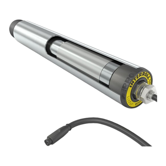
RollerDrive EC310 Product information Components RollerDrive EC310 Motor plug with cable Idler bearing housing assembly Motor shaft Tube Fixed bearing housing assembly Pipe coupling Motor Gears Fastening screw for idler shaft Version 2.1 (08/2013) en Translation of the original instructions... -
Page 10: Product Description
Holding brake The RollerDrive EC310 is fitted with an electronic holding brake that allows it to (Zero Motion Hold) be used on conveyors on a gradient or incline. The motor's rotor is held in position if no travel signal is pending. -
Page 11: Rollerdrive Label
RollerDrive EC310 Product information RollerDrive Label The information on the RollerDrive label is used to identify the RollerDrive. This is necessary in order to use the RollerDrive as intended. 03/10 16:1 37 W 24 VDC 0,05 – 0,98 m/s EC 310... -
Page 12: Technical Specifications
Hint Data applies to an ambient temperature of 20 °C (68 °F). Value can vary according to installation conditions, profile shapes and the resonance behavior of the system. Performance Data for RollerDrive EC310 Gear ratio Speed range Nominal torque Starting torque Holding torque 0.09 to1.75... -
Page 13: Drivecontrols For The Rollerdrive Ec310
Speed settings If you do not use the recommended DriveControl (see "DriveControls for the RollerDrive EC310", page 11), you may change the speed of the RollerDrive EC310 by altering the voltage on pin 5 of the motor plug. Speed setting on the... - Page 14 RollerDrive EC310 Product information External speed setting via digital inputs Speed input on the DriveControl * Speed at gear ratio 12:1 16:1 20:1 24:1 36:1 48:1 64:1 96:1 1.75 1.31 0.98 0.78 0.65 0.44 0.33 0.25 0.16 1.47 1.10 0.83 0.66...
-
Page 15: Motor Plug
(also see "Speed settings", page 11) Hint In case the RollerDrive is not directly connected to the corresponding DriveControl or the Interroll extension cable, connect the motor plug using a Conec M8 snap-in coupling. Pins 1 and 3 are not protected against incorrect polarity connection. -
Page 16: Dimensions Of The Motor Shaft
RollerDrive EC310 Product information Dimensions of the Motor Shaft 13 mm (0.51 in) 11 mm (0.44 in) hex 480 mm (18.9 in) 5 mm (0.2 in) BF/EL Dimensions of idler cartridges 11 mm (0.44 in) hex, Female threaded M8 (FTM8) shaft pin... - Page 17 RollerDrive EC310 Product information 11 mm (0.44 in) hex, Female threaded M8 (FTM8) shaft pin spring-loaded shaft PolyVee head IP66 31 mm (1,22 in) 4 mm (0,16 in) ø43 mm (1,7 in) SW 13 mm (0,51 in) Toothed belt head Poly-Chain GT;...
-
Page 18: Arrangement Of Round Belt Grooves
RollerDrive EC310 Product information Arrangement of Round Belt Grooves IGM8 female thread shaft pin, for tube diameter 50 mm single bearing min. 22 mm (0.87 in) min. 30 mm (1.2 in) ø38.4 mm (1.51 in) ø38.1 mm (1.5 in) min. 31.75 mm (1.25 in) min. -
Page 19: Transport And Storage
In the event of damage, take photos of the damaged parts. Report any damage caused by transport immediately to the transport company and Interroll to retain the right to claim for compensation. Do not expose the RollerDrives to serious fluctuations in temperature as this could lead to condensation. -
Page 20: Assembly
RollerDrive EC310 Assembly Warning information for assembly CAUTION Rotating parts Risk of pinched fingers Do not insert fingers between the RollerDrive and the round belt, PolyVee belt or roller chain. Install a protection device (such as a guard plate) to prevent fingers from getting trapped in the round belt, PolyVee belt or roller chain. -
Page 21: Warning Notices Concerning The Electrical Installation
RollerDrive EC310 Assembly Warning notices concerning the electrical installation Risk of damage to the motor and/or RollerDrive cables Observe the following safety information. All electrical work should only be performed by qualified and authorized persons. Disconnect the power supply before installing, removing or rewiring the RollerDrive. -
Page 22: Installing The Rollerdrive
RollerDrive EC310 Assembly Installing the RollerDrive Remove any packaging and transport safety devices from the RollerDrive. Inserting the motor shaft Hint • When installing the RollerDrive, particularly in coated profiles, it must be ensured that the fastening nuts and any star washers or torque safety devices used establish electrical contact with the profile to enable ground contact. - Page 23 RollerDrive EC310 Assembly Inserting the idler shaft The type of axis dictates how the idler shaft is inserted in the conveyor frame. The spring-loaded shaft is simplest to install. Inserting the spring-loaded hexagonal shaft Push the spring-loaded shaft inwards and align the shaft with the hole in the conveyor frame.
-
Page 24: Mounting Tool
RollerDrive EC310 Assembly Securing the RollerDrive in There is a nut on the shaft next to the tube. This inner nut has been the conveyor frame preassembled and secured in the correct position. Hint Do not twist the inner nut. -
Page 25: Initial Startup And Operation
RollerDrive EC310 Initial startup and operation Commissioning Ensure that no objects are in contact with rotating or moving parts. Pre-commissioning checks Ensure that all bolts are tightened according to the specifications. Ensure that there are no additional areas of danger caused by interfaces to other components. -
Page 26: Maintenance And Cleaning
RollerDrive EC310 Maintenance and cleaning Warnings concerning maintenance and cleaning CAUTION Risk of injury due to improper handling or accidental motor starts Maintenance work and cleaning may only be executed by qualified and authorized persons. Only perform maintenance work after switching off the power. -
Page 27: Troubleshooting
Wrong voltage at speed setting pin Check the voltage of the speed setting (if the RollerDrive is not operated pins on the motor plug. with the recommended Interroll DriveControl) Abnormal noise coming from the Motor or gearbox is damaged Replace the RollerDrive. -
Page 28: Abandonment And Disposal
RollerDrive EC310 Abandonment and disposal Abandonment CAUTION Risk of injury due to improper handling Abandonment may only be executed by qualified and authorized persons. Only abandon the RollerDrive after switching off the power. Ensure that the RollerDrive cannot be turned on accidentally. -
Page 29: Appendix
Part Part no. DriveControl 20 S-1001415 DriveControl 54 S-1001416 ZoneControl S-1004023 SegmentControl S-1004024 ComControl S-1004025 Connection accessories Part Properties Part no. Connecting cable Length: 2000 mm S-1004033 RollerDrive EC310 on DriveControl Version 2.1 (08/2013) en Translation of the original instructions... -
Page 30: Installation Declaration
The special technical documents as stated in Appendix VII B have been compiled and will be sent to the responsible authority if necessary. Person authorized to compile the technical documents: Georg Malina, Interroll Engineering GmbH, Hoeferhof 16, D - 42929 Wermelskirchen Applied EC directives: •... - Page 31 RollerDrive EC310 Appendix Version 2.1 (08/2013) en Translation of the original instructions...
- Page 32 Version 2.1 (08/2013) en For your local contacts please visit Translation of the original instructions interroll.com/contacts...
Need help?
Do you have a question about the RollerDrive EC310 and is the answer not in the manual?
Questions and answers