
Related Manuals for Interroll RollerDrive BT100


Summary of Contents for Interroll RollerDrive BT100
- Page 1 User manual Interroll RollerDrive BT100 Chapter-ID: User manual Chapter-ID: Version Chapter-ID: Translation of the original instructions Version 3.0 (04/2013) en Translation of the original instructions...
- Page 2 Fax. +49 2190 2022 www.interroll.com Copyright The copyright of this manual remains with Interroll Engineering GmbH. The operating instructions contain technical regulations and drawings which may not be reproduced partially or in full, transmitted by any means, utilized without permission for competitive purposes or disclosed to third parties.
-
Page 3: Table Of Contents
Motor cable and plug ........10 DriveControl for the RollerDrive BT100 ......10 Dimensions of the motor shaft . -
Page 4: Information About The Operating Instructions
Pass the manual on to any subsequent operator or occupant of the RollerDrive BT100. Interroll does not accept any liability for malfunctions or defects due to non- observance of this manual. If you have any questions after reading the operation manual, feel free to contact our customer service. -
Page 5: Further Symbols
RollerDrive BT100 Introduction Structure of warnings DANGER Nature and source of the hazard Possible consequence of non-observance Information about how to avoid the hazard. Further symbols This symbol identifies possible material damage. Information about how to avoid damage. -
Page 6: Safety
RollerDrive BT100 Safety General safety instructions The RollerDrive BT100 is designed according to the technical state of the art and is reliable in operation, once distributed. However, risks may still arise. • Risks of physical injury to the user or bystanders. -
Page 7: Qualified Persons
Dangers Important The following list informs you about the various types of danger or damage that may occur while working with the RollerDrive BT100. Persons Maintenance or repair work must only be executed by authorized and qualified persons in accordance with the applicable regulations. -
Page 8: Interfaces
RollerDrive BT100 Safety Interfaces By assembling the RollerDrive in a conveyor module, potential hazards may occur. These are not described in this manual and have to be analyzed during the design, installation, and startup of the conveyor module. After assembling the RollerDrive in a conveyor module, check the whole system for any new potential dangerous condition prior to turning on the conveyor. -
Page 9: Product Information
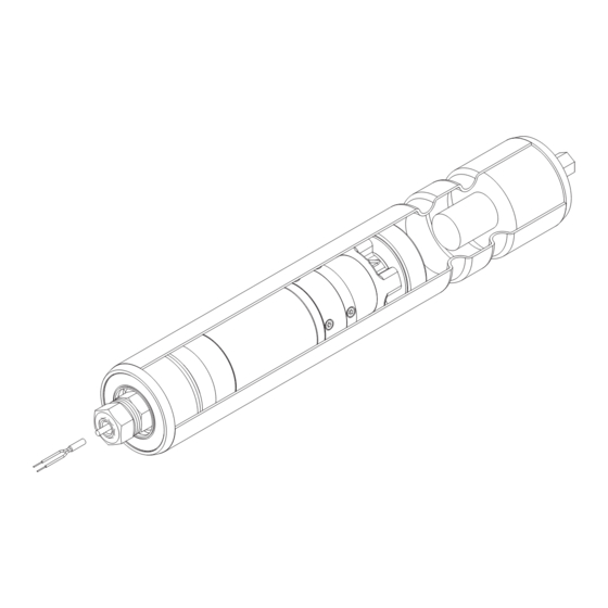
The RollerDrive BT100 is an electrically driven roller. It replaces external components such as motors and gears, which require frequent maintenance. The RollerDrive BT100 can be used in dusty and/or moist environments due to its protection class IP54. The RollerDrive BT100 is powered by a brushed, mechanically commutated 24 VDC motor. -
Page 10: Rollerdrive Label
RollerDrive BT100 Product information RollerDrive label The specifications on the RollerDrive label are used to identify the RollerDrive. This is required to use the RollerDrive as intended. 03/10 24:1 18 W 24 VDC 0,04 – 0,69 m/s EC 100 123456789... -
Page 11: Technical Specifications
RollerDrive BT100 Product information Technical specifications RollerDrive BT100 Rated voltage 24 VDC Voltage range 16 to 28 VDC Idle current 0.6 A Maximum continuous current 1.3 A Maximum peak current 4.5 A Mechanical power 11 W System efficiency (drive) Maximum ripple from power supply... -
Page 12: Performance Data
Motor cable Color Lead White 24 VDC Brown Ground Motor plug with grommet The motor plug for the RollerDrive BT100 is "CST-100-2 + Contact", manufactured by AMP. This version is dedicated to easy Z-Card connection. Color Lead 24 VDC Black Ground... -
Page 13: Dimensions Of The Motor Shaft
RollerDrive BT100 Product information Dimensions of the motor shaft Standard configuration Hex shaft AF 11 mm (0.44 in) 19.5 mm (0.77 in) 13.5 mm (0.53 in) 5000 mm (197 in) M12 x 1.5 mm 6 mm (0.24 in) Standard configuration for Z- Card connection Hex shaft AF 11 mm (0.44 in) -
Page 14: Dimensions Of Bearing Seats On The Non-Driven Side
RollerDrive BT100 Product information Dimensions of bearing seats on the non-driven side 11 mm (0.44 in) hex, Female threaded M8 (FTM8), Spring-loaded shaft Straight 5 mm (0.2 in) 15.5 mm (0.61 in) 5 mm (0.2 in) AF 13 mm (0.51 in) Round belt head 31 mm (1.22 in) -
Page 15: Round Belt Groove Locations
RollerDrive BT100 Product information Round belt groove locations Female thread IGM8, single for tube diameter 50 mm bearing min. 30 mm (1.2 in) min. 30 mm (1.2 in) ø38.5 mm (1.52 in) ø38.1 mm (1.5 in) min. 31.75 mm (1.25 in) min. -
Page 16: Transport And Storage
In case of damage, take photos of the damaged parts. To maintain the warranty, instantly report any damage caused during transport to the transport company and to Interroll. Do not transfer the RollerDrives between warm and cold environments as this may cause condensing water. -
Page 17: Assembly
RollerDrive BT100 Assembly Warning information for assembly CAUTION Rotating parts Risk of pinched fingers Do not insert fingers between the RollerDrive and the round belt, PolyVee belt or roller chain. Install a protection device (such as a guard plate) to prevent fingers from getting trapped in the round belt, PolyVee belt or roller chain. -
Page 18: Warning Notices For The Electrical Installation
RollerDrive BT100 Assembly Warning notices for the electrical installation Risk of damage to the motor and/or the wires of the RollerDrive Observe the following notices. The electrical installation may only be executed by qualified and authorized persons. Disconnect the power before installing, removing or rewiring the RollerDrive. -
Page 19: Rollerdrive Installation
RollerDrive BT100 Assembly RollerDrive Installation Remove the shipping tube from the RollerDrive. Inserting the motor shaft Hint Use caution when cutting the tie-wrap from the harness. Do not cut the sleeves or cables on the unit. Place the first star washer on the motor shaft. - Page 20 RollerDrive BT100 Assembly Inserting the idler shaft The type of axis dictates how the idler shaft is inserted in the conveyor frame. The spring-loaded shaft is simplest to install. Inserting the spring-loaded hexagonal shaft Push the spring-loaded shaft inwards and align the shaft with the hole in the conveyor frame.
-
Page 21: Mounting Tool
RollerDrive BT100 Assembly Securing the RollerDrive in There is a nut and a retaining washer on the shaft next to the tube. This inner nut the conveyor frame has been preassembled and secured in the correct position. Hint Do not adjust the inner nut and retaining washer. -
Page 22: Electrical Installation
RollerDrive BT100 Assembly Electrical installation The electrical installation depends on the version of the RollerDrive BT100: • With plug • With cable Connecting with plug Connect the motor plug to the DriveControl. Hint For the recommended DriveControls, see "DriveControl for the RollerDrive BT100", page 10. -
Page 23: Initial Startup And Operation
RollerDrive BT100 Initial startup and operation Initial startup Ensure that no objects are in contact with rotating or moving parts. Inspections before initial startup Ensure that all bolts are tightened according to the specifications. Ensure that no additional dangerous areas arise due to interfaces with other components. -
Page 24: Maintenance And Cleaning
RollerDrive BT100 Maintenance and cleaning Warnings concerning maintenance and cleaning CAUTION Risk of injury due to improper handling or accidental motor starts Maintenance work and cleaning may only be executed by qualified and authorized persons. Only perform maintenance work after switching off the power. -
Page 25: Troubleshooting
RollerDrive BT100 Troubleshooting Troubleshooting CAUTION Risk of injuries due to incorrect handling Troubleshooting may only be done by qualified and authorized persons. Only perform troubleshooting after switching off the power. Ensure that the RollerDrive cannot be turned on accidentally. -
Page 26: Abandonment And Disposal
RollerDrive BT100 Abandonment and disposal Abandonment CAUTION Risk of injury due to improper handling Abandonment may only be executed by qualified and authorized persons. Only abandon the RollerDrive after switching off the power. Ensure that the RollerDrive cannot be turned on accidentally. -
Page 27: Appendix
RollerDrive BT100 Appendix Accessories Belt Part Properties Round belt • Belts of 4 mm (0.16 in) and max. 5 mm (0.20 in) diameter PolyVee belt • Drive head with 9 grooves for flexible V-ribbed belts • PJ form, ISO 9981, DIN 7867 •... -
Page 28: Installation Declaration
The special technical documents as stated in Appendix VII B have been compiled and will be sent to the responsible authority if necessary. Person authorized to compile the technical documents: Georg Malina, Interroll Engineering GmbH, Hoeferhof 16, D - 42929 Wermelskirchen Applied EC directives: •... - Page 29 RollerDrive BT100 Appendix Version 3.0 (04/2013) en Translation of the original instructions...
- Page 30 Tel + 81 42 764 2677 Concord, Ontario L4K 2N2 Tel. + 49 2193 23 259 Poland jp.sales@interroll.com Canada be.sales@interroll.com Interroll Polska Sp. z o.o. Tel +1 905 660 4426 ul. Płochocińska 85 Korea ca.sales@interroll.com Czech Republic 03-044 Warszawa Interroll (Korea) Co. Ltd.
Need help?
Do you have a question about the RollerDrive BT100 and is the answer not in the manual?
Questions and answers